1
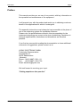
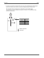
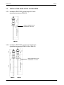
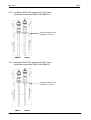
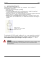
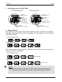
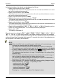
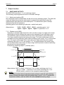
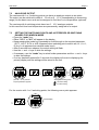
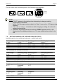
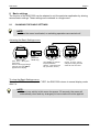
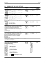
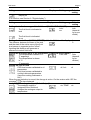
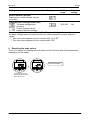
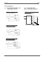
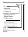
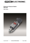
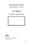
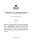
Electronic level switch
ENS 3000
User manual
(Translation of original instruction)
Status 09.11.2010
HYDAC ELECTRONIC GMBH
Part No. 669850
ENS 3000
Page2
Contents
34
1
Safety Information
5
2
Functions of the ENS 3000
5
3
Installation
5
GENERAL INSTALLATION NOTES
INSTALLATION USING HYDAC ACCESSORIES
Installation ENS 3000, probe length 250 mm
Installation ENS 3000, probe length 410 mm
Installation ENS 3000, probe length 520 mm
Installation ENS 3000, probe length 730 mm
IMPORTANT SAFETY NOTES
5
7
7
7
8
8
9
3.1
3.2
3.2.1
3.2.2
3.2.3
3.2.4
3.3
4
Starting up
10
5
Operating keys of the ENS 3000
11
6
Digital display
11
7
Output function
13
7.1
7.1.1
7.1.2
7.2
7.3
7.4
7.5
7.6
8
8.1
8.2
9
10
10.1
10.2
11
11.1
11.2
Status 09.11.2010
SWITCHING OUTPUTS
13
Switch point setting (SP)
13
Window mode (WIN)
13
ANALOGUE OUTPUT
14
SETTING THE SWITCHING POINTS AND
HYSTERESES OR SWITCHING RANGES FOR
WINDOW MODE
14
SETTING RANGES FOR THE SWITCHING OUTPUTS 15
SETTING RANGES FOR THE WINDOW FUNCTION 16
SETTING RANGES FOR THE OFFSET
16
Basic settings
17
CHANGING THE BASIC SETTINGS
SUMMARY OF THE BASIC SETTINGS
17
18
Resetting the peak values
21
Programming Enables
22
ALTERING THE OPERATING
PROGRAMMING ENABLE
CHANGING THE MAIN
PROGRAMMING ENABLE
23
Messages
24
ERROR MESSAGES
OTHER MESSAGES
24
25
HYDAC ELECTRONIC GMBH
22
Part No. 669850
ENS 3000
Page3
12
12.1
12.2
26
PIN CONNECTIONS WITH 1 OR 2
SWITCHING OUTPUTS
PIN CONNECTIONS WITH 4
SWITCHING OUTPUTS
26
26
13
Technical specifications
27
14
Order details
29
15
Accessories
30
FOR ELECTRICAL CONNECTION
For use with ouput options "2" and "3"
For use with ouput options "2", "3" and "5"
For use with ouput options "8"
FOR MECHANICAL CONNECTION
30
30
31
32
32
16
Dimensions
33
17
Application examples
34
15.1
15.1.1
15.1.2
15.1.3
15.2
17.1
17.2
Status 09.11.2010
Pin assignment
HYDRAULIC POWER UNIT:
TO MONITOR MINIMUM FLUID LEVEL WITH
ADVANCE WARNING AND ALARM
HYDRAULIC POWER UNIT:
MINIMUM FLUID LEVEL MONITORING WITH
ADVANCE WARNING AND MINIMUM
TEMPERATURE MONITORING
HYDAC ELECTRONIC GMBH
34
35
Part No. 669850
ENS 3000
Page4
Preface
This manual provides you, as user of our product, with key information on
the operation and maintenance of the equipment.
It will acquaint you with the product and assist you in obtaining maximum
benefit in the applications for which it is designed.
The assembly instructions must always be kept accessible at the place of
use of the measuring system for immediate reference.
Please note: the specifications outlined in this documentation for the
instrument technology are correct at the time of publishing. Deviations in
technical specifications, illustrations and dimensions are therefore
possible.
If you find any errors while reading the documentation or have additional
comments or suggestions, please contact us at:
HYDAC ELECTRONIC GMBH
Technische Dokumentation
Hauptstraße 27
66128 Saarbrücken
-GermanyPhone: +49 (0) 6897 / 509 – 01
Fax:
+49 (0) 6897 / 509-1726
Email: [email protected]
We look forward to receiving your input.
“Putting experience into practice”
Status 09.11.2010
HYDAC ELECTRONIC GMBH
Part No. 669850
ENS 3000
1
Page5
Safety Information
Before commissioning, check the instrument and any accessories supplied. Before
commissioning, please read the operating instructions. Ensure that the instrument is
suitable for your application
Incorrect handling and/or failure to comply with the operating instructions or technical
specifications can result in damage to property and/or persons.
2
Functions of the ENS 3000
Depending on the model, the instrument has the following functions:
• Display of the actual fluid level in inch or cm (depending on version).
• Display of the actual temperature in °F or °C.
• Display of the minimum and maximum value of fluid level or temperature or of a preset switching point
• Switching of the switch outputs based on the fluid level or temperature and the preset switch parameters
• Analogue output
• Menu for the basic settings (ENS 3000 is adjustable to the particular application)
• Programming Enables
3
Installation
3.1
GENERAL INSTALLATION NOTES
The electronic level switch ENS 3000 should be fastened at the metal collar of the adaptor
using a mounting device which grips as much of the metal collar as possible. Any device
large enough to hold a metal collar of 0.866 inch diameter can be used.
For simple and reliable installation, we recommend using the mounting accessory from
HYDAC ELECTRONIC (see Section 15.2 Accessories, Mechanical Connection).
To ensure safe operation of the ENS 3000 the following conditions must be met:
• The active range of the probe must extend down into the tank and must be clear of
the tank walls.
• When installing in small plastic tanks, the unit must be installed as near as possible
to the centre of the tank.
• When installing in metallic rising pipes (e.g. mounted on the side of the tank) the
sensor must be mounted in the centre of the tube. We recommend that the internal
diameter of the tube is 2.36 inch
• Any metallic objects (e.g. metallic pipes or baffles) inside the tank must be at least
2.36 inch away from the active zone of the sensor. Otherwise they will be recognised
as mounting devices and the measurements will be distorted.
• When mounting in tanks, the distance between the sensor and the walls of the tank
must be at least 0.79 inch.
Status 09.11.2010
HYDAC ELECTRONIC GMBH
Part No. 669850
ENS 3000
Page6
• In order to prevent the material of the tank cover from affecting the measurement
results, the active zone must be a minimum distance below the tank cover.
The required minimum distances are dependent on the probe length.
The necessary minimum distances are given in Section 3.2 (Installation using
HYDAC Accessories).
0.80 “
2.36 “
Minimum
distance
0.65 inch
1.35 inch
1.50 inch
1.30 inch
Probe
length
9.80 inch
16.20 inch
20.50 inch
28.70 inch
metallic component
active zone
Status 09.11.2010
HYDAC ELECTRONIC GMBH
Part No. 669850
ENS 3000
3.2
Page7
INSTALLATION USING HYDAC ACCESSORIES
3.2.1 Installation ENS 3000, probe length 9.80 inch
(permitted accessory ZBM 20)
minimum distance to be
maintained: 0.63 inch
ZBM 20
3.2.2 Installation ENS 3000, probe length 16.20 inch
(permitted accessories ZBM 19 and ZBM 20)
minimum distance to be
maintained: 1.34 inch
ZBM 20
Status 09.11.2010
ZBM 19
HYDAC ELECTRONIC GMBH
Part No. 669850
ENS 3000
Page8
3.2.3 Installation ENS 3000, probe length 20.50 inch
(permitted accessories ZBM 19 and ZBM 20 )
minimum distance to be
maintained: 1.50 inch
ZBM 20
ZBM 19
3.2.4 Installation ENS 3000, probe length 28.70 inch
(permitted accessories ZBM 19 and ZBM 20)
minimum distance to be
maintained: 1.30 inch
ZBM 20
Status 09.11.2010
ZBM 19
HYDAC ELECTRONIC GMBH
Part No. 669850
ENS 3000
Page9
3.3
IMPORTANT SAFETY NOTES
Additional installation suggestions which, from experience, reduce the effect of
electromagnetic interference:
• Make line connections as short as possible
• Use shielded lines
• The cable shielding must be fitted by qualified personnel, subject to the ambient
conditions and with the aim of suppressing interference.
• Keep the unit well away from the electrical supply lines of power equipment, as well as
from any electrical or electronic equipment causing interference.
• Always connect the earthing screw of the ENS 3000 to the earthing rail (e.g. in the
control cabinet). We recommend using a 16 AWG cable and as short a line length as
possible.
Earth contact M3
(earthing screw M3 and toothed
washer M3 included)
The level switch ENS 3000 must be installed in the tank as near to vertically as possible. If
the ENS 3000 is not mounted vertically, then the accuracy of the ENS deteriorates with
increasing angle of incline. (Additional inaccuracy if ENS is at an angle of 5°: approx.
±0.5% ; additional inaccuracy if at an angle of 10°: approx. ±1.5%).
CAUTION:
The electronic level switch ENS 3000 must not be used at positive pressure. Shortterm pressure of up to 40 psi for no longer than 1 minute is possible without
causing damage.
Status 09.11.2010
HYDAC ELECTRONIC GMBH
Part No. 669850
ENS 3000
4
Page10
Starting up
CAUTION:
Before commissioning select the type of fluid to be measured (default setting: Oil),
procedure see chap. 8.2.
NOTE:
After recognizing a valid measurement value, the ENS 3000 (version with 4 switch
points), checks for diversion points within the active zone beyond the recognized
measuring value. These will be corrected immediately. After approx. 15 minutes,
the corrections will be stored permantently, but only if the set fluid to be measured
is oil.
is used to reset faulty corrections and the learning phase re-starts
Menu point
(see Chapter 8.2 Summary of the basic settings).
Method of determining the offset value:
We suggest the following procedure for determining the value of the fluid level offset:
Installation resp. mounting of ENS 3000 inside the tank
Check: is the display flashing or does it show a value greater than zero.
If the display flashes, the level lies outside the active measuring zone (level too
high, resp. level too low).
If the system reports low level, the fluid level will gradually be filled up by until 0 is
displayed. Then, the ENS 3000 is removed from the tank and the fluid level inside
the tank is determined by a measuring unit. Depending on the model, this value is
in " inch " or " cm " after having been determined.
displayed in the menu
If the display shows value 0 or if high level is reported, the level is gradually
reduced by draining the fluid until the value 0 appears in the display. After removing
the ENS 3000 from the tank the process is as described above.
Status 09.11.2010
HYDAC ELECTRONIC GMBH
Part No. 669850
ENS 3000
5
Page11
Operating keys of the ENS 3000
1 or 2 Switching points
Display of
temperature units
HYDAC
°C °F
SP1
4-digit
Digital display
Display of
fluid level unit
SP2
inch
4 Switching points
°C °F
SP1
4-digit
Digital display
1
3
LED-Display of
the active switching
mode
4
2
SP2
LED-Display of
the active switching
point
mode
Buttons for setting
the switching points, switch-back
points
Buttons for setting
the switching points, switch-back
points
6
Display of
temperature units
HYDAC
Digital display
After switching on the supply voltage “ENS" appears for about 2 seconds in the display,
followed by the actual set fluid, level or temperature and then begins to show the actual
value (basic setting).
1 or 2 Switching points
4s
2s
2s
4 Switching points
4s
2s
2s
2s
If the level exceeds or falls below the measuring zone of the electronic level sensor, the
following sequence is displayed:
1 or 2 Switching points
4s
2s
2s
2s
2s
flashing display
4 Switching points
4s
2s
flashing display
NOTE:
• If level is too low: top up the fluid until a valid measurement is detected.
• If level is too high: drain the fluid until a valid measurement is detected.
Status 09.11.2010
HYDAC ELECTRONIC GMBH
Part No. 669850
ENS 3000
Page12
In the basic settings, the display can be changed as follows:
• Display of the maximum value "n.TOP"
The highest level measured in the system since the unit was last switched on or since
last reset is displayed permanently.
• Display of the minimum value "n.MIN"
The lowest level measured in the system since the unit was last switched on or since
last reset is displayed permanently.
• Display of the actual temperature "TEMP"
• Display of the maximum temperature value "T.TOP"
The highest level measured in the system since the unit was last switched on or since
last reset is displayed permanently.
• Display of the minimum value "T.MIN"
The lowest temperature measured in the system since the unit was last switched on or
since last reset is displayed permanently.
• Display of the set switchpoint "S.P. 1", "S.P. 2", “S.P. 3" or "S.P. 4" Depending on the
model, one of the switch points 1 to 4 can be permanently displayed.
• Display dark "oFF".
The display is switched off.
Depending on the setting, "n.TOP", "n.MIN", "TEMP", "T.TOP", "T.MIN", "S.P. 1", "S.P. 2",
"S.P. 3" , "S.P. 4" or "oFF" briefly appear in the display following the switch-on message.
The ;
or
key may be used to scroll through the above fluid levels and temperatures. If
neither of these keys is pressed within approx. 5 seconds, the value of the parameter preset to appear in the display will be shown.
NOTE:
• If the actual fluid level exceeds the upper limit of the unit's nominal range, it can
no longer be measured and the display starts to flash.
The values of the switching outputs and analogue outputs are maintained.
The maximum resp. minimum value plus the set offset are shown in the display.
• If, after a voltage breakdown, the display shows
(flashing centre LEDs), it
should be checked whether the tank level is too high or too low.
The analogue output provides 4 mA resp. 0 V depending on the setting of the
analogue input.
• If the actual fluid level falls below the lower limit of the unit's nominal range, it
can no longer be displayed and the display will start to flash.
The values of the switching outputs and analogue outputs are maintained. In
the display, 0.00 resp. the set offset appears.
• If the actual level "niv" has been chosen as a primary setting (displayed value
shown permanently), press key
repeatedly to show
- maximum level value "n.TOP"
- minimum level value "n.MIN"
- actual temperature "TEMP"
- maximum temperature "T.TOP"
- minimum temperature "T.MIN"
Pressing key
reverses the order of the displayed values.
Status 09.11.2010
HYDAC ELECTRONIC GMBH
Part No. 669850
ENS 3000
7
Page13
Output function
7.1
SWITCHING OUTPUTS
The EDS 3000 has either 1, 2 or 4 switching outputs.
The following output signals can be set in the basic settings:
7.1.1 Switch point setting (SP)
One switchpoint and one hysteresis can be set for every switching output. The particular
output will switch when the set switch point is reached and switch back when the
measurements drop below the switch-back point. The switch-back point is always
determined by the set hysteresis.
(switching point minus switching hysteresis = switch-back point)
Abbreviations:
"S.P.1", "S.P.2", "S.P.3" , "S.P.4" = switching point 1 to 4
"HyS.1", "HyS.2", "HyS.3" , "HyS.4" = hysteresis 1 to 4
7.1.2 Window mode (WIN)
Operating in window mode allows the unit to monitor a range. An upper and a lower
switching point which defines the range can be assigned to each switching output.
The particular output is switched when the level or temperature enters this range.
The output switches back when leaving the range. The lower switch-back value is
just below the lower switching value (lower switching value minus 1% FS, see section
7.4). The upper switch-back value is just above the upper switching value (upper
switching value plus 1% FS, see section 7.4). The range between the switch value
and the switch-back value forms a safety margin which prevents unwanted switching
operations from being triggered.
Example for switching output 1 (normally open):
Measured
value
OF
hi.1 plus 1% FS
hi.1
Switch-back
value
Switching value
Safety zone
ON
Lo.1
Lo.1 minus 1%
ON
Switching value
Switch-back
Safety zone
OF
t
ON
OF
Abbreviations: "HI 1" to "HI 4" = High level 1 to 4 = upper switching point 1 to 4
"Lo 1" to "Lo 4" = Low level 1 to 4 = lower switching point 1 to 4
FS (full scale) = relative to the complete measuring range
NOTE:
The window function will only operate properly (switch on and off), if all switching
values (including the safety zone) are greater than 0 inch or –9.4 °F (model with
temperature sensor), and are within the unit's nominal measuring range.
Status 09.11.2010
HYDAC ELECTRONIC GMBH
Part No. 669850
ENS 3000
Page14
7.2
ANALOGUE OUTPUT
The versions with 1 or 2 switching points can have an analogue output as an option.
The output can be switched to either 4 .. 20 mA or 0 .. 10 V (corresponding to measuring
range) via the basic menu and can be assigned to fluid level or to temperature (optional).
The versions with 4 switching points have two 0 .. 10 V analogue outputs.
In this case fluid level and temperature are permanently assigned to an output.
7.3
•
•
•
•
•
•
•
SETTING THE SWITCHING POINTS AND HYSTERESES OR SWITCHING
RANGES FOR WINDOW MODE
Press the "mode" key.
Either "S.P.1" or "Hi.1" will appear in the display.
Keep pressing the mode key repeatedly to scroll through to the required parameter.
(S.P.1, hYS.1, S.P.4 or hYS.4 appears when switching point mode is set; Hi.1, Lo.1,
Hi.4 or Lo.4 appears when window mode is set)
After 2 seconds have elapsed, the actual setting will flash.
Use the
and
keys to alter the settings.
If necessary, use the "mode" key to select further parameters and the
and
keys
to alter the settings.
If no key has been pressed for 3 seconds, the display will revert to displaying the
primary display and the settings will be saved to the unit.
HYDAC
HYDAC
2s actual switching
Display
mode
mode
?
press "mode" key until the
required parameter appears
3s
mode
?
?
point 1
HYDAC
Setting the switching points
= decrease setting
= increase setting
For the version with 1 or 2 switching points, the following menu point appears:
HYDAC
actual display
3s
Status 09.11.2010
3s
mode
HYDAC ELECTRONIC GMBH
Part No. 669850
ENS 3000
Page15
For the version with 4 switching points, the following menu appears:
HYDAC
actual
display
2s
3s
2s
2s
mode
NOTE:
• If "LOC" appears in the display when attempting to change a setting,
programming is disabled.
Action: Set the programming enable(s) to "free". (see section 10 Programming
Enables)
• If the ; key
or key
is held down while changing a setting, the value will
advance automatically.
• Whenever any settings have been altered, "PROG" appears briefly in the
display when the display switches over. The new setting is then saved in the
unit.
7.4
SETTING RANGES FOR THE SWITCHING OUTPUTS
(switching point minus switching hysteresis = switch-back point)
Probe length
Measuring range Switching point
in inch
in inch
in inch *
9.80
6.70
0.10 .. 6.70
16.20
11.40
0.20 .. 11.40
20.50
15.35
0.25 .. 15.35
28.70
23.20
0.35 .. 23.20
The increment for all units is 0.05 inch.
Switching hysteresis
in inch *
0.05 .. 6.60
0.05 .. 11.25
0.05 .. 15.15
0.15 .. 22.85
Probe length
Measuring range
in cm
in cm
25.0
17.0
41.0
29.0
52.0
39.0
73.0
59.0
The increment for all units is 0.1 cm.
Switching point
in cm *
0.3 .. 17.0
0.5 .. 29.0
0.6 .. 39.0
0.9 .. 59.0
Switching hysteresis
in cm *
0.1 .. 16.8
0.2 .. 28.7
0.2 .. 38.6
0.3 .. 58.4
Switching point
in °F *
Switching
hysteresis
in °F *
2 .. 222
Increment
in °F
Switching
hysteresis
in °C *
1 .. 123.5
Increment
in °C *
-9 .. 212
Switching point
in °C *
-23.0 .. 100.0
1
0.5
* All ranges given in the table can be adjusted by the increments shown and apply when the offset is zero.
Status 09.11.2010
HYDAC ELECTRONIC GMBH
Part No. 669850
ENS 3000
7.5
Page16
SETTING RANGES FOR THE WINDOW FUNCTION
Probe length
in inch *
9.80
16.20
20.50
28.70
Lower switch value
in inch *
0.10 .. 6.55
0.20 .. 11.15
0.25 . 15.05
0.40 .. 22.80
Upper switch value
in inch *
0.20 .. 6.60
0.30 .. 11.25
0.35 .. 15.15
0.60 .. 23.00
The increment for all units is 0.05 inch
Probe length
in cm
25.0
41.0
52.0
73.0
Lower switch value
in cm *
0.3 .. 16.7
0.5 .. 28.4
0.6 . 38.3
0.9 .. 57.9
Upper switch value
in cm*
0.4.. 16.8
0.7 .. 28.7
0.9 .. 38.6
1.4 .. 58.4
The increment for all units is 0.1 cm.
7.6
SETTING RANGES FOR THE OFFSET
Probe length
in inch
9.8
16.2
20.5
28.7
Measuring range
in inch
6.7
11.4
15.35
23.2
Setting range for
Offset in inch*
0 .. 26.8
0 .. 45.6
0 .. 61.4
0 .. 69.6
The increment for all units is 0.05 inch.
Probe length
in cm
25
41
52
73
Measuring range
in cm
17
29
39
59
Setting range for
Offset in cm *
0 .. 68
0 .. 116
0 .. 156
0 .. 177
The increment for all units is 0.1 cm.
* All ranges given in the table can be adjusted by the increments shown
Status 09.11.2010
HYDAC ELECTRONIC GMBH
Part No. 669850
ENS 3000
8
Page17
Basic settings
The function of the ENS 3000 can be adapted to suit the particular application by altering
several basic settings. These settings are combined in a single menu.
8.1
CHANGING THE BASIC SETTINGS
NOTE:
• When the menu is activated, no switching operations are carried out!
Activating the Basic Settings menu:
HYDAC
3s
mode
mode
press "mode" key until the
required parameter
appears. Then release the
key. (Overview, see 8.2)
?
?
?
press the "mode" key and
hold it down.
Switch on the supply volltage
(hold key down until "MEnu"
appears in the display)
Display
(release the
"mode" key)
HYDAC
?
mode
HYDAC
use the
and
keys to
change the setting, and then
select the next menu item.
To close the Basic Settings menu:
Select the "END" menu item, set to "YES": the ENS 3000 returns to normal display mode
after 2 s.
NOTE:
• If there is no activity in this menu for approx. 25 seconds, the menu will
automatically close and any changes you have made will not be applied.
Status 09.11.2010
HYDAC ELECTRONIC GMBH
Part No. 669850
ENS 3000
8.2
Page18
SUMMARY OF THE BASIC SETTINGS
Setting
Display
Switching output 1 assignment (S.S.1)
Switching output 1 to switch at the
pre-set fluid level
Switching output 1 to switch at the
pre-set temperature
Switching mode, switching output 1 (S.m.1)
Switching output 1 is operating in
switching point hysteresis mode
Switching output 1 is operating in
window mode
Switching direction, switching output 1
(S.d.1)
Normally open
Setting range Default
setting
niv / TEMP
niv
SP / Win
SP
ON / OFF
ON
0 .. 9999s
1
0 .. 9999s
1
niv/
n.Top/
n.Min/
Temp/
T.Top/
T.Min/
S.P.1/
S.P.2/
S.P.3/
S.P.4/
OFF
niv
Normally closed
Switch-on delay, switching output 1 (TON 1)
Time in seconds which must elapse once
the particular switch point has been
reached or exceeded before switching will
occur.
Increment: 1s
Switch-off delay, switching output 1 (TOFF 1)
Time, in seconds, which must elapse once
the value has dropped below the switch
back point before a switching operation
will occur.
Increment: 1s
Settings for switching output 2, 3 or 4 are carried
out as discribed above
Primary display (Primary)
Value to be continually displayed:
Anzeige stehen soll:
Actual fluid level
Peak fluid level
Lowest fluid level
Actual temperature
Peak temperature
Lowest temperature
up
to
Status 09.11.2010
Switch point 1 to 4
HYDAC ELECTRONIC GMBH
Part No. 669850
ENS 3000
Page19
Setting
Display
Setting range Default
setting
Display off
(For function, see Section 6. "Digital display")
Setting
Setting range Default
setting
Setting the indication range of the fluid level (FLUID LEVEL RANGE)
inch/
inch
The fluid level is indicated in
cm
(dependi
inch
ng on the
model)
The fluid level is indicated
in cm
Setting the level offset (NIVEAU OFFSET) while the fluid level is displayed
The distance between the base of the tank
0
and the start of the active zone of the fluid
level sensor is regarded as the "offset".
Inputting this distance will generate a
reference to actual fluid level.
Setting the indication range of the temperature (TEMPERATURE RANGE)
The temperature is shown in °F.
Fahr/ celc
Fahr
°F angezeigt
(dependi
The temperature is shown
ng on
in °C.
version)
°C angezeigt
Setting the type of fluid
Fluid level sensor calibrated to oil
oil/ AcL
oil
parameters
Fluid level sensor calibrated to
cooling lubricants parameters
(Aqueous cooling Lubricants =
AcL)
When the new selection is saved, the change is active. On the version with 4 SP the
message
is also displayed.
Assigning the analogue output (Select Output)*
The analogue output is
niv/ TEMP niv
assigned to the fluid level
Assigns the analogue output to
temperature.
Status 09.11.2010
Display
HYDAC ELECTRONIC GMBH
Part No. 669850
ENS 3000
Page20
Setting
Display
Analogue output (Output)
The analogue output
provides a 4 .. 20 mA signal for
the active measuring range
The analogue output
provides a 0 .. 10 V signal for the
active measuring range
Setting
range
MAMP/
VOLT/
Default
setting
MAMP
NOTE: relevant for replacement of "previous" devices only
In addition to the probe lengths 410 mm
and 520 mm, when the analogue output
has been assigned to the fluid level.
.
.
MA.Sr/
VO.Sr
The analogue output provides a
4 .. 20 mA signal for a active
measuring range reduced by 30 mm
The analogue output provides a
0 .. 10 mA signal for a active
measuring range reduced by 30 mm
Particular in the variant with 4 SP:
The analogue output provides a
0 .. 10 V signal for the active
measuring range of the fluid level
.
VOLT/
VO.Sr
VOLTS
YES/ NO
NO
The analogue output provides a
0 .. 10 mA signal for a active
measuring range reduced by 30 mm
Re-setting the measuring probe to factory settings**
The factory settings are not active
The factory settings are active
When the new selection is saved, the message
active.
Status 09.11.2010
HYDAC ELECTRONIC GMBH
is displayed and the change is
Part No. 669850
ENS 3000
Page21
Setting
Display
Setting
range
Default
setting
Version number (Version)
Displays the current software version.
(view only)
Close the basic settings menu (End)
The basic settings menu
YES/ NO
NO
is closed.
Further changes can be
made to the basic settings.
If any basic settings have been altered, "ProG" appears briefly in the display as soon as
the basic settings menu is closed and then the value selected for primary display is
shown.
* This menu point appears only on versions with 1 or 2 SP.
** This menu point appears only on versions with 4 SP.
9
Resetting the peak values
There is an option for resetting the peak values of the fluid level and of the temperature
(depending on the model)
HYDAC
HYDAC
Fluid level indication
3s
mode
mode
?
?
Press both arrow keys
simultaneously and hold
them down for 3 s.
Status 09.11.2010
HYDAC ELECTRONIC GMBH
Part No. 669850
ENS 3000
Page22
10 Programming Enables
The unit has 2 program enables which must both be enabled in order to modify the
settings.
The operating program enable can be set or cancelled during operation. It provides
protection against unintentional alterations of settings.
A programming disable via the main programming enable prevents any changes from
being made to the settings during operation. This serves, for example, as a safety function
or as protection against unauthorised alterations.
10.1 ALTERING THE OPERATING PROGRAMMING ENABLE
HYDAC
HYDAC
0s
mode
Display
(release
arrow keys)
Press both arrow keys
simultaneously
(Data not changed)
Use the
?
?
?
6s
?
0s
mode
or keys to alter the settings
FrEE = programming enabled
Loc = programming disabled
Fluid
Pressurelevel
displayindication
3s
bar
Fluid
Pressurelevel
displayindication
(Data changed)
3s
Status 09.11.2010
3s
HYDAC ELECTRONIC GMBH
Part No. 669850
ENS 3000
Page23
10.2 CHANGING THE MAIN PROGRAMMING ENABLE
NOTE:
Switch off the supply voltage or disconnect the instrument from the supply
voltage.
HYDAC
HYDAC
0s
3s
mode
mode
(Data not changed)
?
?
?
?
Use the
settings
Press both arrow keys Display
simultaneously
(release
arrow keys)
and hold them down.
Switch on supply voltage.
(hold the keys down for
3 s)
or keys to alter the
FrEE = programming enabled
Loc = programming disabled
Fluid
Pressurelevel
displayindication
3s
bar
Fluid
Pressurelevel
displayindication
(Data changed)
3s
3s
NOTE:
• Whenever any settings have been altered, "ProG" appears briefly in the
display when the display switches over. The new setting is then saved in the
unit.
Status 09.11.2010
HYDAC ELECTRONIC GMBH
Part No. 669850
ENS 3000
Page24
11 Messages
11.1 ERROR MESSAGES
If an error is detected, a corresponding error message appears that must be
acknowledged by pressing any key.
Possible error messages:
E.01
Action:
E.10
Action:
E.20
Action:
The switch points and hysteresis values have been set in such a way that the
resulting switch-back point is no longer within the permitted setting range.
Example:
Switching point has been set to 8.20 inch, the hysteresis to 9.05 inch.
Correct the settings.
A data error was detected in the saved settings. This could be due to strong
electromagnetic interference or a component fault.
Check all settings (programming enable, switch points, switch-back points and
basic settings) and correct them, if necessary. If the error occurs frequently,
please contact the HYDAC Service Department.
Implausible measuring values have been reported from the level sensor for a long
period.
Acknowledge the error message by pressing any key. If the error message
continues to be displayed, please contact our service department.
E.21
Action:
A communication error was detected within the level sensor.
Acknowledge the error message by pressing any key. If the error message
continues to be displayed, please contact our service department.
E.22
An internal communication error to the temperature sensor (optional) was
detected.
Acknowledge the error message by pressing any key. If the error message
continues to be displayed, please contact our service department.
Action:
Status 09.11.2010
HYDAC ELECTRONIC GMBH
Part No. 669850
ENS 3000
Page25
11.2 OTHER MESSAGES
Other messages that cannot be acknowledged by pressing any key may also appear on
the display.
Possible message, if the ENS has not yet been used:
Flashing display of all centre LEDs.
Action:
The ENS detects an undefined condition, i.e. the level of the fluid is outside the
active zone. Therefore the level is either too low or too high.
If level is too low: top up the fluid until a valid measurement is detected.
If level is too high: drain the fluid until a valid measurement is detected.
Possible message, if ENS has already been in use:
0.0 resp. flashing offset A flashing zero value in the display
The ENS detected a change in fluid level which is below the active zone. The
last reliable fluid level measured is less than the average value of the unit's
effective range.
xx.x
A flashing non-zero value in the display
The ENS detected a change in the fluid level which is higher than the active
zone. The last reliable fluid level measured is greater than the average value
of the unit's effective range. Possible values for x.xx: 6.70, 11.40, 15.35, 23.20
(without offset values)
Flashing left and right centre LED.
The ENS has detected a fault and the distance between the imperfection and
the measurement signal is so small that no clear measurement signal can be
identified. The last valid status of the switching output and the analogue output
remain maintained.
Status 09.11.2010
HYDAC ELECTRONIC GMBH
Part No. 669850
ENS 3000
Page26
12 Pin assignment
12.1 PIN CONNECTIONS WITH 1 OR
2 SWITCHING OUTPUTS
12.2 PIN CONNECTIONS
WITH 4 SWITCHING OUTPUTS
Model with 4 switching outputs and 2
analogue outputs
Connector 8 pole M12x1
Model with 2 switching outputs
Connector 4 pole M12x1
+
1
Imax. 250 mA
SP 1
Imax. 250 mA
SP 2
ENS 3X1P-8
Imax. 250 mA
5
SP 3
Imax. 250 mA
6
SP 4
2
18 .. 35 V
-
4
3
7 U=0..10V
Analog Niv.
8 U=0..10V
Model with 1 switching output
and 1 analogue outputs
Connector 4 pole M12x1
Analog
Temp.
RL RL
Model with 2 switching outputs
and 1 analogue outputs
Connector 5 pole M12x1
Status 09.11.2010
HYDAC ELECTRONIC GMBH
Part No. 669850
ENS 3000
Page27
13 Technical specifications
Input data
Sensor type
Probe length
Measuring range
Max. speed of change of the fluid level
Repeatability
Switching point accuracy
Temperature (optional)
Sensor type
Measuring range
Accuracy
Reaction time (t90)
Output data
Analogue output (optional)
With 1 or 2 SP selectable
With 4 SP (only with temperature sensor)
Switching outputs
Type
Assignment
Switch current
Switch cycles
Environmental conditions
Compensated temperature range
Operating temperature range
Storage temperature range
Fluid temperature range:
- mark
-mark**
Vibration resistance according to
DIN EN 60068-2-6 (0 .. 500 Hz)
Shock resistance according to
DIN EN 60068-2-29 (1 ms)
Protection class to DIN 40050
Status 09.11.2010
Capacitive Level Sensor
9.80; 13.20; 20.50; 28.70 inch
6.70; 11.40; 15.35; 23.20 inch
1.75; 2.36; 3.15; 3.94 inch/s
± 2 % FS *
± 2 % FS
Semi-conductor sensor
-13 .. +212 °F
± 34.7 °F
180 s
4 .. 20 mA ohmic resistance T 500 U
0 .. 10 V
ohmic resistance V 1 kU
corresponds to measuring range selected
0 .. 10 V
ohmic resistance V 1 kU
corresponds to measuring range selected
Transistor output PNP
Programmable as N/O or N/C
On version with temperature measurement
user-selectable temperature or fluid level
1 or 2 SP: max. 1.2 A per output
4 SP:
max. 0.25 A per output
> 100 million
32 .. +140 °F
32 .. +140 °F
-40 .. +176 °F
32 .. +140 °F
EN 61000-6-1 / 2 / 3 / 4
Certificate No.: E318391
5g
25 g
IP 67
HYDAC ELECTRONIC GMBH
Part No. 669850
ENS 3000
Other data
Max. tank pressure
supply voltage
Page28
7 psi (short-term 40 psi t < 1 min)
9 .. 35 V DC without analogue output
18 .. 35 V DC with analogue output
when applied according to UL specifications - limited energy –
according to
9.3 UL 61010; Class 2;
UL 1310 / 1585; LPS UL 60950
Current consumption
max. 2,470 A
total
max. 90 mA
inactive
switching outputs and
2 analogue outputs
Residual ripple of supply voltage
5%
Fluids
Hydraulic oils (mineral based), synth. oils,
fluids containing water ***
Parts in contact with fluid
Ceramic
Display
4-digit, LED, 7 segment, red,
height of digits 7 mm
Weight
180 .. 300 g, according to probe length
Note:
Reverse polarity protection of the supply voltage, excess voltage, override and short circuit
protection are provided.
FS (full scale) = regarding the complete measuring range
* specifies (at constant level)
** environmental conditions according to 1.4.2 UL 61010-1; C22.2 No. 61010-1
*** further fluids on request
Status 09.11.2010
HYDAC ELECTRONIC GMBH
Part No. 669850
ENS 3000
Page29
14 Order details
ENS 3 X 1 X – X –XXXX – 000 – K
Serial-no.
(determined by manufacturer)
Temperature sensor
1 =with temperature sensor
2 =without temperature sensor
Only possible with output options "2", "3" and "5"
Mechanical connection
1 =22 mm diameter collar to fit
cuttting ring coupling G22L
Electrical connection
6 = M12x1, 4 pole
only possible with output options “2“ und “3“
(connector not supplied)
8 = M12x1, 5 pole
only possible with output options “5“
(connector not supplied)
P = M12x1, 8 pole
only possible with output options “8“
(connector not supplied)
Output
2 =2 switching outputs
(in conjunction with electrical connector type “6“ only)
3 =1 switching output and 1 analogue output
(in conjunction with electrical connector type “6“ only)
5 =2 switching outputs and 1 analogue output
(in conjunction with electrical connector type “8“ only)
8 =4 switching outputs and 2 analogue outputs
(in conjunction with electrical connector type “P“ only)
Probe length
0100 = 9.80 inch,
0205 = 20.50 inch,
0162 = 16.20 inch
0287 = 28.70 inch
Modification number
400 = US-standard (determined by manufacturer)
Material of probe
K =ceramic
Status 09.11.2010
HYDAC ELECTRONIC GMBH
Part No. 669850
ENS 3000
Page30
15 Accessories
15.1 FOR ELECTRICAL CONNECTION
15.1.1 For use with ouput options "2" and "3"
ZBE 06 (4 pole)
Connector, female M12x1, rightangle
Part No.:
6006788
ZBE 06-02 (4 pole)
Female connector M12x1, rightangle with 2m (78.7 inch) cable,
Part No.:
6006790
ZBE 06-05 (4 pole)
Female connector M12x1, rightangle with 5m (197 inch) cable,
Part No.:
6006789
Colour code:
Pin 1:
Pin 2:
Pin 3:
Pin 4:
Status 09.11.2010
brown
white
blue
black
HYDAC ELECTRONIC GMBH
Part No. 669850
ENS 3000
Page31
15.1.2 For use with ouput options "2", "3" and "5"
ZBE 08 (5 pole)
Female connector M12x1, rightangle
Part No.:
6006786
ZBE 08-02 (5 pole)
Female connector M12x1, rightangle with 2m (78.7 inch) cable,
Part No.:
6006792
ZBE 08-05 (5 pole)
Female connector M12x1, rightangle with 5m (197 inch) cable
Part No.:
6006791
Colour code:
Pin 1:
Pin 2:
Pin 3:
Pin 4:
brown
white
blue
black
Pin 5: grey
ZBE 08S-02 (5-pole)
Female connector M12x1, rightangle with 2m (78.7 inch) cable,
screened
Part No.:
6019455
ZBE 08S-05 (5-pole)
Female connector M12x1, rightangle with 5m (197 inch) cable,
screened
Part No.:
6019456
ZBE 08S-10 (5-pole)
Female connector M12x1, rightangle with 10m (394 inch) cable,
screened
Part No.:
6023102
Colour code:
Pin 1:
Pin 2:
Pin 3:
Pin 4:
Pin 5:
Status 09.11.2010
brown
white
blue
black
grey
HYDAC ELECTRONIC GMBH
Part No. 669850
ENS 3000
Page32
15.1.3 For use with ouput options "8"
ZBE 0P (8 pole)
Female connector M12x1, rightangle
Part No.:
6055444
ZBE 0P-02 (8 pole)
Female connector M12x1, rightangle with 2m (78.7 inch) cable,
Part No.:
6052697
ZBE 0P-05 (8 pole),
Female connector M12x1, rightangle with 5m (197 inch) cable
Part No.:
6052698
Colour code:
Pin 1:
Pin 2:
Pin 3:
Pin 4:
Pin 5:
Pin 6:
Pin 7:
Pin 8:
white
brown
green
yellow
grey
pink
blue
red
15.2 FOR MECHANICAL CONNECTION
ZBM 19
(permitted use with probe
lengths13.20; 20.50; 28.70 inch)
Straight bulkhead fitting
Part No.:
908738
ZBM 20
(permitted use with probe
lengths 9.80; 13.20; 20.50; 28.70
inch)
Straight connecting piece
Part No.:
908739
Status 09.11.2010
HYDAC ELECTRONIC GMBH
Part No. 669850
ENS 3000
Page33
16 Dimensions
4 pole
Ø 1.65
cavity Ø 2.13
5 pole
hex.27
1.16
0.99
8 pole
Probe length
Total length
Inactive zone
(upper end)
cavity Ø 2.13
Ø 1.65
cavity Ø 2.13
Inactive zone
(lower end)
Measuring range
zone for clamping
resp.
mounting
0.87 ± 0.008
of ENS 3000
i.e. by means of
mechanical
accessories ZBM 19
or ZBM 20
Ø 1.65
0.60 ± 0.016
Code
Inactive zone (lower end)
Measuring range
Probe length
Total length
Inactive zone (upper end)
Status 09.11.2010
(inch)
approx. 0.87
6.70
9.80
13.40
approx. 1.30
(inch)
approx. 1.10
11.40
16.20
19.70
approx. 2.65
HYDAC ELECTRONIC GMBH
(inch)
approx. 1.34
15.35
20.50
24.00
approx. 2.80
(inch)
approx. 1.95
23.20
28.70
32.30
approx. 2.55
Part No. 669850
ENS 3000
Page34
17 Application examples
17.1 HYDRAULIC POWER UNIT: TO MONITOR MINIMUM FLUID LEVEL WITH
ADVANCE WARNING AND ALARM
In this example application, an advance warning should be given when the fluid level
reaches 30 cm and tank refilling should be started. An alarm should be triggered if the fluid
level drops below 10 cm and reset once the fluid level has reached 15 cm again.
For realization of this function as described in the example,
the following settings in the menu and on the switching points of ENS 3000 must be
effected:
Menu item
Switching output S.S.1 assignment
Switching mode S.m. 1
Switching direction S.d. 1
Switch-on delay Ton 1
Switch-off delay Toff 1
Switching output S.S.2 assignment
Switching mode S.m. 2
Switching direction S.d. 2
Switch-on delay Ton 2
Switch-off delay Toff 2
Selection
niv
SP
off
Switching point settings
Switching output S.P.1
Hysteresis switching output Hi.1
Switching output S.P.2
Hysteresis switching output Hi.2
Numerical value
30.5
0.5
15
5
Status 09.11.2010
Numerical value
1
1
niv
SP
on
1
1
HYDAC ELECTRONIC GMBH
Part No. 669850
ENS 3000
Page35
17.2 HYDRAULIC POWER UNIT: MINIMUM FLUID LEVEL MONITORING WITH
ADVANCE WARNING AND MINIMUM TEMPERATURE MONITORING
In this example application, an advance warning should be given when the fluid level
reaches 30 cm and tank refilling should be started. The temperature also must not fall
below a certain limit. If, for example, a temperature of
20°C is reached, a "stop" signal will appear. Furthermore, the temperature will be
transferred to an SPS card as a 4 .. 20 mA signal.
For realization of this function as described in the example,
the following settings in the menu and on the switching points of ENS 3000 must be
effected:
Menu item
Switching output S.S.1 assignment
Switching mode S.m. 1
Switching direction S.d. 1
Switch-on delay Ton 1
Switch-off delay Toff 1
Switching output S.S.2 assignment
Switching mode S.m. 2
Switching direction S.d. 2
Switch-on delay Ton 2
Switch-off delay Toff 2
Analogue output S.ouT assignment
Analogue output ouTP
Selection
niv
SP
off
Switching point settings
Switching output S.P.1
Hysteresis switching output Hi.1
Switching output S.P.2
Hysteresis switching output Hi.2
Numerical value
30.5
0.5
20.5
0.5
Status 09.11.2010
Numerical value
1
1
TEMP
SP
on
1
1
TEMP
MAMP
HYDAC ELECTRONIC GMBH
Part No. 669850
ENS 3000
Page36
HYDAC ELECTRONIC GMBH
Hauptstr. 27
D-66128 Saarbrücken
Germany
web: www.hydac.com
Email: [email protected]
phone: +49 (0) 6897 509-01
Fax.: +49 (0) 6897 509-1726
HYDAC Service
For enquiries on repairs or alterations, please contact HYDAC Service.
HYDAC SERVICE GMBH
Hauptstr. 27
D-66128 Saarbrücken
Germany
Phone: +49 (0) 6897 509-1936
Fax.: +49 (0) 6897 509-1933
Note
The information in this manual relates to the operating conditions and applications described. For
applications and operating conditions not described, please contact the relevant technical
department.
If you have any questions, suggestions, or encounter any problems of a technical nature, please
contact your Hydac representative.
All technical details are subject to change without notice.
Status 09.11.2010
HYDAC ELECTRONIC GMBH
Part No. 669850