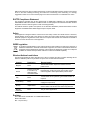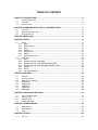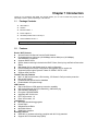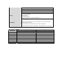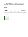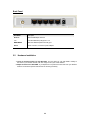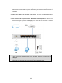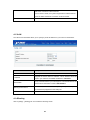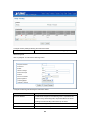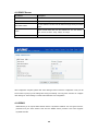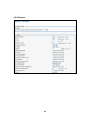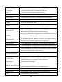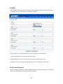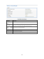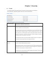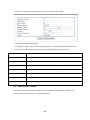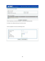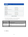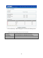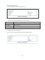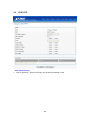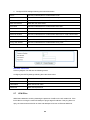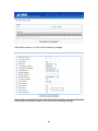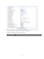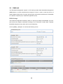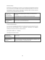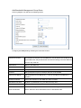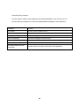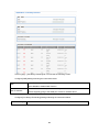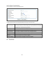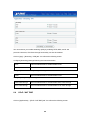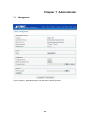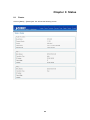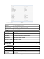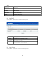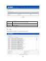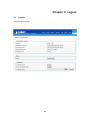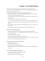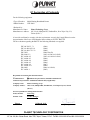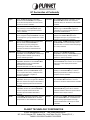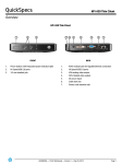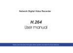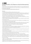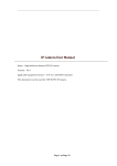
1
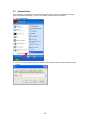
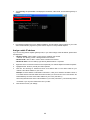
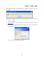
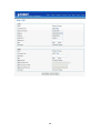
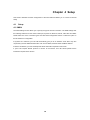
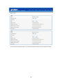
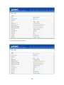
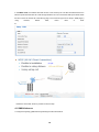
802.11N VPN Broadband Router VRT-420N Copyright Copyright 2011 by PLANET Technology Corp. All rights reserved. No part of this publication may be reproduced, transmitted, transcribed, stored in a retrieval system, or translated into any language or computer language, in any form or by any means, electronic, mechanical, magnetic, optical, chemical, manual or otherwise, without the prior written permission of PLANET. PLANET makes no representations or warranties, either expressed or implied, with respect to the contents hereof and specifically disclaims any warranties, merchantability or fitness for any particular purpose. Any software described in this manual is sold or licensed "as is". Should the programs prove defective following their purchase, the buyer (and not this company, its distributor, or its dealer) assumes the entire cost of all necessary servicing, repair, and any incidental or consequential damages resulting from any defect in the software. Further, this company reserves the right to revise this publication and to make changes from time to time in the contents hereof without obligation to notify any person of such revision or changes. All brand and product names mentioned in this manual are trademarks and/or registered trademarks of their respective holders. Federal Communication Commission Interference Statement This equipment has been tested and found to comply with the limits for a Class B digital device, pursuant to Part 15 of FCC Rules. These limits are designed to provide reasonable protection against harmful interference in a residential installation. This equipment generates, uses, and can radiate radio frequency energy and, if not installed and used in accordance with the instructions, may cause harmful interference to radio communications. However, there is no guarantee that interference will not occur in a particular installation. If this equipment does cause harmful interference to radio or television reception, which can be determined by turning the equipment off and on, the user is encouraged to try to correct the interference by one or more of the following measures: 1. Reorient or relocate the receiving antenna. 2. Increase the separation between the equipment and receiver. 3. Connect the equipment into an outlet on a circuit different from that to which the receiver is connected. 4. Consult the dealer or an experienced radio technician for help. FCC Caution: To assure Confirmed compliance, (example-use only shielded interface cables when connecting to computer or peripheral devices) any changes or modifications not expressly approved by the party responsible for compliance could void the user’s authority to operate the equipment. This device complies with Part 15 of the FCC Rules. Operation is subject to the Following two conditions: (1) This device may not cause harmful interference, and (2) this Device must accept any interference received, including interference that may cause undesired operation. Federal Communication Commission (FCC) Radiation Exposure Statement This equipment complies with FCC radiation exposure set forth for an uncontrolled environment. In order to avoid the possibility of exceeding the FCC radio frequency exposure limits, human proximity to the antenna shall not be less than 20 cm (8 inches) during normal operation. CE mark Warning This is a class B device, in a domestic environment; this product may cause radio interference, in which case the user may be required to take adequate measures. Energy Saving Note of the Device This power required device does not support Stand by mode operation. For energy saving, please remove the DC-plug or push the hardware Power Switch to OFF position to disconnect the device from the power circuit. Without remove the DC-plug or switch off the device, the device wills still consuming power from the power circuit. In the view of Saving the Energy and reduce the unnecessary power consuming, it is strongly suggested to switch off or remove the DC-plug for the device if this device is not intended to be active. R&TTE Compliance Statement This equipment complies with all the requirements of DIRECTIVE 1999/5/CE OF THE EUROPEAN PARLIAMENT AND THE COUNCIL OF 9 March 1999 on radio equipment and telecommunication terminal Equipment and the mutual recognition of their conformity (R&TTE). The R&TTE Directive repeals and replaces in the directive 98/13/EEC (Telecommunications Terminal Equipment and Satellite Earth Station Equipment) As of April 8, 2000. Safety This equipment is designed with the utmost care for the safety of those who install and use it. However, special attention must be paid to the dangers of electric shock and static electricity when working with electrical equipment. All guidelines of this and of the computer manufacture must therefore be allowed at all times to ensure the safe use of the equipment. WEEE regulation To avoid the potential effects on the environment and human health as a result of the presence of hazardous substances in electrical and electronic equipment, end users of electrical and electronic equipment should understand the meaning of the crossed-out wheeled bin symbol. Do not dispose of WEEE as unsorted municipal waste and have to collect such WEEE separately. Wireless National restrictions This device is intended for home and office use in all EU countries (and other countries following the EU directive 1999/5/EC) without any limitation except for the countries mentioned below: Country Restriction Reason/remark Bulgaria None General authorization required for outdoor use and public service France Outdoor use limited to 10 mW e.i.r.p. within the band 2454-2483.5 MHz Italy None If used outside of own premises, general authorization is required Luxembourg None General authorization required for network and service supply(not for spectrum) Norway Implemented This subsection does not apply for the geographical area within a radius of 20 km from the centre of Ny-Ålesund Russian Federation None Only for indoor applications Military Radiolocation use. Refarming of the 2.4 GHz band has been ongoing in recent years to allow current relaxed regulation. Full implementation planned 2012 Revision User’s Manual for PLANET 802.11n VPN Broadband Router Model: VRT-420N Rev: 1.0 (June 2011) TABLE OF CONTENTS CHAPTER 1 INTRODUCTION.........................................................................................................6 1.1 1.2 1.3 PACKAGE CONTENTS .........................................................................................................6 FEATURES .........................................................................................................................6 SPECIFICATION ..................................................................................................................7 CHAPTER 2 HARDWARE INSTALLATION / NETWORK SETUP .................................................9 2.1 2.2 2.3 OUTLOOK ..........................................................................................................................9 HARDWARE INSTALLATION ................................................................................................10 NETWORK SETUP .............................................................................................................12 CHAPTER 3 WEB LOGIN .............................................................................................................14 CHAPTER 4 SETUP ......................................................................................................................16 4.1 SETUP .............................................................................................................................16 WAN..........................................................................................................................16 WAN Advance...........................................................................................................19 LAN ...........................................................................................................................21 Routing......................................................................................................................21 DHCP Server ............................................................................................................24 DDNS........................................................................................................................24 MAC Address Clone .................................................................................................26 4.2 WIRELESS .......................................................................................................................26 4.2.1 Basic .........................................................................................................................26 4.2.2 Wireless security mode WEP ...................................................................................27 4.2.3 Wireless security mode WPA PSK/WPA2 PSK ........................................................28 4.2.4 Wireless security mode WPA Radius/WPA2 Radius ................................................28 4.2.5 Advance ....................................................................................................................29 4.2.6 WDS..........................................................................................................................31 4.2.7 Universal Repeater ...................................................................................................31 4.1.1 4.1.2 4.1.3 4.1.4 4.1.5 4.1.6 4.1.7 CHAPTER 5 SECURITY ................................................................................................................33 5.1 5.2 5.3 5.4 5.5 5.6 5.7 5.8 FIREWALL ........................................................................................................................33 ACCESS CONTROL ...........................................................................................................34 MAC ACCESS CONTROL ..................................................................................................35 OPENDNS ......................................................................................................................37 WEB FILTER ....................................................................................................................38 VPN PPTP .....................................................................................................................41 VPN IPSEC .....................................................................................................................42 BWM QOS......................................................................................................................46 CHAPTER 6 APPLICATION SETTINGS .......................................................................................50 6.1 6.2 6.3 6.4 APPLICATION SETTINGS ..............................................................................................................50 VIRTUAL HOST ............................................................................................................................52 STREAM VPN .............................................................................................................................53 UPNP / NAT PMP......................................................................................................................54 CHAPTER 7 ADMINISTRATOR ....................................................................................................56 7.1 7.2 7.3 MANAGEMENT..................................................................................................................56 SYSTEM UTILITY ..............................................................................................................57 TIME................................................................................................................................59 CHAPTER 8 STATUS ....................................................................................................................62 8.1 ROUTER ...........................................................................................................................62 8.2 8.3 8.4 USER/DHCP ....................................................................................................................64 USER/ CURRENT ...............................................................................................................64 LOG.................................................................................................................................65 CHAPTER 9 LOGOUT.................................................................................................................. 67 9.1 LOGOUT ..........................................................................................................................67 CHAPTER 10 TROUBLESHOOTING........................................................................................... 68 Chapter 1 Introduction Thank you for purchasing VRT-420N. This manual guides you on how to install and properly use the VRT-420N in order to take full advantage of its features. 1.1 Package Contents VRT-420N x 1 Antenna Ethernet Cable x 1 Power Adapter x 1 CD-ROM (included user’s manual) x 1 Quick Installation Guide x 1 Note: 1.2 If any of the above items are missing, please contact your supplier for support. Features Router / NAT Features Access Private LAN Servers from the Public Network Equipped with three LAN ports (10/100Mbps) and two WAN port (10/100Mbps), Auto-MDI/MDI-X supported Supports DHCP Server System status monitoring includes Active DHCP Client, Security Log and Device/Connection Status Web-based GUI for and Wizard setup for easily configuration Remote Management allows configuration and upgrades from a remote site Supported Internet types: Dynamic / Static IP / PPPoE / PPTP / L2TP Supports UPnP function Firewall / Security Features MAC / IP filter access control, URL blocking ; SPI firewall + DoS prevention protection Built in NAT firewall Predefined/User-defined service database Enable/disable VPN pass-through VPN Features Site-to-site/Client-to-VPN gateway connection capability IKE Keying Methods: Auto (Pre-shared Key), Manual Keying Authentication: MD5/SHA-1 Encryption: DES/3DES/AES Adjustable IKE SA Life time PPTP VPN tunnels : 10 IPsec VPN tunnels : 25 Load balance Multi-WAN bandwidth aggregation Round Robin Weighted Round Robin Multi-WAN failover WAN failure detection Wireless Features IEEE 802.11n wireless technology compliant with 802.11b/g standard Supports Wi-Fi Protected Setup (WPS) 1.3 Advanced security: 64/128-bit WEP, WPA –TKIP(PSK), WPA2-AES(PSK), 802.1x Max WDS mode link cloud is set up to 4 sets. Multiple SSID (Two SSID )and hidden SSID broadcasting Specification Product Model Hardware Standard Signal Type Modulation WAN Port LAN Port Antenna connector LED Indicators Data Encryption Output Power Data Rate N Data Rate Receiver Sensitivity 802.11n VPN Broadband Router VRT-420N IEEE 802.11b/g, 802.11n Draft 2.0, IEEE802.3u 11b mode: DSSS 11g mode: OFDM 11n mode: OFDM, MIMO 802.11b: DBPSK, DQPSK, CCK 802.11g: BPSK, QPSK, 16QAM, 64QAM 802.11n: BPSK, QPSK, 16QAM, 64QAM 2 x 10/100Base-TX, Auto-MDI/MDI-X 3 x 10/100Base-TX, Auto-MDI/MDI-X 1 x Detachable dipole 3 dBi Dipole Antenna PWR* 1, WLAN* 1, WAN * 2, LAN * 3 64 bit / 128 bit WEP, WPA-PSK, WPA, WPA2, 802.1x encryption 11b: 17 dBm 11g: 15 dBm 11n: 15dBm IEEE 802.11b: 11/5.5/2/1Mbps IEEE 802.11g: 54/48/36/24/18/12/9/6Mbps Please check Table (1) 11n 20/40MHz MCS7 ,10% PER, -67±2dBm 54Mbps OFDM, 10% PER, -72±2dBm 11Mbps CCK, 8% PER, -88±2dBm Software Router Feature Wireless Feature VPN Access Private LAN Servers from the Public Network Equipped with three LAN ports (10/100Mbps) and two WAN port (10/100Mbps), Supported Internet types: Dynamic / Static IP / PPPoE / PPTP / L2TP 802.1D ( Spanning Tree Protocol ) DHCP Server / Client UPnP and DDNS DMZ and Virtual Server SNTP Static Routing IEEE 802.11n wireless technology compliant with 802.11b/g standard Supports Wi-Fi Protected Setup (WPS) Advanced security: 64/128-bit WEP, WPA –TKIP(PSK), WPA2-AES(PSK), 802.1x Max WDS mode link cloud is set up to 4 sets. Multiple SSID (Two SSID )and hidden SSID broadcasting Site-to-site / Client-to-VPN gateway connection capability IKE Keying Methods: Auto (Pre-shared Key), Manual Keying Authentication: MD5/SHA-1 Encryption: DES/3DES/AES Adjustable IKE SA Life time PPTP VPN tunnels : 10 IPsec VPN tunnels : 25 Session MPLANETum Clients Virtual Host Port forwarding rule Security Management 15000 253 32 64 Built-in NAT Firewall MAC / IP/ Port Filtering Content Filtering SPI Firewall support Password protection for system management Web-based configuration System status monitoring includes Active DHCP Client, Security Log and Device/Connection Status Web-based GUI for and Wizard setup for easily configuration Remote Management allows configuration and upgrades from a remote site N Data Rate Table (1) MCS Index 0 1 2 3 4 5 6 7 HT20 HT40 Data rate (Mbps) @ 400ns GI 7.2 14.4 21.7 28.9 43.3 57.8 65.0 72.2 15.0 30.0 45.0 60.0 90.0 120.0 135.0 150.0 Chapter 2 Hardware Installation / Network Setup Please follow the below instruction to build the wireless network connection between VRT-420N and your computers. 2.1 Outlook Front Panel WLAN ON/OFF & WPS Button Active Time WLAN On/Off Press for less than 3 seconds for disable wireless configuration WPS button Press for less than 3 seconds for WPS configuration Reset Default Press the WPS and WLAN buttons for longer than 3 seconds to the factory default setting Back Panel Item Name Description Antenna Attached 3dBi dipole antenna. 1 -3 Local Area Network (LAN) ports 1 to 3. WAN1/WAN2 Wide Area Network (WAN / Internet) port. Power Power connector, connects to power adapter. 2.2 Hardware Installation 1. Locate an optimum location for the VRT-420N. The best place for your VRT-420N is usually at the center of your wireless network, with line of sight to all of your mobile stations. 2. Adjust the antennas of VRT-420N. Try to adjust them to a position that can best cover your wireless network. The antenna’s position will enhance the receiving sensitivity. 10 3. Connect all of your network devices to LAN port of VRT-420N. Connect all your computers, network devices (network-enabled consumer devices other than computers, like game console, or switch / hub).Connect one of the LAN ports on VRT-420N to your LAN switch/hub or a computer with a RJ-45 cable. 4. Plug in power adapter and connect to power source. After power on, VRT-420N will start to operate. 5. Please check all LEDs on the front panel. ‘Status’ LED should be steadily on. WAN and LAN LEDs should be on if the computer / network device connected to the respective port of the router is powered on and correctly connected. If PWD LED is not on, or any LED you expected is not on, please recheck the cabling, or jump to ‘Troubleshooting’ for possible reasons and solution. Note: 1. ONLY use the power adapter supplied with the VRT-420N. Otherwise, the product may be damaged. 2. If you want to reset VRT-420N to default settings, press and hold the WLAN ON/OFF + USB Eject button over 30 seconds and release. And then wait for VRT-420N restart. 11 2.3 Network Setup After you install your VRT-420N, the TCP/IP settings should be set to obtain an IP address from a DHCP server (VRT-420N) automatically. To verify your IP address, please follow the steps below: 1. Click on Start > Run. 2. In the run box type “cmd” and click OK. (Windows Vista users type cmd in the Start .Search box.)At the prompt. 12 3. Type “ipconfig” and press Enter. It will display the IP address, subnet mask, and the default gateway of adapter. 4. If the address is 0.0.0.0, check your adapter installation, security settings, and the settings on your router. Some firewall software programs may block a DHCP request on newly installed adapters. Assign a static IP address If you are not using a DHCP capable gateway/router, or you need to assign a static IP address, please follow the steps below: 1. - Windows Vista® - Click on Start > Control .Panel > Network .and .Internet >Network .and .Sharing .Center > Manage Network Connections. - Windows® XP - Click on Start > Control .Panel > Network Connections. - Windows® 2000 - From the desktop, right-click My Network Places > Properties. 2. Right-click on the Local Area Connection which represents your network adapter and selects Properties. 3. Highlight Internet .Protocol. (TCP/IP) and click Properties. 4. Click Use .the .following .IP .address and enter an IP address that is on the same subnet as your network or the LAN IP address on your router. Example: If LAN IP address of VRT-420N is 192.168.0.1, make your IP address 192.168.0.X where X is a number between 2 and 99. Make sure that the number you choose is not in use on the network. Set Default Gateway the same as the LAN IP address of your router (192.168.0.1). Set Primary DNS the same as the LAN IP address of your router (192.168.0.1). The Secondary DNS is not needed or you may enter a DNS server from your ISP. 5. Click OK twice to save your settings. 13 Chapter 3 Web Login We suggest manage the VRT-420N. In the browser IE version 7 or later version. VRT-420N with an assigned IP address allows you to monitor and configure via web browser (e.g., MS Internet Explorer or Netscape). 1. Open your web browser. 2. Enter the IP address of your VRT-420N in the address field (default IP address is http://192.168.0.1). 3. Please enter your User Name and Password in the dialog box. Default User Name and Password are both “admin”. Click OK. 4. Then you will see the VRT-420N HOME screen as below. 14 15 Chapter 4 Setup This section describes the basic configuration of the VRT-420N and allows you to connect to Internet easily. 4.1 Setup 4.1.1WAN The WAN Settings screen allows you to specify the type of Internet connection. The WAN settings offer the following selections for the router’s WAN port, Dynamic IP, Static IP, PPPoE, VPN client and WISP. Please select one of the connection types and click “More Configuration” button or select the option on the left window for configuration. If Dynamic IP is selected, your ISP will automatically give you an IP address. Some ISP’s may also require that you fill in additional information such as Host Name, Domain Name and MAC address. If Static IP is selected, your ISP should provide all the information required in this screen. If you’re ISP requires PPPoE protocol to connect to the Internet. Your ISP should provide all the information required in this section. 16 If you choose the VPN Client option, you will see the following PPTP and L2TP settings information. 17 Select PPTP if your ISP requires the PPTP protocol to connect to the Internet. Your ISP should provide all the information required in this section. 18 In this WISP mode, the wireless client will connect to ISP access point. The NAT is enabled and PCs in Ethernet ports share the same IP to ISP through wireless LAN. You must set the WAN port to WISP mode first and connect to the ISP AP in Site-Survey page. The connection type can be setup in WAN page by using PPPOE, DHCP client, PPTP IP. Please the Click “Next” button to proceed to the next step. 4.1.2WAN Advance 1.Configure the [Setup] -[WAN Advance] following the instructions below. 19 client or static Parameters Description Detection Interval Load balance detection interval. (seconds) Connection mode Choose Always on/Backup to define this WAN is for load balance always on, or just for backup. Backup WAN None Load Balance Weight The priority is set from 1 to 10. “1” indicates the lowest priority, and “10” indicates the highest. The system would route according to the ratio of priority. Wait Time The time to re-send the request.(seconds) External Connection Detection Choose Enable/Disable to enable/disable connection detection. Connection Detection Threshold The system will generate a PING packet to detect whether the connection is still connected. If the Host is not response for this threshold value, the system is considered to be WAN lost. Detection time out How long Load balance detection will seems time out. Detection Type If gateway is chosen, the system will generate a PING packet to detect 20 whether the connection is still connected. If custom host is chosen, the system will generate an ARP broadcast request to detect whether the connection is still connected. Custom Detection Host Enter the IP address or domain name of the host to be detected. 4.1.3LAN The LAN Port screen below allows you to specify a private IP address for your router’s LAN interface. Parameters Description Internal IP address Please input the IP address of this router. Designate the Access Point’s IP Address. This IP Address should be IP Address unique in your network. The default IP Address is 192.168.0.1. Specify a Subnet Mask for your LAN segment. The Subnet Mask of the Subnet Mask Access Point is fixed and the value is 255.255.255.0. If it is enabled, this router will use the spanning tree protocol to prevent Spanning Tree Protocol from network loop happened in the LAN ports. MTU MPLANETum Transmission Unit 4.1.4Routing Click on [Setup] – [Routing] tab. You will see the following screen. 21 Configure Security Settings following the instructions below. Routing Choose Enable/Disable to enable/disable routing policy. Add Routing Rule Click on [Add] tab. You will see the following screen. Configure the Routing rule following the instructions below. Parameters Description Sequence Number This defines the sequence of the Routing rules. If a packet fits the conditions set by the Routing rules, the packet will then be sorted according to the first Routing rule from the top of the list. Rule Name Name of the Routing rule. Enable Enable/Disable this Routing rule 22 Internal IP Range Set up the internal IP range for this ACL rule. External IP Range Set up the external IP range for this ACL rule. Protocol Set up the protocol (TCP or UDP) for the ACL to be enabled. Service Port Range Set up the Service Port Range (e.g., HTTP is TCP/80) for the ACL to be enabled. External Interface Please select which External Interface (WAN1 or WAN2) you want for a packet to be routed, IF the packet fits the condition of this Routing rule. Routing Gateway Set up routing gateway, (default / static), if static gateway been selected, please assign the gateway IP address in blow. Gateway IP address For static routing gateway. For example: Rule Name SMTP outgoing routing Enable Enable Internal IP Range Blank (applied to all) External IP Range Blank (applied to all) Protocol TCP Service Port Range 25:25 (SMTP Port:25) External Interface WAN1 Rule Name HTTP outgoing routing Enable Enable Internal IP Range Blank (applied to all) External IP Range Blank (applied to all) Protocol TCP Service Port Range 80:80 (HTTP Port:80) External Interface WAN 2 23 4.1.5DHCP Server Parameters Description DHCP Server Enable or disable the DHCP Server. DHCP Start IP Address The DHCP starting IP addresses offered by the DHCP Server. The mPLANETum number of the IP addresses supported by the DHCP Max DHCP Clients server Please choose lease time from the selection list. You can choose 1 Lease Hour, 3 Hours, 6 Hours, 1 Day, 3 Days, or 7 Days. Domain Please enter the domain name. After configuration complete, please click “Save Settings” button to save the configuration. Then you will see a screen to prompt you the settings are saving successfully. You may press “Confirm” for configure other settings or “Save Settings” to restart VRT-420N with new configuration. 4.1.6DDNS DDNS allows you to map the static domain name to a dynamic IP address. You must get an account, password and your static domain name from the DDNS service providers. This router supports DynDNS and TZO. 24 Parameters Description DDNS Service Enable/Disable the DDNS function of this router. DDNS Type Select a DDNS service provider. The default setting is “DynDNS”. User name Your static domain name that use DDNS. Password The password you set for the DDNS service account above. Host Name The account that your DDNS service provider assigned to you. 25 4.1.7MAC Address Clone To connect to Internet, your ISP will require a MAC address from your PC. Type in this MAC address in this section or use the “Clone MAC Address” button to replace the WAN port MAC address with the your PC’s. To find out the PC’s MAC address, see Appendix A. (also see Glossary for an explanation on MAC address). 4.2 Wireless 4.2.1Basic Multiple SSIDs (VRT-420N Max support the five SSID) allow the ability for separate security mode and key settings to be set by users for both convenience and increased protection. Users are able to configure their network devices to access the first SSID with the WPA2 PSK (Pre-Shared Key) and secret key, whilst share the second SSID with WEP and the periodically changed key for visitors. In addition, users are able to isolate these SSIDs to avoid malicious attacks and prevent certain access for visitors using the second SSID. This then provides users an extremely convenient approach to share the wireless access, provide access internet access for visitors, while possessing a strong security protection system at all times. 26 4.2.2Wireless security mode WEP When you select 64-bit or 128-bit WEP key, you have to enter WEP keys to encrypt data. You can generate the key by yourself. You can enter four WEP keys and select one of them as default key. Then the access point will just allow the clients that with the same encryption keys connected. 27 4.2.3Wireless security mode WPA PSK/WPA2 PSK Wi-Fi Protected Access (WPA) is an advanced security standard. You can use a pre-shared key to authenticate wireless stations and encrypt data during communication. It uses TKIP or CCMP (AES) or Mixed mode (TKIP+AES) to change the encryption key frequently. So the encryption key is not easy to be broken by hackers. This can improve security very much. 4.2.4Wireless security mode WPA Radius/WPA2 Radius You can use a RADIUS server to authenticate wireless stations and provide the session key to encrypt data during communication. It uses TKIP or CCMP (AES) to change the encryption key frequently. 28 4.2.5Advance 29 Region Choose the region you are currently located. Fragmentation Enter the fragmentation bytes. The default value is 2346 bytes. RTS Enter the RTS seconds. The default value is 2347 seconds. DTim Enter the DTim seconds. The default value is 1. Beacon Interval Enter the interval to send a beacon. The default value is 100 milliseconds. Header Preamble Choose Long or Short header preamble. TxMode Choose different transmission mode. MPDU data length. The transmission rate is increase when you choose a larger MPDU number, but usually the max value will be 4 in the wireless card A kind of packet aggregation method, it can improve the transmission efficiency. MSDU Aggregate Please make sure you Wireless card has this function supported. Some 802.11g wireless card can supported this mode, and the transmission rate can Tx Burst be increased when enable this function. An aggregation method like A-MSDU, it can improve the transmission efficiency. Packet Aggregate Please make sure you Wireless card has this function supported. HT Control Field Choose Enable/Disable. It is useful when you need to debug the wireless network Reverse Direction Grant Choose Enable/Disable. The response time can be shorter when enable this function. Choose Enable/Disable. The function is use to dynamically change the modulation Link Adapt and encode mechanism between wireless devices. Choose Enable/Disable. Short GI can improve some transmission rate, but with less Short Guard Interval (SGI) immunity when interference exist. Choose Mixed mode or Greenfield. You may choose Greenfield mode to increase the Operation Mode transmission rate when you using 802.11n wireless network only. HT Band Width Using HT20MHz or HT20/40MHz Choose Enable/Disable. If your Wifi Card supported Block Ack mechanism, it can Block Ack Setup Automatically improve the data transmission efficiency when enable this function. Block Ack Window Size Specify a Block Ack window size Reject Block Ack Choose Enable to reject the request of BA from other Wireless device MCS Select transmission (connection) speed. 30 4.2.6WDS WDS (Wireless Distributed System) enables the wireless bridging amongst several wireless devices. The bridged devices are identified by the WDS MAC addresses. *Please make sure of the following settings in order to allow WDS to work effectively: (1) WDS bridged devices must use the same radio channel. (2) WDS bridged devices must use the same encryption mode and encryption keys. Please Note: If one of the above fails, WDS devices cannot communication with each other. 4.2.7Universal Repeater Universal Repeater enables the wireless bridging amongst several wireless devices. The bridged devices are identified by the Target SSID and MAC addresses. 31 Parameter Description Universal Repeater Enable/Disable the Universal Repeater Mode function of this router. Mode In “Universal Repeater mode”, this device can act as a station to connect to Target SSID a Root AP. You should enter the SSID of the Root AP here. Target BSSID Please assign the root AP MAC address. (MAC) Wireless Channel Universal repeater wireless channel. Extension Channel Select extension is Above/ Blow. Security Mode Please choose the WEP, WPA PSK, or WPA2 PSK mode option. 32 Chapter 5 Security 5.1 Firewall VRT-420N provides extensive firewall protection by restricting connection parameters, thus limiting the risk of hacker attack, and defending against a wide array of common Internet attacks. Configure Security Settings following the instructions below. SPI Firewall Protection Select Enable to enable SPI Firewall Protection. Select Disable to disable SPI Firewall Protection. TCP SYN DoS Protection Check to enable TCP SYN DoS Protection. Uncheck to disable TCP SYN DoS Protection. TCP SYN DoS attack sends a flood of TCP/SYN packets. Each of these packets are like a connection request, causing the server to consume computing resources (e.g. memory, CPU) to reply and to continuously wait for the incoming packets. Without TCP SYN Dos Protection, the resources in the server will be easily consumed completely. This will then consequently result in the dysfunction of the server. VRT-420N is able to detect TCP SYN DoS attacks and limits the resource consumption by lowering the incoming request rate by fast recycling the resource. ICMP Protection Broadcasting Check to enable ICMP Broadcasting Protection. Uncheck to disable ICMP Broadcasting Protection. ICMP broadcasting attack is a type of DoS attacks. A flood of ICMP broadcasting packets is generated and sent to a server. Consequently, this server will suffer from a huge amount of interruptions and consumption of computing resources. VRT-420N is able to stop responding to ICMP broadcasting echo packets in order to avoid a potential ICMP broadcasting DoS attack. 33 ICMP Redirect Protection Check to enable ICMP Redirect Protection. Uncheck to disable ICMP Redirect Protection. An ICMP redirect message is a way to change the existing routing path. Generally, ICMP redirect packets should not be sent, and so when there is the occurrence that ICMP redirect packets are sent, it is important to note that it is very likely to be used as a means for a network attack. Broadcast Storming Check to enable Broadcast Storming Protection. Uncheck to disable Broadcast Storming Protection. A state in which a message that has been Broadcast across a network results in even more responses, and each response results in still more responses in a snowball effect. A severe broadcast storm can block all other network traffic, resulting in a network meltdown. Broadcast storms can usually be prevented by carefully configuring a network to block illegal broadcast messages. 5.2 Access Control This section shows how to setup the Broadband router’s system Time Zone, Password and Remote Management Administrator. Click on [Security] – [ACL] tab. You will see the following screen. 34 Please do not change the parameters unless you wish to customize it by yourself. Example: Filter and block MSN usage. For example, a company does not wish to allow employees to use MSN. The system administrator can set up an ACL action: rejecting the traffic going out to External IP Range at 207.46.110.*/24. Rule Name MSN Blocking Rule Enable Enable External Interface * (All complies) Internal IP Range Keep it blank (All complies) External IP Range 207.46.110.1:207.46.110.1.254 (IP address range for MSN server) Protocol TCP Service Port Range Keep it blank (All complies) Action DENY 5.3 MAC Access Control The Time Zone allows VRT-420N to allocate its time on the settings configured here; it will affect log display functions such as Security Log and Firewall settings. 35 1.Click on [Security] – [Access Control] tab. You will see the following screen. 2.Configure ACL Settings following the instructions below. 3.Click on [Add] tab. You will see the following screen. 36 Sequence Number This defines the sequence (priority) of all the MAC ACL actions. Rule Name Name of the MAC access rule. MAC Set up the MAC Address to which you would like to enable the MAC ACL action. Action Choose ALLOW/DENY to ALLOW/DENY ACL Enable Enable/Disable this MAC access rule Static ARP Enable Enable/Disable this Static ARP rule Static DHCP Enable Enable/Disable this Static DHCP rule IP The IP address corresponds to static ARP or static DHCP. MAC Access Control Choose Enable/Disable to enable/disable MAC access Control Default MAC Access The default ACL action of the ACL rules. When you add the individual rules, it can Control Action be viewed as exceptions and take effects relating to the default action. If the action of the adding rule is the same as the default action, then this rule will not work. 4.Example: Bind IP to a MAC If users need to bind an IP to a specified MAC (network device), one can follow the settings as below. Sequence Number User1 Rule Name Enable MAC 00:30:4F:55:66:77 Action Allow Access ACL Enable Enable Static ARP Enable Enable Static DHCP Enable Enable IP 192.168.0.100 5.4 OpenDNS 37 1. Click on [Security] – [OpenDNS] tab. You will see the following screen. 2. Configure OpenDNS Settings following the instructions below. OpenDNS Service Choose Enable/Disable to enable/disable OpenDNS OpenDNS Username Enter OpenDNS user name. OpenDNS Password Enter OpenDNS password. DNS Query Redirection to OpenDNS DNS Servers OpenDNS Label 5.5 Choose Enable/Disable to enable/disable the data flow redirect to the OpenDNS Server. Users can get advanced content filtering function through the setting Enter the OpenDNS Label WEB Filter 38 1. Click on [Security] – [Web Filtering] tab. You will see the following screen. 2. Configure Web Filtering Settings following the instructions below. Web Filtering Choose Enable/Disable to enable/disable Web Filtering ActiveX Filtering Choose Enable/Disable to enable/disable ActiveX Filtering Java/JavaScript Filtering Choose Enable/Disable to enable/disable Java/JavaScript Filtering Proxy Filtering Choose Enable/Disable to enable/disable Proxy Filtering 39 Added Web Filtering Rules 3. Click on [Add] tab. You will see the following screen. 4. Configure Web Filtering Settings following the instructions below Sequence Number This defines the sequence (priority) of all the Web Filtering rules. Rule Enable Choose Enable/Disable to enable/disable Web Filtering rule Filter Keyword Enter the Keyword Filter Type Choose URL or Sever Action Select ALLOW / DENY。 5. Example: Block a URL with Keyword If one need to block sex related web page, can follow the settings as below 40 5.6 VPN PPTP VPN / PPTP Settings 1. Click on [Security] – [VPN / PPTP] tab. You will see the following screen. 41 2. Configure PPTP Settings following the instructions below. PPTP Choose Enable/Disable to enable/disable L2TP. MTU Enter MTU value. The default value is 1482 bytes. VPN Start IP Address Enter the VPN start IP address. The default value is 192.168.39.1. Max VPN Clients Enter the max VPN clients. Auto DNS Choose Enable/Disable to enable/disable Auto DNS. DNS Enter DNS server if you choose Disable for Auto DNS. CHAP Enable Choose Enable/Disable to enable/disable CHAP for VPN authentication. MSCHAP Enable Choose Enable/Disable to enable/disable MSCHAP for VPN authentication. MSCHAP2 Enable Choose Enable/Disable to enable/disable MSCHAP2 for VPN authentication. MPP128 Enable Choose Enable/Disable to enable/disable MPP128 encryption. Proxy ARP Enable Choose Enable/Disable to enable/disable Proxy ARP. NAT Enable Choose Enable/Disable to enable/disable NAT. Add VPN / PPTP Rule Click on [Add] tab. You will see the following screen. Configure [Add PPTP] Settings following the instructions below. Sequence Number This defines the sequence of the PPTP rules. Rule Enable Enable/Disable this PPTP rule User Name Enter PPTP user name. Password Enter PPTP password. 5.7 VPN IPSec WAN failure detection works by detecting the presence of traffic on the 3G modem link. If the link is idle for too long the router will attempt to ping a target IP address. If the ping does not reply, the router assumes the link is down and attempts to fail over to Ethernet WAN link. 42 After add the option, you will see the following settings. After enable the Advance option, you will see the following settings. 43 Click on [Security] – [VPN / IPsec] tab. You will see the following screen. Configure IPsec Settings following the instructions below. IPsec Select Enable/Disable to enable/disable IPsec. 44 Configure [Add - IPsec] Settings following the instructions below. Sequence Number This defines the sequence of the IPsec rules. Connection Name Name of the IPsec rule. Rule Enable Enable/Disable this IPsec rule VPN Mode Net-to-Net or Road Warrior Local External Interface Choose the external WAN for the local VPN gateway. Local Internal IP Address Choose the subnet IP address for the VPN gateway. Local Netmask Choose the netmask for the local VPN gateway. Remote Gateway Enter the IP address or domain name of the remote VPN gateway. This option is needed in Net-to-Net mode. Remote Subnet IP Enter the subnet IP address of the remote VPN gateway. This option is needed in Net-to-Net mode. Remote Netmask Enter the subnet netmask of the remote VPN gateway. This option is needed in Net-to-Net mode. Connection Initiation Check the local VPN gateway to initiate the connection. This option is needed in Net-to-Net mode. IKE Key Mode PSK. Preshared Key Enter the preshared key. The key should be at least 8-digit ASCII string. DPD Enable “Dead Peer Detection” DPD Interval The interval time for DPD. DPD Timeout It takes how long the DPD will seem this connection timeout. Advanced Options Check it if you need to configure the advanced options. Phase 1 Mode Main. Phase 1 ID Enter the phase 1 ID. Phase 1 Lifetime Enter the phase 1 lifetime. This value is between 3600 and 28800 seconds. Phase 2 Lifetime Enter the phase 2 lifetime. This value is between 3600 and 28800 seconds. Phase 1 Authentication Choose the phase 1 authentication as MD5 or SHA1. Phase I Encryption Choose the phase 1 encryption as DES, 3DES or AES. Phase 1 Group Key Choose the phase 1 group key management as DH1, DH2 or DH5. A Traffic-Based Method of Detecting Dead IKE Peers Management Phase 2 Authentication Choose the phase 2 authentication as MD5 or SHA1. Phase 2 Encryption Choose the phase 2 encryption as DES, 3DES or AES. Phase 2 Group Key Choose the phase 2 group key management as DH1, DH2 or DH5. Management 45 5.8 BWM QoS The Bandwidth Management System in VRT-420N provides Static Bandwidth Management (SBM) feature to control the packet flow through the router in order to meet the service of quality. SBM provides users or groups with the option to allocate a fixed amount of bandwidth for a specific computer (IP) or a particular application (Port) BWM Settings The essential configuration needed by QoS is to specify accurately the bandwidth you have. QoS would then dispatch bandwidth according to this information. Please Note: Improper bandwidth assignment may cause QoS to work ineffectively. Click on [BWM] – [QoS] tab. You will see the following screen 46 Bandwidth Settings: Please adjust your bandwidth type according to your bandwidth (download/upload) subscribed from your ISP. Due to the unstable nature of network bandwidth supported by ISP, users are recommended to reserve a portion of bandwidth for buffering usage, and QoS would then arrange the reserved bandwidth under heavy traffic. Bandwidth Type (Download/Upload) Select the correct bandwidth type according to your Internet service subscription. If the bandwidth type is not available on the list, select Custom. Download Bandwidth Enter the value to customize download bandwidth. Upload Bandwidth Enter the value to customize upload bandwidth. Reserved Buffering Bandwidth Enter the value to provide bandwidth buffer. 5.Advanced Setting Example A user subscribed 10M/2Mbps bandwidth from ISP. After performing some speed test, the user found that the actual bandwidth is about 1135KByte/sec downloading and 200KByte/s uploading. We change the dimension in Kbps as follows, Upload Speed: 200KB/s x 8 = 1600Kbp/s The settings can be done as below, Bandwidth Type Select custom。 (Download/Upload) Upload Bandwidth Enter the value to 1600。 Reserved Buffering User can firstly set the value about 10% and adjust this value later. If your Bandwidth network is very stable, you could lower this value. 47 Add Bandwidth Management Group Rules Click on [Add] tab. You will see the following screen. Configure [Add SBM] Settings following the instructions below. Sequence Number This defines the sequence of the SBM rules. If a packet fits the conditions set by the SBM rules, the packet will then be sorted according to the first SBM rule from the top of the list. Rule Name Name of the SBM rule. Rule Enable Enable/Disable this SBM rule Internal IP Set up the internal IP for this SBM rule. Protocol Set up the protocol (TCP or UDP) for the ACL to be enabled. Service Port Range Set up the Service Port Range (e.g., HTTP is TCP/80) for the SBM to be enabled. External Interface Choice the interface for this SBM rule, WAN 1/ WAN2. Bandwidth Allocation By Ratio, by Bandwidth or by pre-defined Group rules Ratio The ratios of the whole upload bandwidth according to the External Interface. Utilize Bandwidth More Check this box if you wish to allow the traffic confirming this SBM rule to be than Guaranteed able to utilize the whole bandwidth when the bandwidth is idle. 48 Advanced Setting Example1 If a user needs to reverse some bandwidth for a specified application, such as VoIP, one can have the following configuration to reserve a 25Kbps/25Kbps bandwidth for VoIP application. Rule Name PLANET Rule Enable Check the box to enable this rule Internal IP Address Enter the IP address of the computer using P2P software Protocol Select * will apply this rule for both TCP and UDP protocols Service Port Range Left blank will applied to all service port Bandwidth Allocation Allocating the bandwidth by fixed value assignment Upload Enter the upload rate to 500 Kbps Utilize Bandwidth More Than Guaranteed Uncheck this box to reserve a fixed rate for this application. 49 Chapter 6 Application Settings 6.1 Application Settings The Status screen allows you to monitor the current status of your router. You can use the Status page to monitor the connection status of Applications Settings. By activating the port range forwarding function, remote users can access the local network via the public IP address. Users can assign a specific external port range to a local server. Furthermore, users can specify an internal port range associated in a port range forwarding rule. When VRT-420N receives an external request to access any one of the configured external ports, it will redirect the request to the corresponding internal server and change its destination port to one of the internal ports specified. Therefore, if users do not wish for destination port to be changed for a request, the internal port range should be left empty. By enabling DMZ Host Function, you can set up a DMZ host at a particular computer exposed to the Internet. In this way, some applications, especially online games (if the traffic port numbers of the applications are always changing), can be easily accessed. 50 Click on [App] – [Port Range Forward] tab. You will see the following screen. Configure [DMZ] Settings following the instructions below Select Enable to enable DMZ function. DMZ Select Disable to disable DMZ function. DMZ IP Address Enter the IP address of a particular host in your LAN which will receive all the packets originally going to the WAN port / Public IP address above. Configure [Port Range Forwarding] Settings following the instructions below Port Forwarding Select Enable / Disable to enable/disable Port Forwarding 51 Add Port Range Forwarding Rule Click on [Add] tab. You will see the following screen. Configure [Add Port Range Forwarding Rule] Settings following the instructions below This defines the sequences (priorities) of the port forwarding rules. If a packet fits Sequence Number the conditions setup by the port forwarding rules, the packet will then be forwarded according to the 1st rule from the top of the list. Rule Name Enter the name of the port forwarding rule. Rule Enable Check/Uncheck to enable/disable this port forwarding rule. External Interface Choose WAN1 or WAN2 as the External port forwarding interface. Protocol Choose TCP, UDP or TCP/UDP for the rule to be applied. External Port Range Set up the External Port Range for the rule to be applied. Internal IP Set up the Internal IP for the rule to be applied. Internal Port Range Set up the Internal Port Range for the rule to be applied. 6.2 Virtual Host 52 After enable the “add and modify” the function, WEB UI will show the following information. Sequence Number Please key the number Rule Name Please key the Name Rule Enable Enable/Disable the Rule External Interface Choice the interface for this rule. External IP Address Please key the WAN Port IP address Mapped LAN IP Address Please key the LAN Port IP address 6.3 Stream VPN 53 You can enhance your media streaming quality by enabling RTSP, MSS, and H.323 protocols. Moreover, VPN Pass-through functionality can also be enabled. Click on [App] – [Streaming / VPN] tab. You will see the following screen. Configure [Streaming] Settings following the instructions below. RTSP Select Enable/Disable to enable/disable RTSP MMS Select Enable/Disable to enable/disable MMS Configure [Video Conference] Settings following the instructions below H.323 Select Enable/Disable to enable/disable H.323 Configure [VPN] Settings following the instructions below IPSec Pass-through Select Enable/Disable to enable/disable IPSec Pass-through PPTP Pass-through Select Enable/Disable to enable/disable PPTP Pass-through 6.4 UPnP / NAT PMP Click on [Applications] – [UPnP / NAT-PMP] tab. You will see the following screen. 54 Configure [UPnP] Settings following the instructions below UPnP Select Enable/Disable to enable/disable UPnP NAT-PMP Select Enable/Disable to enable/disable NAT-PMP UPnP Port Enter the number for UPnP port. 55 Chapter 7 Administrator 7.1 Management Click on [Admin] – [Management] tab. You will see the following screen. 56 Configure [Administration Interface] Settings based on the instructions listed below. Language Select the language of administration Interface you wish to use. Maximum input is 36 alphanumeric characters (case sensitive) * Please change the administrator’s password if the remote Administrator Password management is enabled. Otherwise, a malicious user can access the management interface. This user can then have the ability to change the settings and damage your network access. Re-type Password Remote Management Management Port Enter the password again to confirm. Select Enable to enable Remote Management. Select Disable to disable Remote Management HTTP port which users can connect to. (default port is 8080) Configure [Configuration] Settings based on the instructions listed below Configuration Export Default Configuration Restore Configuration Import Click Export to save your current configuration settings in a file. Click Restore to recover the default system settings. Click Browse and Import to load previous configuration settings. Configure [Firmware] Settings based on the instructions listed below Firmware Upgrade 7.2 Click Browse and Upgrade to upgrade the firmware. System Utility Click on [Admin] – [System Utilities] tab. You will see the following screen. 57 58 Using the [ping] tool based on the instructions listed below Interface Select the interface that use to ping to, ie. WAN1,WAN2, LAN. Target Host Enter the IP address to ping to Number of Packets Specify the number of the ICMP packets to send out Ping Press the tab to start the “ping” actions Using the [ARPing] tool based on the instructions listed below Interface Select the interface that use to ARPing to, ie.WAN1,WAN2, LAN Target Host Enter the MAC address to ARPing to Number of Packets Specify the number of the ARP request packets to send out ARPing Press the tab to start the “ARPing” actions Using the [Trace Route] tool based on the instructions listed below Interface Select the interface that use to ARPing to, ie. WAN1, WAN2. Target Host Enter the destination IP address / domain name to trace Hop Count Specify the Hop number you need to trace Trace route Press the tab to start the “Trace Route” actions 7.3 Time Click on [Setup] – [Time] tab. You will see the following screen. 59 Configure [Time] Settings based on the instructions listed below Time Synchronization Time Server Time Zone Select Enable/Disable to enable/disable Time Synchronization Select Time Server according to your location. You can choose from Automatic, Asia, Europe, North America, South America, or Africa. Select Time Zone according to your location. (Daylight Saving Time has been calculated and included in the selection). Periodic Synchronization Select Enable/Disable to enable/disable Periodic Synchronization Daylight Saving Support Select Enable/Disable to enable/disable Daylight Saving Support. Synchronization interval Select from Every Hour, Every 6 Hours, Every 12 Hours, Every Day, and Every Week. Automatic Reboot Select Enable/Disable to enable/disable Automatic Reboot Reboot Interval Selected the reboot interval, Every week, Every day, Every hour Day Sunday-Saturday Hour 0-23 60 Minutes 0-59 61 Chapter 8 Status 8.1 Router Click on [Status] – [Router] tab. You will see the following screen. 62 Router Information Model Name Product model name is shown. Firmware Version The firmware version this device is running. Current Time Current system time LAN MAC Address MAC Address IP Address Internal IP Address Subnet Mask The number of subnet mask in the internal network DHCP Service DHCP service enabled or disabled DHCP Start IP Address DHCP Start IP address DHCP End IP Address DHCP End IP address The maximum IP addressed which can be assigned to PCs connecting to the Max DHCP Clients network Wireless Network Wireless Mode Access Point Wireless SSID SSID of this Wi-Fi station Wireless Channel Wireless Channel in use (default is 6) MAC Address MAC Address 63 WAN MAC Address MAC Address Connection Type The current connection type (PPPoE, Static IP, and DHCP) IP Address WAN IP Address Subnet Mask Number of subnet mask. Gateway IP address of the gateway 8.2 User/DHCP Click on [Status] – [DHCP] tab. You will see the following screen. Name DHCP client name IP Address IP address which is assigned to this client MAC Address MAC address of this client Expiration Time 8.3 The remaining time of the IP assignment User/ Current Click on [Status] – [Current] tab. You will see the following screen. 64 IP Address IP address assigned by Static ARP matching MAC Address MAC address in the Static ARP matching ARP Type Static or dynamic 8.4 Log Click on [Status] – [Log] tab. You will see the following screen. 65 Log Server Setting: Syslog server Remote IP Address Enable/Disable Sys log feature. Remote Sys-log server address Protocol What protocol you want to use for TCP/UDP. Remote port Sys-log remote port. 66 Chapter 9 Logout 9.1 Logout To logout the VRT-420N 67 Chapter 10 Troubleshooting If you found VRT-420N is working improperly or stop responding to you, please kindly read this troubleshooting first. Some problems can be solved by you within very short time! Please contacts with your local dealer if below methods are failed. Router is not responding to me when I want to access it by web browser. 1. Please check the connection of power cord and network cable of this router. All cords and cables should be correctly and firmly inserted to the router. 2. If all LEDs on this router are off, please check the status of A/C power adapter, and make sure it’s correctly powered. 3. You must use the same IP address section which router uses. 4. Are you using MAC or IP address filter? Try to connect the router by another computer and see if it works; if not, please restore your router to factory default settings (pressing ‘reset’ button for over 10 seconds). 5. Set your computer to obtain an IP address automatically (DHCP), and see if your computer can get an IP address. 6. If you did a firmware upgrade and this happens, contact your dealer of purchase for help. Why I can’t get connected to Internet? 1. Call your Internet service provide and check if there’s something wrong with their service. 2. If you just can’t connect to one or more website, but you can still use other internet services, please check URL/Keyword filter. 3. Try to reset the router and try again later. 4. Reset the device provided by your Internet service provider too. 5. Try to use IP address instead of hostname. If you can use IP address to communicate with a remote server, but can’t use hostname, please check DNS setting. Why I can’t locate my router by my wireless client? 1. ‘Broadcast ESSID’ set to off? 2. All two antennas are properly secured. 3. Are you too far from your router? Try to get closer. 4. Please remember that you have to input ESSID on your wireless client manually, if ESSID broadcast is disabled. File download is very slow or breaks frequently 1. Are you using QoS function? Try to disable it and try again. 2. Internet is slow sometimes, being patient. 3. Try to reset the router and see if it’s better after that. 68 4. Try to know what computers do on your local network. If someone’s transferring big files, other people will think Internet is really slow. 5. If this never happens before, call you Internet service provider to know if there is something wrong with their network. I can’t log onto web management interface: password is wrong 1. Make sure you’re connecting to the correct IP address of the router! 2. Password is case-sensitive. Make sure the ‘Caps Lock’ light is not illuminated. 3. If you really forget the password, do a hard reset. Router become hot 1. This is not a malfunction if you can keep your hand on the router’s case. 2. If you smell something wrong or see the smoke coming out from router or A/C power adapter, please disconnect the router and A/C power adapter from utility power (make sure it’s safe before you’re doing this!), and call your dealer of purchase for help. The date and time of all event logs are wrong 1. Adjust the internal clock of router. 69 EC Declaration of Conformity For the following equipment: *Type of Product: *Model Number: Multi-Homing Broadband Router VRT-420N *Produced by: Manufacturer‘s Name: Manufacturer‘s Address: Planet Technology Corp. 10F., No.96, Minquan Rd., Xindian Dist., New Taipei City 231, Taiwan (R.O.C.) is herewith confirmed to comply with the requirements set out in the Council Directive on the Approximation of the Laws of the Member States relating to 99/5/EC R&TTE. For the evaluation regarding the R&TTE the following standards were applied: EN 300 328 V1.7.1 EN 301 489-01V1.8.1 EN 301 489-17V1.3.2 EN 55022 EN 61000-3-3 IEC 61000-4-2 IEC 61000-4-3 IEC 61000-4-4 IEC 61000-4-5 IEC 61000-4-6 IEC 61000-4-11 EN 60950 IEC 60950-1 (2006) (2008) (2008) (2006 Class B) (1995+A1:2001+A2:2005) (1995+A1:1998+A2:2001) (2006) (2004) (2006) (2007) (2004) (2006+A11:2009) (2005) Responsible for marking this declaration if the: Manufacturer Authorized representative established within the EU Authorized representative established within the EU (if applicable): Company Name: Planet Technology Corp. Company Address: 10F., No.96, Minquan Rd., Xindian Dist., New Taipei City 231, Taiwan (R.O.C.) Person responsible for making this declaration Name, Surname Jonas Yang Position / Title : Product Manager Taiwan Place 28 March, 2011 Date Legal Singnature PLANET TECHNOLOGY CORPORATION e-mail: [email protected] http://www.planet.com.tw 11F, No. 96, Min Chuan Road, Hsin Tien, Taipei, Taiwan, R.O.C. Tel:886-2-2219-9518 Fax:886-2-2219-9528 EC Declaration of Conformity English Hereby, PLANET Technology Corporation, Lietuviškai kad Product Wi-Fi tenkina visus svarbiausius with the essential requirements and other relevant 1999/5/EC direktyvos reikalavimus ir kitas svarbias provisions of Directive 1999/5/EC. Česky Společnost PLANET Technology Corporation, nuostatas. Magyar kijelenti, hogy ez a Product Wi-Fi megfelel az základní požadavky a další příslušná ustanovení 1999/5/EK irányelv alapkövetelményeinek és a PLANET Technology Corporation, erklærer kapcsolódó rendelkezéseknek. Malti Hawnhekk, PLANET Technology Corporation, herved, at følgende udstyr Product Wi-Fi overholder jiddikjara li dan Product Wi-Fi jikkonforma de væsentlige krav og øvrige relevante krav i direktiv mal-ħtiġijiet essenzjali u ma provvedimenti oħrajn 1999/5/EF Deutsch A gyártó PLANET Technology Corporation, tímto prohlašuje, že tato Product Wi-Fi splňuje směrnice 1999/5/EC. Dansk Šiuo PLANET Technology Corporation,, skelbia, declares that this Product Wi-Fi is in compliance relevanti li hemm fid-Dirrettiva 1999/5/EC Hiermit erklärt PLANET Technology Corporation, Nederlands Hierbij verklaart , PLANET Technology orporation, dass sich dieses Gerät Product Wi-Fi in dat Product Wi-Fi in overeenstemming is met de Übereinstimmung mit den grundlegenden essentiële eisen en de andere relevante bepalingen Anforderungen und den anderen relevanten van richtlijn 1999/5/EG Vorschriften der Richtlinie 1999/5/EG befindet". (BMWi) Eesti keeles Käesolevaga kinnitab PLANET Technology Polski Corporation, oświadcza, że Product Wi-Fi spełnia Nõukogu direktiivi 1999/5/EC põhinõuetele ja wszystkie istotne wymogi i klauzule zawarte w muudele olulistele tingimustele. Ελληνικά Niniejszym firma PLANET Technology Corporation, et see Product Wi-Fi vastab Euroopa ΜΕ ΤΗΝ ΠΑΡΟΥΣΑ , PLANET Technology dokumencie „Directive 1999/5/EC”. Português PLANET Technology Corporation, declara que Corporation, ΔΗΛΩΝΕΙ ΟΤΙ ΑΥΤΟ Product Wi-Fi este Product Wi-Fi está conforme com os requisitos ΣΥΜΜΟΡΦΩΝΕΤΑΙ ΠΡΟΣ ΤΙΣ ΟΥΣΙΩΔΕΙΣ essenciais e outras disposições da Directiva ΑΠΑΙΤΗΣΕΙΣ ΚΑΙ ΤΙΣ ΛΟΙΠΕΣ 1999/5/CE. ΣΧΕΤΙΚΕΣ ΔΙΑΤΑΞΕΙΣ ΤΗΣ ΟΔΗΓΙΑΣ 1999/5/ΕΚ Español Por medio de la presente, PLANET Technology Slovensky Výrobca PLANET Technology Corporation, týmto Corporation, declara que Product Wi-Fi cumple deklaruje, že táto Product Wi-Fi je v súlade so con los requisitos esenciales y cualesquiera otras základnými požiadavkami a ďalšími relevantnými disposiciones aplicables o exigibles de predpismi smernice 1999/5/EC. la Directiva 1999/5/CE Français Par la présente, PLANET Technology Slovensko PLANET Technology Corporation, s tem potrjuje, Corporation, déclare que les appareils du Product da je ta Product Wi-Fi skladen/a z osnovnimi Wi-Fi sont conformes aux exigences essentielles et zahtevami in ustreznimi določili Direktive 1999/5/EC. aux autres dispositions pertinentes de la directive 1999/5/CE Italiano Con la presente , PLANET Technology Suomi PLANET Technology Corporation, vakuuttaa täten Corporation, dichiara che questo Product Wi-Fi è että Product Wi-Fi tyyppinen laite on direktiivin conforme ai requisiti essenziali ed alle altre 1999/5/EY oleellisten vaatimusten ja sitä koskevien disposizioni pertinenti stabilite dalla direttiva direktiivin muiden ehtojen mukainen. 1999/5/CE. Latviski Ar šo PLANET Technology Corporation, apliecina, Svenska Härmed intygar, PLANET Technology Corporation, ka šī Product Wi-Fi atbilst Direktīvas 1999/5/EK att denna Product Wi-Fi står i överensstämmelse pamatprasībām un citiem atbilstošiem noteikumiem. med de väsentliga egenskapskrav och övriga relevanta bestämmelser som framgår av direktiv 1999/5/EG. PLANET TECHNOLOGY CORPORATION e-mail: [email protected] http://www.planet.com.tw 10F., No.96, Minquan Rd., Xindian Dist., New Taipei City 231, Taiwan (R.O.C.) Tel:886-2-2219-9518 Fax:886-2-2219-9528