1
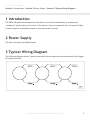
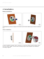
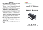
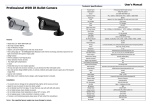
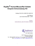
PBTA-200 User Manual
User Manual /
PBTA-200
Issue #1 Issue Date XX/XX/XXXX Revision #1
PBTA-200 User Manual
Contents /
Contents
2
Section 1 Introduction
3
Section 2 Power Supply
3
Section 3 Typical Wiring Diagram
3
Section 4 Installation
4
Section 5 Technical Specification
5
Issue #1 Issue Date XX/XX/XXXX Revision #1
PBTA-200 User Manual
Section 1 Introduction / Section 2 Power Supply / Section 3 Typical Wiring Diagram /
1 Introduction
The PBTA-200 push button temporary fire alarm is activated immediately by pressing the
“mushroom” button fixed to the front of the device. Once activated the unit will sound & flash.
It can be used as a standalone alarm or interconnected in series.
2 Power Supply
The unit is powered by 8 AA batteries.
3 Typical Wiring Diagram
The following diagram shows 3 units connected in series where one alarm activation will trigger
all connected units.
Fig.1
Issue #1 Issue Date XX/XX/XXXX Revision #1
3
PBTA-200 User Manual
4 Installation
Battery Installation
Fig.2
Fig.3
Install batteries as shown in figures 2 & 3 above (note that the battery sign is shown on battery
box).
Alarm Installation
Fig.4
Fig.5
It can be installed on boards, walls or wherever it can be hung (these should be places where
the unit is easily visible). Fix the screw according to figure 4 and complete the installation
according to figure 5.
4
Issue #1 Issue Date XX/XX/XXXX Revision #1
PBTA-200 User Manual
5 Technical Specification
Operating Voltage
8 x AA batteries (12V DC)
Average Current
10uA
Alarm Current
200mA
Sound Output
95 db @ 3m
Strobe Colour
Red
Operating Temperature
-10°C to +50°C
Minimum Continuous Temperature
0°C
Maximum Humidity
95% RH Non Condensing
Alarm Activation
Manual (press “mushroom” button)
Reset
Manual (twist “mushroom” button)
Number of Interlinked Units
32
IP Rating
IP35
Size, Width x Height x Diameter
230mm x 230mm x 104mm
Weight (Including Batteries)
650g (850g)
Issue #1 Issue Date XX/XX/XXXX Revision #1
5