1
HART® Field Device Specification
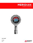
Meridian wiredHART
4320 Goldmine Rd.
Monroe, NC 28110
USA
®
HART is a registered trademark of the HART Communication Foundation
TABLE OF CONTENTS
1. Introduction ......................................................................................................................................5 1.1 Scope ....................................................................................................................................5 1.2 Purpose.................................................................................................................................5 1.3 Who should use this document? ..........................................................................................5 1.4 Abbreviations and definitions ..............................................................................................5 1.5 References ............................................................................................................................5 2. Device Identification........................................................................................................................6 3. Product Overview ............................................................................................................................6 4. Product Interfaces ............................................................................................................................6 4.1 Process Interface ..................................................................................................................6 4.1.1 Sensor Input Channels ..........................................................................................6 4.2 Host Interface .......................................................................................................................6 4.2.1 Analog Output 1: Gas Concentration....................................................................6 4.3 Local Interfaces, Jumpers and Switches ..............................................................................7 4.3.1 Local Controls and Displays .................................................................................7 4.3.2 Internal Jumpers and Switches .............................................................................7 5. Device Variables ..............................................................................................................................7 6. Dynamic Variables...........................................................................................................................7 7. Status Information............................................................................................................................7 7.1 Device Status .......................................................................................................................7 7.2 Extended Device Status .......................................................................................................8 7.3 Additional Device Status (Command #48) ..........................................................................8 8. Universal Commands .......................................................................................................................8 9. Common-Practice Commands .........................................................................................................8 9.1 Supported Commands ..........................................................................................................8 9.2 Burst Mode ..........................................................................................................................8 9.3 Catch Device Variable .........................................................................................................9 10. Device-Specific Commands...........................................................................................................10 10.1 Command #203: Read Transmitter Information ................................................................11 10.2 Command #204: Read Transmitter Alarm Parameters ......................................................12 Revision 1.0, Release Date: 30 August, 2013
Page 2 of 47
10.3 Command #205: Set Transmitter Alarm Parameters .........................................................13 10.4 Command #206: Read Transmitter Date & Time ..............................................................14 10.5 Command #207: Set Transmitter Date & Time .................................................................15 10.6 Command #208: Read Transmitter Editor Parameters ......................................................16 10.7 Command #209: Set Transmitter Editor Parameters .........................................................17 10.8 Command #210: Read Sensor Information General ..........................................................18 10.9 Command #211: Read Sensor Information Detailed .........................................................19 10.10 Command #212: Read Sensor Information Dates ..........................................................20 10.11 Command #213: Read Sensor Information Live ............................................................21 10.12 Command #214: Backup / Restore Transmitter Parameters ...........................................22 10.13 Command #220: Read Sensor Setup General .................................................................23 10.14 Command #221: Set Sensor Setup General ....................................................................24 10.15 Command #222: Read Sensor Setup Calibration............................................................26 10.16 Command #223: Set Sensor Setup Calibration...............................................................27 10.17 Command #224: Read Sensor Setup Alarms ..................................................................29 10.18 Command #225: Set Sensor Setup Alarms .....................................................................30 10.19 Command #226: Read Sensor Names.............................................................................32 10.20 Command #227: Set Sensor Names ................................................................................33 10.21 Command #228: Read Sensor Information Calibration..................................................34 10.22 Command #229: Zero and Span Sensors ........................................................................35 10.23 Command #230: Set System Inhibit ...............................................................................36 10.24 Command #231: Alarm Acknowledge ...........................................................................37 10.25 Command #230: Read Sensor Offline Settings ..............................................................38 10.26 Command #231: Set Sensor Offline ...............................................................................39 10.27 Command #234: Read Loop Trim Parameters ...............................................................40 10.28 Command #235: Set Loop Trim Parameters ..................................................................41 11. Performance ...................................................................................................................................42 11.1 Power-Up ...........................................................................................................................42 11.2 Reset...................................................................................................................................42 11.3 Self-Test .............................................................................................................................42 11.4 Command Response Times................................................................................................43 11.5 Busy and Delayed-Response .............................................................................................44 11.6 Long Messages ..................................................................................................................44 Revision 1.0, Release Date: 30 August, 2013
Page 3 of 47
11.7 Non-Volatile Memory........................................................................................................44 11.8 Modes.................................................................................................................................44 11.9 Write Protection .................................................................................................................44 11.10 Damping ..........................................................................................................................44 Annex A. Capability Checklist ...........................................................................................................45 Annex B. Default Configuration ........................................................................................................46 Annex C. Revision History ................................................................................................................47 Revision 1.0, Release Date: 30 August, 2013
Page 4 of 47
1. INTRODUCTION
1.1 Scope
The Scott Safety Meridian 3/4-wire gas transmitter with WiredHART, Rev 1.0, complies with
HART Protocol Revision 7.5. This document specifies all the device specific features and
documents HART Protocol implementation details (e.g., the Engineering Unit Codes supported).
The functionality of this Field Device is described sufficiently to allow its proper application in a
process and its complete support in HART capable Host Applications.
1.2 Purpose
This specification is designed to compliment other documentation (e.g., the Meridian User
Guide, 087-0049) by providing a complete, unambiguous description of this Field Device from a
HART Communication perspective
1.3 Who should use this document?
The specification is designed to be a technical reference for HART capable Host Application
Developers, System Integrators and knowledgeable End Users. It also provides functional
specifications (e.g., commands, enumerations and performance requirements) used during Field
Device development, maintenance and testing. This document assumes the reader is familiar
with HART Protocol requirements and terminology.
1.4 Abbreviations and definitions
CPU
Central Processing Unit (of microprocessor)
EEPROM
Electrically-Erasable Read-Only Memory
ROM
Read-Only Memory
1.5 References
HART Smart Communications Protocol Specification. HCF_SPEC-12. Available from the HCF.
Meridian Universal Gas Detector User Manual, 087-0049. Available from the Scott Safety.
Meridian Universal Gas Detector Communication Guide, 087-0050. Available from Scott
Safety.
Revision 1.0, Release Date: 30 August, 2013
Page 5 of 47
2. DEVICE IDENTIFICATION
Manufacturer Name:
Scott Safety
Model Name(s):
Meridian
Manufacture ID Code:
6069
Device Type Code:
E1D4
HART Protocol Revision
7.5
Device Revision:
1
Number of Device Variables
None
Physical Layers Supported
FSK
Physical Device Category
Transmitter, Non-DC-isolated Bus Device
(Hex)
(Hex)
3. PRODUCT OVERVIEW
The Meridian Gas Transmitter (3/4-wire) is a fixed-point device designed to provide continuous
monitoring of combustible (LEL), toxic, and volatile organic chemicals. The device receives
inputs from up to three (3) Meridian detector bodies that accept the Meridian sensors. Product
Interfaces
4. PRODUCT INTERFACES
4.1 Process Interface
4.1.1 Sensor Input Channels
The detector body accepts all of the Meridian sensors. Refer to the User Guide for connection
details. Operating ranges correspond to the capabilities of each sensor type.
4.2 Host Interface
4.2.1 Analog Output 1: Gas Concentration
The two-wire, 4-to-20mA current loop is connected on two terminals marked "LP1+" and "LP1-"
of TB2 of the Meridian Relay/Terminal PCBA. Refer to the User Manual for connection details.
This is the HART communications current loop of the transmitter, representing gas
concentration, linearized and scaled according to the configured range of the sensor. This output
corresponds to the Primary Variable. A linear over-range is provided. Device inhibit can be
indicated by down-scale or up-scale current. The current is user selectable. Current values are
shown in the table below.
Revision 1.0, Release Date: 30 August, 2013
Page 6 of 47
Values (percent of
full scale)
0 – 110
Linear over-range
Values (mA
4 to 21.6
Device Fault
3.2
Device Inhibit
3.8 to 24
Multi-Drop current
4
4.3 Local Interfaces, Jumpers and Switches
4.3.1 Local Controls and Displays
Meridian has an onboard LCD screen that displays gas concentration as well as the devices
configuration menu screens. The device is operated using a magnet to activate switches to
navigate and make selections in the menus. Sensor calibration can also be performed.
4.3.2 Internal Jumpers and Switches
Two (2) jumpers on J3 of the Meridian power supply PCBA must be in the HART position.
Switch, SW1, of the Meridian power supply PCBA must be in the NON position.
Refer to the Communication Guide for further information.
5. DEVICE VARIABLES
This Field Device does not expose any Device Variables.
6. DYNAMIC VARIABLES
Two Dynamic Variables are implemented.
Meaning
Units
PV
Sensor 1 Gas Concentration
%, %LEL, PPM, or PPB
SV
Sensor 2 Gas Concentration
%, %LEL, PPM, or PPB
TV
Sensor 3 Gas Concentration
%, %LEL, PPM, or PPB
7. STATUS INFORMATION
7.1 Device Status
Bit 2: Loop Current Saturated. Set when the current is below 3.2mA or above 21.6mA
Bit 3: Loop Current Fixed. Set when the loop current mode is disabled.
Revision 1.0, Release Date: 30 August, 2013
Page 7 of 47
Bit 4: More Status Available. Set when a fault is detected. More status information is available
via Command 48.
Bit 5: Cold Start. Set after a power cycle or Device Reset has occurred.
Bit 6: Configuration Changed. Set when a HART command modifies the transmitter
configuration and reset by HART Command 38.
Bit 7: Device Malfunction. Set when the transmitter detects a fault.
7.2 Extended Device Status
Bit 1: Device Variable Alert. This bit is set when the transmitter is in fault.
7.3 Additional Device Status (Command #48)
Byte 8: Non-volatile memory defect
Byte 10: Analog Channels 1, 2, & 3 saturated.
Byte 13: Analog Channels 1, 2, & 3 fixed mode.
8. UNIVERSAL COMMANDS
Command #3 returns loop current and PV, SV, and TV.
Command #8 returns 90 for PV, SV and TV.
Command #9 responds to host commands having up to and including 3 device variable codes.
Device variable 0 is the PV. Device variable 1 is the SV. Device variable 2 is the TV.
Command #14 returns sensor serial number as 0.
9. COMMON-PRACTICE COMMANDS
9.1 Supported Commands
40
Enter/Exit Fixed Current Mode
42
Perform Master Reset
45
Trim DAC Zero
46
Trim DAC Gain
48
Read Additional Device Status
54
Read Device Variable Information
9.2 Burst Mode
This Field Device does not support Burst Mode.
Revision 1.0, Release Date: 30 August, 2013
Page 8 of 47
9.3 Catch Device Variable
This Field Device does not support Catch Device Variable.
Revision 1.0, Release Date: 30 August, 2013
Page 9 of 47
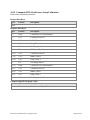
10. DEVICE-SPECIFIC COMMANDS
The following device-specific commands are implemented:
203
Read Transmitter Information
204
Read Transmitter Alarm Parameters
205
Set Transmitter Alarm Parameters
206
Read Transmitter Date & Time
207
Set Transmitter Date & Time
208
Read Transmitter Editor Parameters
209
Set Transmitter Editor Parameters
210
Read Sensor Information General
211
Read Sensor Information Detailed
212
Read Sensor Information Dates
213
Read Sensor Information Live
214
Backup/Restore Transmitter Parameters
220
Read Sensor Setup General
221
Set Sensor Setup General
222
Read Sensor Setup Calibration
223
Set Sensor Setup Calibration
224
Read Sensor Setup Alarms
225
Set Sensor Setup Alarms
226
Read Sensor Names
227
Set Sensor Names
228
Read Sensor Calibration Information
229
Zero & Span Sensors
230
Set System Inhibit
231
Alarm Acknowledge
232
Read Sensor Offline Parameters
233
Set Sensor Offline
234
Read Loop Trim Parameters
235
Set Loop Trim Parameters
Revision 1.0, Release Date: 30 August, 2013
Page 10 of 47
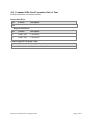
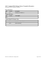
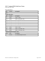
10.1 Command #203: Read Transmitter Information
Read the transmitters basic information.
Request Data Bytes
Byte
Format
Description
None
Response Data Bytes
Byte
Format
Description
0-15
String
TX Name
16-29
String
TX Serial Number
30-37
String
TX Model Number
38-41
String
TX Code Version
42-44
HART date
Current Date
45-48
HART time
Current Time
Command-Specific Response Codes
Code
Class
Description
0
Success
No Command-Specific Errors
Revision 1.0, Release Date: 30 August, 2013
Page 11 of 47
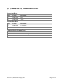
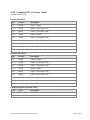
10.2 Command #204: Read Transmitter Alarm Parameters
Read the transmitter alarm parameters.
Request Data Bytes
Byte
Format
Description
None
Response Data Bytes
Byte
Format
Description
0
U8
Alarm logic 1
1-2
U16
Alarm off time delay 1
3
U8
Alarm logic 2
4-5
U16
Alarm off time delay 2
6
U8
Alarm logic 3
7-8
U16
Alarm off time delay 3
Command-Specific Response Codes
Code
Class
Description
0
Success
No Command-Specific Errors
Revision 1.0, Release Date: 30 August, 2013
Page 12 of 47
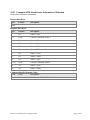
10.3 Command #205: Set Transmitter Alarm Parameters
Write the transmitter alarm parameters.
Request Data Bytes
Byte
Format
Description
0
U8
Alarm logic 1
1-2
U16
Alarm off time delay 1
3
U8
Alarm logic 2
4-5
U16
Alarm off time delay 2
6
U8
Alarm logic 3
7-8
U16
Alarm off time delay 3
Response Data Bytes
Byte
Format
Description
0
U8
Alarm 1 logic
1-2
U16
Alarm 1 off time delay
3
U8
Alarm 2 logic
4-5
U16
Alarm 2 off time delay
6
U8
Alarm 3 logic
7-8
U16
Alarm 3 off time delay
Command-Specific Response Codes
Code
Class
Description
0
5
Success
Error
No Command-Specific Errors
Too few data bytes
Revision 1.0, Release Date: 30 August, 2013
Page 13 of 47
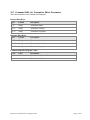
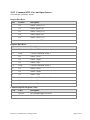
10.4 Command #206: Read Transmitter Date & Time
Read the transmitters current date and time.
Request Data Bytes
Byte
Format
Description
None
Response Data Bytes
Byte
Format
Description
0-2
HART date
Current date
3-6
HART time
Current time
Command-Specific Response Codes
Code
Class
Description
0
Success
No Command-Specific Errors
Revision 1.0, Release Date: 30 August, 2013
Page 14 of 47
10.5 Command #207: Set Transmitter Date & Time
Write the transmitters date and time.
Request Data Bytes
Byte
Format
Description
0-2
HART date
Date
3-6
HART time
Time
Response Data Bytes
Byte
Format
Description
0-2
HART date
Current date
3-6
HART time
Current time
Command-Specific Response Codes
Code
Class
Description
0
5
Success
Error
No Command-Specific Errors
Too few data bytes
Revision 1.0, Release Date: 30 August, 2013
Page 15 of 47
10.6 Command #208: Read Transmitter Editor Parameters
Read the transmitter name, latitude and longitude.
Request Data Bytes
Byte
Format
Description
None
Response Data Bytes
Byte
Format
Description
0-15
String
Transmitter name
16-25
String
Transmitter latitude
26-35
String
Transmitter longitude
Command-Specific Response Codes
Code
Class
Description
0
Success
No Command-Specific Errors
Revision 1.0, Release Date: 30 August, 2013
Page 16 of 47
10.7 Command #209: Set Transmitter Editor Parameters
Write the transmitter name, latitude and longitude.
Request Data Bytes
Byte
Format
Description
0-15
String
Transmitter name
16-25
String
Transmitter latitude
26-35
String
Transmitter longitude
Response Data Bytes
Byte
Format
Description
0-15
String
Transmitter name
16-25
String
Transmitter latitude
26-35
String
Transmitter longitude
Command-Specific Response Codes
Code
Class
Description
0
5
Success
Error
No Command-Specific Errors
Too few data bytes
Revision 1.0, Release Date: 30 August, 2013
Page 17 of 47
10.8 Command #210: Read Sensor Information General
Read sensor general information.
Request Data Bytes
Byte
Format
Description
None
Response Data Bytes
Byte
Format
Description
0-13
String
Sensor 1 serial number
14
U8
Gas type 1
15
U8
Gas units 1
16-23
String
Sensor 1 model number
24-37
String
Sensor 2 serial number
38
U8
Gas type 2
39
U8
Gas units 2
40-47
String
Sensor 2 model number
48-61
String
Sensor 3 serial number
62
U8
Gas type 3
63
U8
Gas units 3
64-71
String
Sensor 3 model number
Command-Specific Response Codes
Code
Class
Description
0
Success
No Command-Specific Errors
Revision 1.0, Release Date: 30 August, 2013
Page 18 of 47
10.9 Command #211: Read Sensor Information Detailed
Read sensor detailed information.
Request Data Bytes
Byte
Format
Description
None
Response Data Bytes
Byte
Format
Description
0-3
Float
Current Cal Factor 1
4-7
Float
Current Cal Temperature 1
8-9
U16
Zero Offset 1
10
U8
Sensor Life 1
11
U8
Cal Required 1
12-15
Float
Current Cal Factor 2
16-19
Float
Current Cal Temperature 2
20-21
U16
Zero Offset 2
22
U8
Sensor Life 2
23
U8
Cal Required 2
24-27
Float
Current Cal Factor 3
28-31
Float
Current Cal Temperature 3
32-33
U16
Zero Offset 3
34
U8
Sensor Life 3
35
U8
Cal Required 3
Command-Specific Response Codes
Code
Class
Description
0
Success
No Command-Specific Errors
Revision 1.0, Release Date: 30 August, 2013
Page 19 of 47
10.10 Command #212: Read Sensor Information Dates
Read sensor calibration dates.
Request Data Bytes
Byte
Format
Description
None
Response Data Bytes
Byte
Format
Description
0-2
HART date
Mfg Cal date 1
3-5
HART date
Install Cal Date 1
6-8
HART date
Prior Cal Date 1
9-11
HART date
Current Cal Date 1
12-14
HART date
Mfg Cal date 2
15-17
HART date
Install Cal Date 2
18-20
HART date
Prior Cal Date 2
21-23
HART date
Current Cal Date 2
24-26
HART date
Mfg Cal date 3
27-29
HART date
Install Cal Date 3
30-32
HART date
Prior Cal Date 3
33-35
HART date
Current Cal Date 3
Command-Specific Response Codes
Code
Class
Description
0
Success
No Command-Specific Errors
Revision 1.0, Release Date: 30 August, 2013
Page 20 of 47
10.11 Command #213: Read Sensor Information Live
Read sensor live information.
Request Data Bytes
Byte
Format
Description
None
Response Data Bytes
Byte
Format
Description
0-3
Float
Gas Concentration 1
4-5
U16
Voltage 1
6-9
Float
Temperature 1
10-11
U16
Gas A-D 1
12-15
Float
Gas Concentration 2
16-17
U16
Voltage 2
18-21
Float
Temperature 2
22-23
U16
Gas A-D 2
24-27
Float
Gas Concentration 3
28-29
U16
Voltage 3
30-33
Float
Temperature 3
34-35
U16
Gas A-D 3
Command-Specific Response Codes
Code
Class
Description
0
Success
No Command-Specific Errors
Revision 1.0, Release Date: 30 August, 2013
Page 21 of 47
10.12 Command #214: Backup / Restore Transmitter Parameters
Backup and restore transmitter parameters.
Request Data Bytes
Byte
Format
0
U8
Response Data Bytes
Byte
Format
Description
Backup (0) or Restore (1)
Description
None
Command-Specific Response Codes
Code
Class
Description
0
2
5
Success
Error
Error
No Command-Specific Errors
Invalid Selection
Too Few Data Bytes
Revision 1.0, Release Date: 30 August, 2013
Page 22 of 47
10.13 Command #220: Read Sensor Setup General
Read sensor general setup parameters.
Request Data Bytes
Byte
Format
Description
None
Response Data Bytes
Byte
Format
Description
0
U8
Gas Range Index 1
1-4
Float
Deadband 1
5-6
U16
Sensor Warmup Time 1
7
U8
Display Negative 1
8
U8
Gas Type 1
9
U8
Gas Units 1
10
U8
Gas Range Index 2
11-14
Float
Deadband 2
15-16
U16
Sensor Warmup Time 2
17
U8
Display Negative 2
18
U8
Gas Type 2
19
U8
Gas Units 2
20
U8
Gas Range Index 3
21-24
Float
Deadband 3
25-26
U16
Sensor Warmup Time 3
27
U8
Display Negative 3
28
U8
Gas Type 3
29
U8
Gas Units 3
Command-Specific Response Codes
Code
Class
Description
0
Success
No Command-Specific Errors
Revision 1.0, Release Date: 30 August, 2013
Page 23 of 47
10.14 Command #221: Set Sensor Setup General
Set sensor general setup parameters.
Request Data Bytes
Byte
Format
Description
0
U8
Gas Range Index 1
1-4
Float
Deadband 1
5-6
U16
Sensor Warmup Time 1
7
U8
Display Negative 1
8
U8
Gas Type 1
9
U8
Gas Units 1
10
U8
Gas Range Index 2
11-14
Float
Deadband 2
15-16
U16
Sensor Warmup Time 2
17
U8
Display Negative 2
18
U8
Gas Type 2
19
U8
Gas Units 2
20
U8
Gas Range Index 3
21-24
Float
Deadband 3
25-26
U16
Sensor Warmup Time 3
27
U8
Display Negative 3
28
U8
Gas Type 3
29
U8
Gas Units 3
Response Data Bytes
Byte
Format
Description
0
U8
Gas Range Index 1
1-4
Float
Deadband 1
5-6
U16
Sensor Warmup Time 1
7
U8
Display Negative 1
8
U8
Gas Type 1
9
U8
Gas Units 1
10
U8
Gas Range Index 2
Revision 1.0, Release Date: 30 August, 2013
Page 24 of 47
11-14
Float
Deadband 2
15-16
U16
Sensor Warmup Time 2
17
U8
Display Negative 2
18
U8
Gas Type 2
19
U8
Gas Units 2
20
U8
Gas Range Index 3
21-24
Float
Deadband 3
25-26
U16
Sensor Warmup Time 3
27
U8
Display Negative 3
28
U8
Gas Type 3
29
U8
Gas Units 3
Command-Specific Response Codes
Code
Class
Description
0
Success
No Command-Specific Errors
5
Error
Too Few Data Bytes
Revision 1.0, Release Date: 30 August, 2013
Page 25 of 47
10.15 Command #222: Read Sensor Setup Calibration
Read sensor calibration parameters.
Request Data Bytes
Byte
Format
Description
None
Response Data Bytes
Byte
Format
Description
0-3
Float
Calibration Gas Concentration 1
4-5
U16
Calibration Period 1
6-7
U16
Inhibit Timer 1
8-9
U16
Purge Timer 1
10
U8
Gas Range Index 1
11-14
Float
Calibration Gas Concentration 2
15-16
U16
Calibration Period 2
17-18
U16
Inhibit Timer 2
19-20
U16
Purge Timer 2
21
U8
Gas Range Index 2
22-25
Float
Calibration Gas Concentration 3
26-27
U16
Calibration Period 3
28-29
U16
Inhibit Timer 3
30-31
U16
Purge Timer 3
32
U8
Gas Range Index 3
Command-Specific Response Codes
Code
Class
Description
0
Success
No Command-Specific Errors
Revision 1.0, Release Date: 30 August, 2013
Page 26 of 47
10.16 Command #223: Set Sensor Setup Calibration
Set sensor calibration parameters.
Request Data Bytes
Byte
Format
Description
0-3
Float
Calibration Gas Concentration 1
4-5
U16
Calibration Period 1
6-7
U16
Inhibit Timer 1
8-9
U16
Purge Timer 1
10
U8
Gas Range Index 1
11-14
Float
Calibration Gas Concentration 2
15-16
U16
Calibration Period 2
17-18
U16
Inhibit Timer 2
19-20
U16
Purge Timer 2
21
U8
Gas Range Index 2
22-25
Float
Calibration Gas Concentration 3
26-27
U16
Calibration Period 3
28-29
U16
Inhibit Timer 3
30-31
U16
Purge Timer 3
32
U8
Gas Range Index 3
Response Data Bytes
Byte
Format
Description
0-3
Float
Calibration Gas Concentration 1
4-5
U16
Calibration Period 1
6-7
U16
Inhibit Timer 1
8-9
U16
Purge Timer 1
10
U8
Gas Range Index 1
11-14
Float
Calibration Gas Concentration 2
15-16
U16
Calibration Period 2
17-18
U16
Inhibit Timer 2
19-20
U16
Purge Timer 2
21
U8
Gas Range Index 2
Revision 1.0, Release Date: 30 August, 2013
Page 27 of 47
22-25
Float
Calibration Gas Concentration 3
26-27
U16
Calibration Period 3
28-29
U16
Inhibit Timer 3
30-31
U16
Purge Timer 3
32
U8
Gas Range Index 3
Command-Specific Response Codes
Code
Class
Description
0
Success
No Command-Specific Errors
5
Error
Too Few Data Bytes
Revision 1.0, Release Date: 30 August, 2013
Page 28 of 47
10.17 Command #224: Read Sensor Setup Alarms
Read sensor alarms set and reset parameters.
Request Data Bytes
Byte
Format
Description
None
Response Data Bytes
Byte
Format
Description
0-3
Float
Alarm 1 Set Point 1
4-7
Float
Alarm 1 Reset Point 1
8-11
Float
Alarm 2 Set Point 1
12-15
Float
Alarm 2 Reset Point 1
16-19
Float
Alarm 3 Set Point 1
20-23
Float
Alarm 3 Reset Point 1
24-27
Float
Alarm 1 Set Point 2
28-31
Float
Alarm 1 Reset Point 2
32-35
Float
Alarm 2 Set Point 2
36-39
Float
Alarm 2 Reset Point 2
40-43
Float
Alarm 3 Set Point 2
44-47
Float
Alarm 3 Reset Point 2
48-51
Float
Alarm 1 Set Point 3
52-55
Float
Alarm 1 Reset Point 3
56-59
Float
Alarm 2 Set Point 3
60-63
Float
Alarm 2 Reset Point 3
Float
Alarm 3 Set Point 3
Float
Alarm 3 Reset Point 3
64-67
68-71
Command-Specific Response Codes
Code
Class
Description
0
Success
No Command-Specific Errors
Revision 1.0, Release Date: 30 August, 2013
Page 29 of 47
10.18 Command #225: Set Sensor Setup Alarms
Set sensor alarms set and reset parameters.
Request Data Bytes
Byte
Format
Description
0-3
Float
Alarm 1 Set Point 1
4-7
Float
Alarm 1 Reset Point 1
8-11
Float
Alarm 2 Set Point 1
12-15
Float
Alarm 2 Reset Point 1
16-19
Float
Alarm 3 Set Point 1
20-23
Float
Alarm 3 Reset Point 1
24-27
Float
Alarm 1 Set Point 2
28-31
Float
Alarm 1 Reset Point 2
32-35
Float
Alarm 2 Set Point 2
36-39
Float
Alarm 2 Reset Point 2
40-43
Float
Alarm 3 Set Point 2
44-47
Float
Alarm 3 Reset Point 2
48-51
Float
Alarm 1 Set Point 3
52-55
Float
Alarm 1 Reset Point 3
56-59
Float
Alarm 2 Set Point 3
60-63
Float
Alarm 2 Reset Point 3
64-67
Float
Alarm 3 Set Point 3
68-71
Float
Alarm 3 Reset Point 3
Response Data Bytes
Byte
Format
Description
0-3
Float
Alarm 1 Set Point 1
4-7
Float
Alarm 1 Reset Point 1
8-11
Float
Alarm 2 Set Point 1
12-15
Float
Alarm 2 Reset Point 1
16-19
Float
Alarm 3 Set Point 1
20-23
Float
Alarm 3 Reset Point 1
24-27
Float
Alarm 1 Set Point 2
Revision 1.0, Release Date: 30 August, 2013
Page 30 of 47
28-31
Float
Alarm 1 Reset Point 2
32-35
Float
Alarm 2 Set Point 2
36-39
Float
Alarm 2 Reset Point 2
40-43
Float
Alarm 3 Set Point 2
44-47
Float
Alarm 3 Reset Point 2
48-51
Float
Alarm 1 Set Point 3
52-55
Float
Alarm 1 Reset Point 3
56-59
Float
Alarm 2 Set Point 3
60-63
Float
Alarm 2 Reset Point 3
64-67
Float
Alarm 3 Set Point 3
68-71
Float
Alarm 3 Reset Point 3
Command-Specific Response Codes
Code
Class
Description
0
Success
No Command-Specific Errors
5
Error
Too Few Data Bytes
Revision 1.0, Release Date: 30 August, 2013
Page 31 of 47
10.19 Command #226: Read Sensor Names
Read sensor name fields.
Request Data Bytes
Byte
Format
Description
None
Response Data Bytes
Byte
Format
Description
0-15
String
Sensor 1 Name
16-23
String
Sensor 1 Gas Name Line 1
24-31
String
Sensor 1 Gas Name Line 2
32-47
String
Sensor 2 Name
48-55
String
Sensor 2 Gas Name Line 1
56-63
String
Sensor 2 Gas Name Line 2
64-79
String
Sensor 3 Name
80-87
String
Sensor 3 Gas Name Line 1
88-95
String
Sensor 3 Gas Name Line 2
Command-Specific Response Codes
Code
Class
Description
0
Success
No Command-Specific Errors
Revision 1.0, Release Date: 30 August, 2013
Page 32 of 47
10.20 Command #227: Set Sensor Names
Set sensor name fields.
Request Data Bytes
Byte
Format
Description
0-15
String
Sensor 1 Name
16-23
String
Sensor 1 Gas Name Line 1
24-31
String
Sensor 1 Gas Name Line 2
32-47
String
Sensor 2 Name
48-55
String
Sensor 2 Gas Name Line 1
56-63
String
Sensor 2 Gas Name Line 2
64-79
String
Sensor 3 Name
80-87
String
Sensor 3 Gas Name Line 1
88-95
String
Sensor 3 Gas Name Line 2
Response Data Bytes
Byte
Format
Description
0-15
String
Sensor 1 Name
16-23
String
Sensor 1 Gas Name Line 1
24-31
String
Sensor 1 Gas Name Line 2
32-47
String
Sensor 2 Name
48-55
String
Sensor 2 Gas Name Line 1
56-63
String
Sensor 2 Gas Name Line 2
64-79
String
Sensor 3 Name
80-87
String
Sensor 3 Gas Name Line 1
88-95
String
Sensor 3 Gas Name Line 2
Command-Specific Response Codes
Code
Class
Description
0
Success
No Command-Specific Errors
5
Error
Too Few Data Bytes
Revision 1.0, Release Date: 30 August, 2013
Page 33 of 47
10.21 Command #228: Read Sensor Information Calibration
Read sensor calibration information.
Request Data Bytes
Byte
Format
Description
None
Response Data Bytes
Byte
Format
Description
0
U8
Sensor 1 Life
1-4
Float
Current Calibration Factor 1
5
U8
Sensor 1 Zero
6
U8
Sensor 1 Span
7
U8
Sensor 2 Life
8-11
Float
Current Calibration Factor 2
12
U8
Sensor 2 Zero
13
U8
Sensor 2 Span
14
U8
Sensor 3 Life
15-18
Float
Current Calibration Factor 3
19
U8
Sensor 3 Zero
20
U8
Sensor 3 Span
Command-Specific Response Codes
Code
Class
Description
0
Success
No Command-Specific Errors
Revision 1.0, Release Date: 30 August, 2013
Page 34 of 47
10.22 Command #229: Zero and Span Sensors
Zero and span (calibrate) sensors.
Request Data Bytes
Byte
Format
Description
0
U8
Sensor 1 zero (T/F)
1
U8
Sensor 1span (T/F)
2
U8
Sensor 2 zero (T/F)
3
U8
Sensor 2span (T/F)
4
U8
Sensor 3 zero (T/F)
5
U8
Sensor 4span (T/F)
Response Data Bytes
Byte
Format
Description
0
U8
Sensor 1 Life
1-4
Float
Current Calibration Factor 1
5
U8
Sensor 1 Zero
6
U8
Sensor 1 Span
7
U8
Sensor 2 Life
8-11
Float
Current Calibration Factor 2
12
U8
Sensor 2 Zero
13
U8
Sensor 2 Span
14
U8
Sensor 3 Life
15-18
Float
Current Calibration Factor 3
19
U8
Sensor 3 Zero
20
U8
Sensor 3 Span
Command-Specific Response Codes
Code
Class
Description
0
Success
No Command-Specific Errors
5
Error
Too Few Data Bytes
Revision 1.0, Release Date: 30 August, 2013
Page 35 of 47
10.23 Command #230: Set System Inhibit
Put the transmitter into System Inhibit.
Request Data Bytes
Byte
Format
0
U8
Response Data Bytes
Byte
Format
Description
Enable Inhibit (1) or Disable Inhibit (0)
Description
None
Command-Specific Response Codes
Code
Class
Description
0
Success
No Command-Specific Errors
2
Error
Invalid Selection
5
Error
Too Few Data Bytes
Revision 1.0, Release Date: 30 August, 2013
Page 36 of 47
10.24 Command #231: Alarm Acknowledge
Alarm acknowledge.
Request Data Bytes
Byte
Format
Description
None
Response Data Bytes
Byte
Format
Description
None
Command-Specific Response Codes
Code
Class
Description
0
Success
No Command-Specific Errors
Revision 1.0, Release Date: 30 August, 2013
Page 37 of 47
10.25 Command #230: Read Sensor Offline Settings
Read sensor online/offline status.
Request Data Bytes
Byte
Format
Description
None
Response Data Bytes
Byte
Format
0
Bits
Description
bit 3: Sensor 1 - (1) online (0) offline
bit 4: Sensor 2 - (1) online (0) offline
bit 5: Sensor 3 - (1) online (0) offline
Command-Specific Response Codes
Code
Class
Description
0
Success
No Command-Specific Errors
Revision 1.0, Release Date: 30 August, 2013
Page 38 of 47
10.26 Command #231: Set Sensor Offline
Set sensor offline.
Request Data Bytes
Byte
Format
Description
None
Response Data Bytes
Byte
Format
0
Bits
Description
bit 3: Sensor 1 - (0)set sensor offline
bit 4: Sensor 2 - (0)set sensor offline
bit 5: Sensor 3 - (0)set sensor offline
Command-Specific Response Codes
Code
Class
Description
0
Success
No Command-Specific Errors
5
Error
Too Few Data Bytes
Revision 1.0, Release Date: 30 August, 2013
Page 39 of 47
10.27 Command #234: Read Loop Trim Parameters
Read sensor online/offline status.
Request Data Bytes
Byte
Format
Description
None
Response Data Bytes
Byte
Format
Description
0
S8
Current Loop 1: 4mA offset
1
S8
Current Loop 1: 20mA offset
2
S8
Current Loop 2: 4mA offset
3
S8
Current Loop 2: 20mA offset
4
S8
Current Loop 3: 4mA offset
5
S8
Current Loop 4: 20mA offset
Command-Specific Response Codes
Code
Class
Description
0
Success
No Command-Specific Errors
Revision 1.0, Release Date: 30 August, 2013
Page 40 of 47
10.28 Command #235: Set Loop Trim Parameters
Read sensor online/offline status.
Request Data Bytes
Byte
Format
Description
0
S8
Current Loop 1: 4mA offset
1
S8
Current Loop 1: 20mA offset
2
S8
Current Loop 2: 4mA offset
3
S8
Current Loop 2: 20mA offset
4
S8
Current Loop 3: 4mA offset
5
S8
Current Loop 4: 20mA offset
Response Data Bytes
Byte
Format
Description
0
S8
Current Loop 1: 4mA offset
1
S8
Current Loop 1: 20mA offset
2
S8
Current Loop 2: 4mA offset
3
S8
Current Loop 2: 20mA offset
4
S8
Current Loop 3: 4mA offset
5
S8
Current Loop 4: 20mA offset
Command-Specific Response Codes
Code
Class
Description
0
Success
No Command-Specific Errors
5
Error
Too Few Data Bytes
Revision 1.0, Release Date: 30 August, 2013
Page 41 of 47
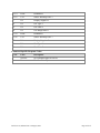
11. PERFORMANCE
11.1 Sampling Rates
The PV, SV and TV are updated every 2 seconds.
11.2 Power-Up
On power up the transmitter will go through an initialization sequence which takes
approximately 15 seconds. During this time the device will not respond to HART commands
and the analog output will be set to the Inhibit level. The analog output will stay in Inhibit level
until sensor 1 has completed its warm-up time or if a fault occurs. If a fault occurs the output
will switch to the fault level. If no fault occurs the analog output will switch to active signaling
mode.
11.3 Reset
Command 42 ("Device Reset") causes the device to reset its microprocessor. The resulting
restart is identical to the normal power up sequence.
11.4 Self-Test
Command 41 is not supported in the HART interface.
Self-test is executed during the device initialization at power up and following Command 42
("Device Reset"). The self-test includes:
Microprocessor
Oscillator drift
Transmitter input voltage
Sensor communications
RAM
Program ROM
Configuration storage EEPROM
During device initialization at power-up or reset, the analog output is set to Inhibit level and the
device will not respond to HART commands.
Continuous self-testing is also part of the normal device operation. The same checks are made,
but have no impact on HART communications.
Revision 1.0, Release Date: 30 August, 2013
Page 42 of 47
11.5 Command Response Times
Minimum
20ms
Typical
50ms
Maximum
100mS
Revision 1.0, Release Date: 30 August, 2013
Page 43 of 47
11.6 Busy and Delayed-Response
The transmitter may respond with "busy" status if a further command is received while self-test
is underway.
Delayed-response is not used.
11.7 Long Messages
The largest data field used is in the response to Command 226: 98 bytes including the two status
bytes.
11.8 Non-Volatile Memory
EEPROM is used to hold the device’s configuration parameters. New data is written to this
memory immediately on execution of a write command.
11.9 Modes
Fixed current mode is implemented, using Command 40. This mode is cleared by power loss or
reset.
11.10 Write Protection
Not implemented.
11.11 Damping
No additional damping is provided beyond the sampling of the sensor.
Revision 1.0, Release Date: 30 August, 2013
Page 44 of 47
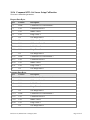
ANNEX A.
CAPABILITY CHECKLIST
Manufacturer, model and revision
Scott Safety, Meridian Rev1.0
Device type
Transmitter
HART revision
7.5
Device Description available
Yes
Number of sensors
Up to 3
Number and type of host side signals
1: 4 - 20mA analog
Number of Device Variables
0
Number of Dynamic Variables
3
Mappable Dynamic Variables
No
Number of common-practice commands
17
Number of device-specific commands
2
Bits of additional device status
8
Alternative operating modes
No
Burst mode
No
Write-protection
No
Revision 1.0, Release Date: 30 August, 2013
Page 45 of 47
ANNEX B. DEFAULT CONFIGURATION
Parameter
Default value
Lower Range Value
0
Upper Range Value
Sensor specific
Number of response preambles
5
Revision 1.0, Release Date: 30 August, 2013
Page 46 of 47
ANNEX C.
A1.
REVISION HISTORY
Rev 1.0 Initial release
Revision 1.0, Release Date: 30 August, 2013
Page 47 of 47