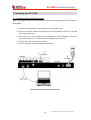
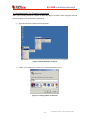
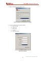
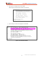
1
EU-200B
Installation Manual
PLC EMS Unit
Plug into the future
Powerline Communication by Xeline
Xeline Co., Ltd.
EU-200B Installation Manual
ATTENTION
This equipment conforms with the following standard(s):
(1) EN55022
(2) EN60950-1
2
This document is subject to change without prior notice.
EU-200B Installation Manual
Table of Contents
1. Introduction ······························································································· 5
2. Before Installing the EU-200B ·········································································· 6
2.1 Package Contents ························································································································ 6
2.2 Prerequisites································································································································· 6
2.3 Safety Precautions······················································································································· 7
3. Getting to Know the EU-200B ·········································································· 8
3.1 Front View ···································································································································· 8
3.2 Rear View······································································································································ 8
3.3 Product Specifications················································································································· 9
4. Installing the EU-200B ·················································································· 10
4.1 Connecting the LAN and Console····························································································· 10
4.2 Configuring PC for Console Connection ·················································································· 11
4.3 Setting the IP of the EU-200B ·································································································· 13
5. Trouble Shooting························································································· 15
6. Appendix ·································································································· 16
3
This document is subject to change without prior notice.
EU-200B Installation Manual
Figure Index
Figure 1 PLC EMS System Configuration..................................................................... 5
Figure 2 EU-200B Package Contents .......................................................................... 6
Figure 3 EU-200B Front View..................................................................................... 8
Figure 4 EU-200B Rear View ...................................................................................... 8
Figure 5 Connecting the LAN and Console ............................................................... 10
Figure 6 Microsoft Hyper Terminal .......................................................................... 11
Figure 7 Creating a New Connection ....................................................................... 11
Figure 8 Assigning a Communication Port Number ................................................... 12
Figure 9 Port Settings ............................................................................................. 12
Figure 10 Login Prompt Window.............................................................................. 13
Figure 11 EU-200B Login ......................................................................................... 13
Figure 12 IP Configuration Example......................................................................... 14
Figure 13 IP Confirmation Example ......................................................................... 14
4
This document is subject to change without prior notice.
EU-200B Installation Manual
1. Introduction
Powerline Communication (PLC) technology uses the existing powerline infrastructure to
transfer high-speed data, eliminating the need for expensive and complicated cable
installation. Because the home or office is already a ‘wired network’ through powerlines,
Xeline’s PLC system offers a cost-effective and easy-to-install Internet access solution from
any electrical outlet.
Xeline’s EU-200B is the EMS (Element Management System) Unit that enables the remote
monitoring and management of the XPAS-200B PLC system by providing information on the
status of the PLC sites.
The EU-200B monitors and manages network information that is characteristic only to PLC,
such as bit loading, powerline channel information, and etc., to ensure reliable network
performance.
Remote configuration and firmware upgrade are also supported through the EU-200B for
efficient setup and maintenance of the PLC units in mass-usage environments.
EMS Unit
Figure 1 PLC EMS System Configuration
5
This document is subject to change without prior notice.
EU-200B Installation Manual
2. Before Installing the EU-200B
2.1 Package Contents
Before installing, first verify that you have all of the following items.
○EU-200B EMS Unit
○1 RJ-45 Cable (Direct)
○ 1 Console Cable (RJ-45 / RS-232)
○ 1 Power Cable
○ 1 Installation manual
Figure 2 EU-200B Package Contents
If there is a missing item or any visible damage, notify your service provider or dealer
immediately.
2.2 Prerequisites
In order to install the EU-200B, you will need the following items:
(1) Power supply for the EU-200B
(2) Convenient access to the local backbone network
(3) Sufficient space to install the EU-200B
(4) 1 Laptop PC
(5) 1 Switch Hub (10base-T or higher)
(6) 1 Metal Cabinet [Recommended]
6
This document is subject to change without prior notice.
EU-200B Installation Manual
2.3 Safety Precautions
Please make sure to read the following guidelines before installation.
(1) Read all instructions before installing or operating the equipment. Be sure to
keep this manual for further reference.
(2) Please follow all the safety precautions and other installation procedures.
(3) Do not use this equipment near heaters or other devices that emit high heat.
(4) Do not place heavy objects on top of the EU-200B.
(5) Install the EU-200B near the ISP backbone or Switch Hub. Prepare a protective
metal case to house the EU-200B, backbone equipment, and Switch Hub.
(6) Avoid the following environments:
- Areas with extremely high or low temperatures
- Areas with high humidity or high risk of flooding
- Areas where sudden changes in temperature occur
- Under direct sunlight
(In outdoor configurations, install the EU-200B in a shady area away from
direct sunlight.)
7
This document is subject to change without prior notice.
EU-200B Installation Manual
3. Getting to Know the EU-200B
3.1 Front View
Figure 3 EU-200B Front View
POWER
CONSOLE
EMS
Activates when power is turned on.
TX
Blinks during console data transmission from the EU-200B to the PC.
RX
Blinks during console data transmission from the PC to the EU-200B.
LNK
Activates when the EU-200B is connected to the network.
ACT
Blinks when EMS data is transmitted/received.
ALM
Activates when the EU-200B is in abnormal operation.
3.2 Rear View
Figure 4 EU-200B Rear View
CONSOLE
Console port used to connect the EU-200B to the PC (RJ-45 / RS-232)
LAN
RJ-45 Ethernet port for connection to the Switch Hub
Power Switch
Switch for turning power ON/OFF.
AC Inlet
For connection to the power cable.
8
This document is subject to change without prior notice.
EU-200B Installation Manual
3.3 Product Specifications
Category
Specifications
Main Processor
MPC850-50MHz
Memory
32MB DRAM
Flash Memory
4MB
Boot Rom
512KB
EEPROM
2kbit [IIC Bus]
Serial Port
RS232 [1 port]
LAN Port
10 Base – TX [1 port]
Power
External Power : AC 110V - 240V, 0.4A, 50/60Hz
Dimensions
320 x 200 x 44mm (W x D x H)
Weight
1.75Kg
9
This document is subject to change without prior notice.
EU-200B Installation Manual
4. Installing the EU-200B
4.1 Connecting the LAN and Console
Note: The EU-200B should be located within the same broadcasting domain as the Stations to
be managed.
① Connect the ISP backbone to the UPLINK port of the Switch Hub.
② Insert a RJ-45 direct cable into the LAN port of the EU-200B and connect to the LAN
port of the Switch Hub.
③ Insert the RJ-45 / RS-232 cable into the CONSOLE port of the EU-200B. Connect the
other end of the RJ-45 / RS-232 cable into the SERIAL port of the PC.
④ Connect the power cable to the EU-200B.
⑤ Turn on the power of the EU-200B and Switch Hub.
Figure 5 Connecting the LAN and Console
10
This document is subject to change without prior notice.
EU-200B Installation Manual
4.2 Configuring PC for Console Connection
Note: The following example is based on Microsoft Hyper Terminal. Other programs may be
used according to the technician’s preference.
①
Open the Microsoft Hyper Terminal program.
Figure 6 Microsoft Hyper Terminal
② Create a new connection. Enter a new name and select an icon.
Figure 7 Creating a New Connection
11
This document is subject to change without prior notice.
EU-200B Installation Manual
③ Assign a communication port number to use.
Figure 8 Assigning a Communication Port Number
④ Set the port settings as the following example:
A.
Baud rate: 9600
B.
Data bits: 8
C.
Parity: None
D.
Stop bits: 1
E.
Flow control: None
Figure 9 Port Settings
12
This document is subject to change without prior notice.
EU-200B Installation Manual
⑤ Turn on the power of the EU-200B.
⑥ The following login prompt will appear in the Hyper Terminal window.
Figure 10 Login Prompt Window
4.3 Setting the IP of the EU-200B
①
Use the following id and password to log into the EU-200B.
Login ID: root
Password: xeline
Figure 11 EU-200B Login
13
This document is subject to change without prior notice.
EU-200B Installation Manual
②
Type <ipset> to configure the IP of the EU-200B.
Note: Always use a fixed IP address. DHCP is not supported!
Figure 12 IP Configuration Example
③
Type <ifconfig> to confirm the changed IP of the EU-200B.
④
Figure 13 IP Confirmation Example
14
This document is subject to change without prior notice.
EU-200B Installation Manual
5. Trouble Shooting
Console
Problem
Checklist
The POWER LED does
Check if the power cable is firmly plugged into the EU-200B and
not activate.
power outlet.
No information is
① Check if the RJ-45 / RS-232 cable is firmly plugged into the
displayed during
console connection.
EU-200B and PC.
② Check if the selected serial port of the Hyper Terminal
matches the actual serial port.
③ Check if the configured information such as baud rates, data
bits, parity, etc. is correct.
Booting
Problem
Checklist
The login screen does
Check if the ALM LED is activated.
not appear.
IP Setting
Problem
IP address is not
configured on EU-200B
Checklist
Check for typos when configuring the IP.
If the problem is still not solved, please contact Xeline’s Technical Support Center.
15
This document is subject to change without prior notice.
EU-200B Installation Manual
6. Appendix
z Copyright 2005 Xeline Co., Ltd. All rights reserved.
All Xeline brand product names are trademarks of Xeline Co., Ltd.
Other product and company names mentioned herein are the trademarks of their
respective owners.
z Information in this document is subject to change without notice. No part of this document
may be reproduced or altered in any form or by any means, electronical or mechanical,
for any purpose, without the express written permission of Xeline Co., Ltd.
z Xeline Technical Support Center
Address: 7F. Chungjin Bldg. 475-22,
Bangbae 2 dong, Seocho-gu,
Seoul 137-819, Republic of Korea
Telephone: +82 2 598 0980
Facsimile: +82 2 598 0975
E-mail: [email protected]
Website: http://www.xeline.com
16
This document is subject to change without prior notice.