1
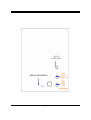
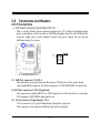
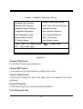
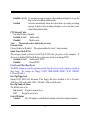
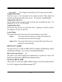
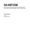
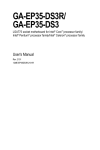
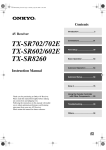
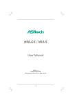
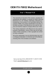
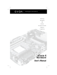
TECHNICAL MANUAL
Of
NVIDIA MCP78S
Based
Mini-ITX M/B For AMD Socket AM2+ Processor
NO.G03-J6C2-F/G03-NC62-F
Rev2.0
Release date:
May, 2008
Trademark:
* Specifications and Information contained in this documentation are furnished for information use only, and are
subject to change at any time without notice, and should not be construed as a commitment by manufacturer.
Environmental Protection Announcement
Do not dispose this electronic device into the trash while discarding. To minimize pollution
and ensure environment protection of mother earth, please recycle.
ii
TABLE OF CONTENT
USER’S NOTICE .................................................................................................................................. iii
MANUAL REVISION INFORMATION ............................................................................................ iii
ITEM CHECKLIST.............................................................................................................................. iii
CHAPTER 1 INTRODUCTION OF AMDCS5536 CHIPSET MOTHERBOARD
1-1
FEATURE OF MOTHERBOARD..................................................................................... 1
1-1-1 SPECICAL FEATURE OF MOTHERBOARD............................................................. 2
1-2 SPECIFICATION.................................................................................................................. 3
1-3 LAYOUT DIAGRAM & JUMPER SETTING ................................................................... 5
CHAPTER 2 HARDWARE INSTALLATION
2-1 HARDWARE INSTALLATION STEPS............................................................................. 8
2-2 CHECKING MOTHERBOARD'S JUMPER SETTING .................................................. 8
2-3 INSTALL MEMORY............................................................................................................ 9
2-4 EXPANSION CARDS ........................................................................................................... 11
2-4-1
PROCEDURE FOR EXPANSION CARD INSTALLATION ............................ 11
2-5 CONNECTORS AND HEADERS ....................................................................................... 12
2-5-1
CONNECTORS....................................................................................................... 12
2-5-2
HEADERS ............................................................................................................... 14
2-6 STARTING UP YOUR COMPUTER ................................................................................. 16
CHAPTER 3
3-1
ENTERING SETUP…………………………………………………………………………18
3-2
GETTING HELP..…………………………………………………………………………...19
3-3
THE MAIN MENU…………………………………………………………………………..19
3-4
ADVANCED BIOS FEATURES.……………………………………………………………22
3-5
INTERGRATED PERIPHERALS…….................................................................................25
3-6
PC HEALTH STATUS……………………………………………………………………25
3-7
POWER USER OVERCLOCK SETTING..……………………………………………..27
iii
USER’S NOTICE
COPYRIGHT OF THIS MANUAL BELONGS TO THE MANUFACTURER. NO PART OF THIS MANUAL,
INCLUDING THE PRODUCTS AND SOFTWARE DESCRIBED IN IT MAY BE REPRODUCED,
TRANSMITTED OR TRANSLATED INTO ANY LANGUAGE IN ANY FORM OR BY ANY MEANS WITHOUT
WRITTEN PERMISSION OF THE MANUFACTURER.
THIS MANUAL CONTAINS ALL INFORMATION REQUIRED TO USE INTEL 945GM CHIPSET
MOTHER-BOARD SERIES AND WE DO ASSURE THIS MANUAL MEETS USER’S REQUIREMENT BUT WILL
CHANGE, CORRECT ANY TIME WITHOUT NOTICE. MANUFACTURER PROVIDES THIS MANUAL “AS IS”
WITHOUT WARRANTY OF ANY KIND, AND WILL NOT BE LIABLE FOR ANY INDIRECT, SPECIAL,
INCIDENTIAL OR CONSEQUENTIAL DAMAGES (INCLUDING DAMANGES FOR LOSS OF PROFIT, LOSS OF
BUSINESS, LOSS OF USE OF DATA, INTERRUPTION OF BUSINESS AND THE LIKE).
PRODUCTS AND CORPORATE NAMES APPEARING IN THIS MANUAL MAY OR MAY NOT BE
REGISTERED TRADEMARKS OR COPYRIGHTS OF THEIR RESPECTIVE COMPANIES, AND THEY ARE
USED ONLY FOR IDENTIFICATION OR EXPLANATION AND TO THE OWNER’S BENEFIT, WITHOUT
INTENT TO INFRINGE.
Manual Revision Information
Reversion
2.0
Revision History
Second Edition
Date
May, 2008
Item Checklist
5
5
5
5
5
5
Motherboard
Cable for IDE Port
CD for motherboard utilities
Motherboard User’s Manual
Back panel(optional)
DVI to HDMI Connector
iv
Chapter 1
Introduction of the Motherboard
1-1
Feature of motherboard
The motherboard series are designed for the new generation AMD processor family
guaranteed both of the performance and stability of general purpose IPC and dedicated IPC
platform solutions. The MCP78S chipset is fully optimized to provide the variety IPC
platform solutions by featuring the high compatibilities and cost-effective, low power
consumption, high performance, and superior core graphics engine.
The motherboard AMD Socket AM2+ Quad core Opteron&Phenom, with low power
consumption never denies high performance. The embedded AMD Socket AM2+ Quad core
Opteron&Phenom family processor has evolved to meet the specific requirements of extended
temperature applications in telecommunications infrastructure (including wired, wireless, and
BSC/MSC), single board computing, automotive and transportation systems and industrial
control and monitoring.
The motherboard series support HT3.0 and DDRII 400/533/667/800 system RAM Modules
which is expandable to 2.0GB. The motherboard offers ULTRA ATA 133 HDD connectors
and Serial ATA2 with RAID 0 ,1, 5,10,JBOD functions which support up to IDE and four
Serial ATA2 devices to accelerate hard disk drives and guarantee the data security without
failure in advanced computing performance. The motherboard provide two Gigabit Ethernet
LAN for internet or intranet connections, one is PCI-E LAN, the other one is PHY LAN
(optional). The motherboard series are also integrated Realtek ALC883 8channel Audio
CODEC on system which is fully compatible with Sound Blaster Pro® that gives you the best
sound quality and compatibility.
Embedded 10 USB2.0 functional ports delivering 480Mb/s data transfer rate, these
motherboards meet USB2.0 demands data transport demands which are also equipped with
1
hardware monitor function on system to monitor and protect your system and maintain your
non-stop business computing.
Targets at High Growth Markets: Digital Home / Digital Office / Digital World
- Personal electronics such as personal video recorders (PVR), set top boxes, home theatres,
digital audio centers, etc.
- Mini PCs / Green clients / Quiet desktop PCs / High density servers
- Home server appliances / Public information/entertainment kiosks / Point-of-Sales
systems / Intelligent displays / Edge networking devices / Hospital monitoring systems /
Municipal control & monitoring systems
1-1.1 Special Feature of motherboard
OC-CON ---(High-polymer Solid Electrolysis Aluminum Capacitors)
The working temperature is from 55 degrees Centigrade below zero to 125 degrees
Centigrade, OC-CON capacitors possess superior physical characteristics that can be while
reducing the working temperature between 20 degrees Centigrade each time, intact extension
10 times of effective product operation lives, at not rising degrees Centigrade of working
temperatures each time a relative one, life of product decline 10% only too.
2
1-2
Specification
Spec
Design
Chipset
Embedded CPU
Memory Socket
x Expansion Slots
Description
∗
∗
∗
∗
∗
∗
∗
Mini ITX form factor 6 layers PCB size: 17.0x17.0cm
NVIDIA MCP78S single chipset
Support HT3.0
Low Power Consumption
Socket AM2+ / AM2 AMD CPU
240-pin DDRII DIMM socket x1
Support DDRII 667MHz /DDRII 800MHz system Modules DDR
memory
∗ Expandable to 2GB.
∗ 32-bit PCI slot x 1pcs
∗
Integrate IDE
LAN
∗
∗
∗
Audio
∗
∗
∗
One PCI IDE controller that supports PCI Bus Mastering, ATA
PIO/DMA and the ULTRA DMA 133/100/66 functions that
deliver the data transfer rate up to 100 MB/s;
Integrated Realtek RTL8111B/C PCI-E LAN.
Integrated Realtek RTL8211B LAN PHY LAN(optional).
Support Fast Ethernet LAN function of providing 10Mb/100Mb
/Gigabit Ethernet data transfer rate
Realtek ALC883 8 channel Audio Codec integrated
Audio driver and utility included
Support SPDIF IN/OUT
3
BIOS
Multi I/O
1-3
∗
∗
∗
∗
∗
∗
∗
Award 8MB SPI Flash ROM
PS/2 keyboard&Mouse Connector
D-Sub 15-pin VGA Conn.
USB 2.0 connector x6, USB2.0 header x2
Serial port D-Sub x2
8-channel Audio connector (Line-out, MIC and SPDIF in/out )
DVI Conn.
Layout Diagram & Jumper Setting
Keyboard
Connector
Line-In / SPDIF in
DVI
Surrback / SPDIF out
Connector
RJ45 LAN(optional)
COM
VGA
Surround
USB
Connector Connector
USB
Connector
Connector
MIC-IN
4
ATX12V Power
AMD Socket AM2+
JP1
Keyboard and USB
Connector
COM Connector
J2
RS232 Power Sel 1
CPU FAN
ATX Power Connector
Clear CMOS
Rs232 Power Sel 2
J3
VGA and DVI
Connector
240pin DDRII
DIMM Socket
Audio
Connector
SYS FAN2
MCP78S Chipset
ATA133
IDE Connector
USB Port Connector
(optional)
SYS FAN1
Front Panel
SATAII (1,2,3,4)
CD IN
Connector
Connector
Speak Connector
Audio
Connector
PCI Slot
5
Power LED
USB Port Connector
(USB1,USB2)
ALC 883
AUDIO CODEC
8MB Flash SPI ROM BIOS
RTL
8111C
PCI-E LAN
RTL
8211B
LAN
PHY(optional)
6
Jumper
Jumper
Name
CMOS RAM Clear Function Setting
Description
3-pin Block
Page
p.9
Name
4-Pin 12V Power Connector
USB Port Connector
RJ45 LAN Connector
VGA Port Connector
Line-Out /MIC Audio Connector
PS2 Keyboard & Mouse Connector
Description
4-pin Block
4-pin Connector
4-pin Connector
15-pin Female
2 Phone Jack
5-PinConnector
Page
p.12
p.13
p.14
p.12
p.13
p.14
Header
USB1,USB2
IDE
Name
USB2.0 Port Headers
44-Pin IDE Connector
Description
9-pin Block
44-pin IDE Block
Page
p.14
p.15
RESET
PWR BTN
SATAII1,2,3,4
Reset switch lead
Power Button Headers
Serial ATA Headers
2-pin Connector
2-pin Connector
7-pin Female Connector
JBAT
Connectors
Connector
12V CN
USB1,USB2
UL3,UL4
VGA CN
CN4
PS2 KB
Headers
p.15
p.15
p.16
Expansion Sockets
Socket/Slot
DDRII
Name
DDRIISDRAM Module
Socket
Description
240-pin DDR SODIMM Module
Expansion Socket
7
Page
p.10
Chapter 2
Hardware installation
2-1
Hardware installation Steps
Before using your computer, you had better complete the following steps:
1. Check motherboard jumper setting
2. Install System Memory (DIMM)
3. Install Expansion cards
4. Connect IDE, Front Panel /Back Panel cable
5. Connect Power connector
6. Install Operating System
7. Install Driver and Utility
2-2
(1)
Checking Motherboard’s Jumper Setting
Clear CMOS (3-pin): JBAT
A battery must be used to retain the motherboard configuration in CMOS RAM short 1-2
pins of JBAT to store the CMOS data.
To clear the CMOS, follow the procedure below:
1. Turn off the system and unplug the AC power
2. Remove ATX power cable from ATX power connector
3. Locate JBAT and short pins 2-3 for a few seconds
4. Return JBAT to its normal setting by shorting pins 1-2
5. Connect ATX power cable back to ATX power connector
Note: When should clear CMOS
1. Troubleshooting
2. Forget password
3. After over clocking system boot fail
8
1
J2
1
J2
3
1-2 closed
Normal (Default)
3
2-3 closed
Clear CMOS
CMOS RAM Clear Setting
2-3
Install Memory
The motherboards provide one 240-pin DDRII MEMORY MODULE sites for memory
expansion available from minimum memory size of 64MB to maximum memory size of
2.0GB DDRII SDRAM.
Valid Memory Configurations
Bank
Bank 0, 1
(DDRII)
Total
240-Pin DIMM
DDRII 800/DDRII667/ DDRII533
DDRII SDRAM Module
System Memory (Max. 2.0GB)
9
PCS
Total Memory
X1
64MB∼2.0GB
1
64MB∼2.0GB
Generally, installing DDRII memory to your motherboard is very easy; you can refer to
figure 2-4 to see what a 240-Pin DDR 800II / DDRII 667 DDR SDRAM module looks like.
DIMM1 (BANK0+BANK1)
DIMM0 & DIMM1
DIMM0 & DIMM1
NOTE!
When you install DIMM module fully into the DIMM socket the eject tab should be
locked into the DIMM module very firmly and fit into its indention on both sides.
WARNING! For the DDR SDRAM CLOCK is set at 166MHz, use only DDR333-compliant DDR
Modules. When this motherboard operate at 133MHz, most system will not even
boot if non-compliant modules are used because of the strict timing issues, if your
SDR Modules are not DDR333-compliant, set the DDR SDRAM clock to 133MHz
to ensure system stability.
10
2-4
Expansion Cards
WARNING!
Turn off your power when adding or removing expansion cards or other system
components. Failure to do so may cause severe damage to both your
motherboard and expansion cards.
2-4-1 Procedure For Expansion Card Installation
1. Read the documentation for your expansion card and make any necessary hardware or
software setting for your expansion card such as jumpers.
2. Remove your computer’s cover and the bracket plate on the slot you intend to use.
3. Align the card’s connectors and press firmly.
4. Secure the card on the slot with the screen you remove above.
5. Replace the computer system’s cover.
6. Set up the BIOS if necessary.
7. Install the necessary software driver for your expansion card.
11
2-5
Connectors and Headers
2-5-1 Connectors
(1) 12V Power Connector (4-pin block):12V CN
This is a newly defined 4-pins connector support extra 12V voltage to maintain system
power consumption in the case that an AD-Scalar daughter board is used. Without this
connector might cause system unstable because the power supply can not provide
sufficient current for system.
Pin
1
12V CN
(2) USB Port connector: UL3,UL4
The connectors are 4-pins connector that connect USB devices to the system board,
and standard RJ45 connector for Network supports 10/100/1000 BASE-T transfer rate.
(3)LAN Port connector: UL3,UL4(optional)
This connector is standard RJ45 over USB connectors for Network devices connection.
LAN1supports 10M/100Mb/s data transfer rate.
(4) VGA Connector (15-pin female): VGA
VGA Connector is a 15-pin D-Subminiature Receptacle connector.
This connector is for connection Monitor and System to display.
12
(5) DVI Connector (24-pin female): DVI
DVI Connector is a 24-pin D-Subminiature Receptacle connector.
This interface standard designed to maximize the visual quality of digital display
devices such as flat panel LCD computer displays and digital projectors.
(6) Audio Connector (Line-Out/ MIC):
This Connector is 2 phone Jack for LINE-OUT/ MIC.
Audio input to sound chip
Line-in : (BLUE)
Audio output to speaker
Line-out : (GREEN)
Microphone Connector
MIC : (PINK)
Audio output to speaker-Rear speaker out
Surrback : (ORANGE)
Audio output to speaker-Center/Subwoofer speaker out
CEN/BASS : (BLACKNESS)
Audio output to speaker-Side speaker out
Surround: (GRAY)
Line-In
DVI
Connector
Surrback
Keyboard
Connector
USB
COM
VGA
Connector Connector Connector
Surround
MIC-IN
(7) PS/2 Keyboard/Mouse Connector: PS2KB
The connectors are for PS/2 keyboard/mouse device.
13
RJ45 LAN
USB
Connector
2-5-2 Headers
+DATA
GND
OC
VCC
-DATA
VCC
Pin 1
USB2
-DATA
+DATA
GND
OC
-DATA
+DATA
GND
-DATA
VCC
Pin 1
+DATA
GND
USB1
VCC
(1) USB Port Headers (9-pin): USB1,USB2
These headers are used for connecting the additional USB port plug. By attaching an
option USB cable, your can be provided with two additional USB plugs affixed to the
back panel.
USB Port Header
(2)IDE Connector:
This connector supports the provided IDE hard disk ribbon cable. After connecting the
single plug end to motherboard, connect the two plugs at other end to your hard disk(s).
You may also configure two hard disks to be both Masters using one ribbon cable on the
primary IDE connector and another ribbon cable on the secondary IDE connector.
• Two hard disks can be connected to each connector. The first HDD is referred to as the
“Master” and the second HDD is referred to as the “Slave”.
For performance issues, we strongly suggest you don’t install a CD-ROM or DVD-ROM
drive on the same IDE channel as a hard disk. Otherwise, the system performance on this
channel may drop.
14
IDE1
Pin 1
(3) Power switch: PWR BTN
This 2-pin connector connects to the case-mounted power switch to power ON/OFF the
system.
JW FP
Power
button
Reset button
Power LED
button
HD-LED button
System Case Connections
15
(4) Serial ATA Connector (7-pin female): SATAII1/SATAII2/SATAII3/SATAII4
This connector supports the provided Serial ATA2 IDE hard disk cable to connecting the
motherboard and serial ATAII hard disk.
SATA1
SATA2
SATA3
SATA4
Serial-ATA2 Port Connector
2-6
Starting Up Your Computer
1. After all connections are made, close your computer case cover.
2. Be sure all the switch are off, and check that the power supply input voltage is set to
proper position, usually in-put voltage is 220V∼240V or 110V∼120V depending on your
country’s voltage used.
3. Connect the power supply cord into the power supply located on the back of your system
case according to your system user’s manual.
4. Turn on your peripheral as following order:
a. Your monitor.
b. Other external peripheral (Printer, Scanner, External Modem etc…)
c. Your system power. For ATX power supplies, you need to turn on the power supply
and press the ATX power switch on the front side of the case.
16
5. The power LED on the front panel of the system case will light. The LED on the
monitor may light up or switch between orange and green after the system is on. If it
complies with green standards or if it is has a power standby feature. The system will
then run power-on test. While the test is running, the BIOS will alarm beeps or
additional message will appear on the screen.
If you do not see any thing within 30 seconds from the time you turn on the power. The
system may have failed on power-on test. Recheck your jumper settings and connections
or call your retailer for assistance.
Beep
Meaning
One short beep when displaying logo
No error during POST
Long beeps in an endless loop
No DRAM install or detected
One long beep followed by three short
beeps
Video card not found or video card memory
bad
High frequency beeps when system is
working
CPU overheated
System running at a lower frequency
6. During power-on, press <Delete> key to enter BIOS setup. Follow the instructions in
BIOS SETUP.
7. Power off your computer: You must first exit or shut down your operating system
before switch off the power switch. For ATX power supply, you can press ATX power
switching after exiting or shutting down your operating system. If you use Windows 9X,
click “Start” button, click “Shut down” and then click “Shut down the computer?”
The power supply should turn off after windows shut down.
17
Chapter 3
Introducing BIOS
The BIOS is a program located on a Flash Memory on the motherboard. This program is a
bridge between motherboard and operating system. When you start the computer, the BIOS
program will gain control. The BIOS first operates an auto-diagnostic test called POST (power
on self test) for all the necessary hardware, it detects the entire hardware device and
configures the parameters of the hardware synchronization. Only when these tasks are
completed done it gives up control of the computer to operating system (OS). Since the
BIOS is the only channel for hardware and software to communicate, it is the key factor for
system stability, and in ensuring that your system performance as its best.
In the BIOS Setup main menu of Figure 3-1, you can see several options. We will explain
these options step by step in the following pages of this chapter, but let us first see a short
description of the function keys you may use here:
•
Press <Esc> to quit the BIOS Setup.
•
Press ↑ ↓ ← → (up, down, left, right) to choose, in the main menu, the option you want to
confirm or to modify.
•
Press <F10> when you have completed the setup of BIOS parameters to save these
parameters and to exit the BIOS Setup menu.
•
Press Page Up/Page Down or +/– keys when you want to modify the BIOS parameters for
the active option.
3-1
Entering Setup
Power on the computer and by pressing <Del> immediately allows you to enter Setup.
18
If the message disappears before your respond and you still wish to enter Setup, restart the
system to try again by turning it OFF then ON or pressing the “RESET” button on the system
case. You may also restart by simultaneously pressing <Ctrl>, <Alt> and <Delete> keys. If
you do not press the keys at the correct time and the system does not boot, an error message
will be displayed and you will again be asked to
Press <F1> to continue, <Ctrl-Alt-Esc> or <Del> to enter Setup
3-2
Getting Help
Main Menu
The on-line description of the highlighted setup function is displayed at the bottom of the
screen.
Status Page Setup Menu/Option Page Setup Menu
Press F1 to pop up a small help window that describes the appropriate keys to use and the
possible selections for the highlighted item. To exit the Help Window, press <Esc>.
3-3
The Main Menu
Once you enter Award® BIOS CMOS Setup Utility, the Main Menu (Figure 3-1) will appear
on the screen. The Main Menu allows you to select from fourteen setup functions and two
exit choices. Use arrow keys to select among the items and press <Enter> to accept or enter
the sub-menu.
19
Phoenix – AwardBIOS CMOS Setup Utility
Standard CMOS Features
Thermal Throttling Options
Advanced BIOS Features
Power User Overclock Settings
Advanced Chipset Features
Password Settings
Integrated Peripherals
Load Optimized Defaults
Power Management Setup
Load standard Defaults
Miscellaneous Control
Save & Exit Setup
PC Health Status
Exit Without Saving
Esc : Quit
F9 : Menu in BIOS
F10 : Save & Exit Setup
↑↓→← : Select Item
Figure 3-1
Standard CMOS Features
Use this Menu for basic system configurations.
Advanced BIOS Features
Use this menu to set the Advanced Features available on your system.
Advanced Chipset Features
Use this menu to change the values in the chipset registers and optimize your system’s
performance.
Integrated Peripherals
Use this menu to specify your settings for integrated peripherals.
Power Management Setup
20
Use this menu to specify your settings for power management.
Miscellaneous Control
Use this menu to specify your settings for Miscellaneous Control.
PC Health Status
This entry shows your PC health status.
Power User Overclock Settings
Use this menu to specify your settings (frequency, Voltage) for overclocking demand
CPU Thermal Throttling Setting
The selection is set for activating the active CPU Thermal Protection by flexible CPU loading
adjustment in the arrange of temperature you define.
Load Optimized Defaults
Use this menu to load the BIOS default values these are setting for optimal performances system
operations for performance use.
Password Settings
This entry for setting Supervisor password and User password
Save & Exit Setup
Save CMOS value changes to CMOS and exit setup.
Exit Without Saving
Abandon all CMOS value changes and exit setup.
21
3-4 Advanced BIOS Features
Phoenix – AwardBIOS CMOS Setup Utility
Advanced BIOS Features
CPU Feature
Hard Disk Boot Priority
Virus Warning
CPU Internal Cache
External Cache
Quick power on self Test
First Boot Device
Second Boot Device
Third Boot Device
Boot other Device
Boot Up NumLock Status
Gate A20 option
Typematic Rate Setting
Typematic Rate (Chars/Sec)
Typematic Delay (Msec)
Security Option
APIC Mode
MPS Version Control For OS
OS Select For DRAM > 64MB
HDD S.M.A.R.T. Capability
Press Enter
Press Enter
Disabled
Enabled
Enabled
Enabled
Removable
Hard Disk
CDROM
Enabled
On
Fast
Disabled
6
250
Setup
Enabled
1.4
Non-OS2
Disabled
Item Help
Menu Level >
↑↓→← Move Enter:Select +/-/PU/PD:Value F10:Save ESC:Exit F1:General Help
F5:Previous Values F6:Optimized Defaults
F7:Standard Defaults
Hard Disk Boot Priority
The selection is for you to choose the hard disk drives priorities to boot from.
Virus Warning
The selection Allow you to choose the VIRUS Warning feature for IDE Hard Disk boot sector
protection. If this function is enabled and someone attempt to write data into this area, BIOS
will show a warning message on screen and alarm beep.
22
Disabled (default) No warning message to appear when anything attempts to access the
boot sector or hard disk partition table.
Activates automatically when the system boots up causing a warning
Enabled
message to appear when anything attempts to access the boot sector
of hard disk partition table.
CPU Internal Cache
The default value is Enabled.
Enable cache
Enabled (default)
Disable cache
Disabled
Note:
The internal cache is built in the processor.
External Cache
Choose Enabled or Disabled. This option enables the Level 2 cache memory.
Quick Power On Self-Test
This category speeds up Power On Self Test (POST) after you power on the computer. If
this is set to Enabled, BIOS will shorten or skip some check items during POST.
Enable quick POST
Enabled (default)
Normal POST
Disabled
First/Second/Third Boot Device
The BIOS attempts to load the operating system from the devices in the sequence selected in
these items. The settings are Floppy, LS/ZIP, HDD-0/HDD-1/HDD-3, SCSI, CDROM,
LAD and Disabled.
Boot Up Floppy Seek
During POST, BIOS will determine if the floppy disk drive installed is 40 or 80 tracks.
360K type is 40 tracks while 760K, 1.2M and 1.44M are all 80 tracks.
Boot Up NumLock Status
The default value is On.
On (default) Keypad is numeric keys.
Keypad is arrow keys.
Off
Gate A20 Option
The A20 signal is controlled by keyboard controller or chipset hardware.
Normal
23
The A20 signal is controlled by port 92 or chipset specific method.
Fast (default)
Typematic Rate Setting
Keystrokes repeat at a rate determined by the keyboard controller. When enabled, the
typematic rate and typematic delay can be selected. The settings are: Enabled/Disabled.
Typematic Rate (Chars/Sec)
Sets the number of times a second to repeat a keystroke when you hold the key down. The
settings are: 6, 8, 10, 12, 15, 20, 24, and 30.
Typematic Delay (Msec)
Sets the delay time after the key is held down before beginning to repeat the keystroke.
The settings are 250, 500, 750, and 1000.
Security Option
This category allows you to limit access to the system and Setup, or just to Setup.
The system will not boot and access to Setup will be denied if the
System
correct password is not entered at the prompt.
Setup (default) The system will boot, but access to Setup will be denied if the correct
password is not entered prompt.
HDD S.M.A.R.T Capability
This option allow you to enable the HDD S.M.A.R.T Capability (Self-Monitoring, Analysis
and Reporting Technology) . You can choose from Enabled and Disabled.
MPS Version Control For OS
1.4
This option is only valid for multiprocessor motherboards as it specifies the version of the
Multiprocessor Specification (MPS) that the motherboard will use.
OS Select For DRAM > 64MB
Allows OS2® to be used with >64MB or DRAM. Settings are Non-OS/2 (default) and OS2.
Set to OS/2 if using more than 64MB and running OS/2®.
24
3-5 Intergrated peripherals
Phoenix – AwardBIOS CMOS Setup Utility
Intergrated peripheral
Onchip IDE Function
Onchip Device FUNCTION
Onchip Superio Funtion
USB Deivce Setting
Init Display First
Press Enter
Press Enter
Press Enter
Press Enter
PCI Slot
Item Help
Menu Level >>
↑↓→← Move Enter:Select +/-/PU/PD:Value F10:Save ESC:Exit F1:General Help
F5:Previous Values F6:Optimized Defaults
F7:Standard Defaults
Phoenix – AwardBIOS CMOS Setup Utility
OnChip Device Function
Onboard HD Audio Device
HDMI Audio
Onboard PCIE LAN Device
Onboard PCIE LAN Bootrom
Auto
Auto
Enabled
Disabled
Item Help
Menu Level >>
↑↓→← Move Enter:Select +/-/PU/PD:Value F10:Save ESC:Exit F1:General Help
F5:Previous Values F6:Optimized Defaults
F7:Standard Defaults
Onboard HD Audio
This item allows you to decide to enable/disable the chipset family to support HD Audio.
The settings are: Enabled, Disabled.
Onboard PCIE LAN Bootrom
Decide whether to invoke the boot ROM of the onboard LAN chip.
3-6 PC Health Status
This section shows the Status of you CPU, Fan, and Warning for overall system status.
is only available if there is Hardware Monitor onboard.
25
This
Phoenix – AwardBIOS CMOS Setup Utility
PC Health Status
Show PC Health in Post
Smart FAN Configuration
Vcore
VDIM
NB
+5V
+12V
+5VSB
VBAT
CPU Temperature
SYS Temperature
CPUFAN Speed
SYS FAN1 Speed
SYS FAN2 Speed
Enabled
Press Enter
1.36V
1.84V
1.12V
5.04V
11.96V
5.04V
3.17V
37°C/98F
40°C/104F
0 RPM
0 RPM
1514 RPM
Item Help
Menu Level >
↑↓→← Move Enter:Select +/-/PU/PD:Value F10:Save ESC:Exit F1:General Help
F5:Previous Values
F6:Optimized Defaults
F7:Standard Defaults
Show PC Health in Post
During Enabled, it displays information list below. The choice is either Enabled or Disabled
CPU Smart FAN Configurations
CPU Full-Speed Temp
This item allows you setting the FAN works in full speed when the temperature over the value
which out set. If the temperature below the value but over the Idle Temperature, the FAN
will works over 60% of full speed, and the higher temperature will gain higher FAN speed,
after over the temperature which this item setting, the FAN works in full speed.
CPU Idle Temp
This item allows you setting the FAN works in 60% of full speed, when the temperature
lower than the temperature which you setting.
Current CPU Temperature/Current System Temp/Current FAN1, FAN2 Speed/Vcore/
Vdd/3.3V/+5V/+12V/-12V/VBAT(V)/5VSB(V)
26
This will show the CPU/FAN/System voltage chart and FAN Speed.
SFAN Smart Mode:
There are three choose , Disabled, Formula 1, Formula 2.
Disabled: Fan setting full speed.
Formula 1: Fan working low speed, under temperature 2.
Formula 2: Fan stop when under temperature 2.
3-7 Power User Overclock Setting
Phoenix – AwardBIOS CMOS Setup Utility
Power User Overclock Setting
Profile Load
Press Enter
Profile Save
Press Enter
Hyper Transport Settings
Press Enter
Current Host Frequency is 200MHZ
CPU Clock at next boot is
200
Current DRAM Frequency is DDR533
DRAM Clock at Next Boot is
Auto
CPU Voltage
Default(1.350v)
CPU Vcore x-shift
Default
LDT Voltage
1.20v(default)
NB Voltage
1.10v(default)
VDIMM Voltage
1.84v(default)
CPU Voltage
1.36v
NB Voltage
1.11v
VDIMM Voltage
1.84v
Item Help
Menu Level >
↑↓→← Move Enter:Select +/-/PU/PD:Value F10:Save ESC:Exit F1:General Help
F5:Previous Values
F6:Optimized Defaults
F7:Standard Defaults
27
Phoenix – AwardBIOS CMOS Setup Utility
CPU
VOLTAGE at
NEXT BOOT
Profile Load
Press Enter
Profile Save
Press Enter
Hyper Transport Settings
Press Enter
Current Host Frequency is 200MHZ
CPU Clock at next boot is
200
Current DRAM Frequency is DDR533
DRAM Clock at Next Boot is
Auto
CPU Voltage
Default(1.350v)
CPU Vcore x-shift
Default
LDT Voltage
1.20v(default)
NB Voltage
1.10v(default)
VDIMM Voltage
1.84v(default)
CPU Voltage
1.36v
NB Voltage
1.11v
VDIMM Voltage
1.84v
Item Help
CPU Voltage
Default
[ ]
1.550v
[ ]
1.525v
[ ]
………
0.800v
[ ]
↑↓:Move ENTER:Accept
ESC:Abort
Menu Level >
↑↓→← Move Enter:Select +/-/PU/PD:Value F10:Save ESC:Exit F1:General Help
F5:Previous Values
F6:Optimized Defaults
F7:Standard Defaults
Phoenix – AwardBIOS CMOS Setup Utility
CPU
VCORE
x---SHIFT
Profile Load
Press Enter
Profile Save
Press Enter
Hyper Transport Settings
Press Enter
Current Host Frequency is 200MHZ
200
CPU Clock at next boot is
Current DRAM Frequency is DDR533
DRAM Clock at Next Boot is
Auto
CPU Voltage
Default(1.350v)
CPU Vcore x-shift
Default
LDT Voltage
1.20v(default)
NB Voltage
1.10v(default)
VDIMM Voltage
1.84v(default)
28
Item Help
CPU Vcore x-shift
Default
+1.6%
+3.2%
[ ]
[ ]
[ ]
………
+50%
[ ]
↑↓:Move ENTER:Accept
ESC:Abort
CPU Voltage
NB Voltage
VDIMM Voltage
Menu Level
1.36v
1.11v
1.84v
↑↓→← Move Enter:Select +/-/PU/PD:Value F10:Save ESC:Exit F1:General Help
F7:Standard Defaults
F5:Previous Values
F6:Optimized Defaults
hoenix – AwardBIOS CMOS Setup Utility
VDIMM SELECT
Profile Load
Press Enter
Profile Save
Press Enter
Hyper Transport Settings
Press Enter
Current Host Frequency is 200MHZ
CPU Clock at next boot is
200
Current DRAM Frequency is DDR533
DRAM Clock at Next Boot is
Auto
CPU Voltage
Default(1.350v)
CPU Vcore x-shift
Default
LDT Voltage
1.20v(default)
NB Voltage
1.10v(default)
VDIMM Voltage
1.84v(default)
CPU Voltage
1.36v
NB Voltage
1.11v
VDIMM Voltage
1.84v
Item Help
Menu Level >
VDIMM Select
1.74v
1.79v
[
[
]
]
………
2.46v
[ ]
↑↓:Move ENTER:Accept ESC:Abort
↑↓→← Move Enter:Select +/-/PU/PD:Value F10:Save ESC:Exit F1:General Help
F5:Previous Values
F6:Optimized Defaults
F7:Standard Defaults
CPU Vcore
This item allows you select the CPU Vcore Voltage xx% more than the standard value, by
29
this function for the precise over-clocking for extra demanding of performance.
NB Voltage
This item allows you to select value of Voltage for North Bridge Chipset.
AOD Compatibility:
Choose Enabled means only AMD over drive can adjust voltage
Choose Disabled means only BIOS can adjust voltage
Note!
Over standard voltage may damage device.
30