1
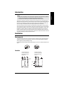
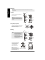
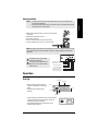
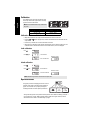
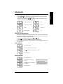
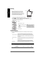
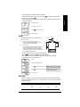
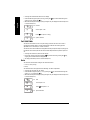
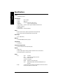
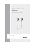
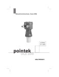
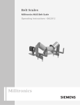
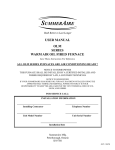
Ultrasonic Transmitters
THE PROBE
Operating Instructions 03/2010
Safety Guidelines: Warning notices must be observed to ensure personal safety as well as that of
others, and to protect the product and the connected equipment. These warning notices are
accompanied by a clarification of the level of caution to be observed.
Qualified Personnel: This device/system may only be set up and operated in conjunction with this
manual. Qualified personnel are only authorized to install and operate this equipment in accordance with
established safety practices and standards.
Unit Repair and Excluded Liability:
•
•
•
•
The user is responsible for all changes and repairs made to the device by the user or the user’s
agent.
All new components are to be provided by Siemens Milltronics Process Instruments Inc.
Restrict repair to faulty components only.
Do not reuse faulty components.
Warning: Cardboard shipping package provides limited humidity and moisture protection. This product
can only function properly and safely if it is correctly transported, stored, installed, set up, operated, and
maintained.
This product is intended for use in industrial areas. Operation of this equipment in a residential area
may cause interference to several frequency based communications.
Note: Always use product in accordance with specifications.
Copyright Siemens Milltronics Process
Instruments Inc. 2010. All Rights Reserved
This document is available in bound version and in
electronic version. We encourage users to purchase
authorized bound manuals, or to view electronic
versions as designed and authored by Siemens
Milltronics Process Instruments Inc. Siemens
Milltronics Process Instruments Inc. will not be
responsible for the contents of partial or whole
reproductions of either bound or electronic versions.
Disclaimer of Liability
While we have verified the contents of this
manual for agreement with the instrumentation
described, variations remain possible. Thus we
cannot guarantee full agreement. The contents
of this manual are regularly reviewed and
corrections are included in subsequent editions.
Please check the website shown below for the
latest manual revisions.
We welcome all suggestions for improvement.
Technical data subject to change.
MILLTRONICS®is a registered trademark of Siemens Milltronics Process Instruments Inc.
Contact SMPI Technical Publications
at the following address:
Technical Publications
Siemens Milltronics Process Instruments Inc.
1954 Technology Drive, P.O. Box 4225
Peterborough, Ontario, Canada, K9J 7B1
Email: [email protected]
•
•
European Authorized Representative
Siemens AG
Industry Sector
76181 Karlsruhe
Deutschland
For a selection of Siemens Milltronics level measurement manuals, go to:
www. siemens.com/level. Choose Instructions and Manuals under the More Info list.
For a selection of Siemens Milltronics weighing manuals, go to:
www. siemens.com/weighing. Choose Support, and then Manuals / Operating Instructions.
© Siemens Milltronics Process Instruments Inc. 2010
Introduction
Notes:
The Probe is an ultrasonic level monitor combining sensor and electronics in a single package. It is
designed to measure liquid levels in closed vessels. The sensor is PVDF or ETFE, allowing The Probe
to be used in a wide variety of industries. The optional sanitary version affords quick removal and
ease of cleaning as demanded by the food, beverage and pharmaceutical industries.
The sensor houses the ultrasonic transducer and temperature sensing element. The Probe emits a
series of ultrasonic pulses from the transducer. Each pulse is reflected as an echo from the material
and sensed by the transducer. The echo is processed by The Probe using Milltronic's proven `Sonic
Intelligence' techniques. Filtering is applied to help discriminate between the true echo from the
material, and false echoes from acoustical and electrical noises and agitator blades in motion. The
time for the pulse to travel to the material and back is temperature compensated and then converted
into distance for display, mA output and relay actuation.
Installation
Environmental
The Probe should be mounted in an area that is within the temperature range specified and that is
suitable to the housing rating and materials of construction. The front lid should be accessible to
allow programming, wiring and display viewing.
It is advisable to keep The Probe away from high voltage or current runs, contactors and SCR control
drives.
Location
Locate The Probe so that
it will have a clear sound
path perpendicular to the
liquid surface
The Probe's sound path
should not intersect the fill
path rough walls, seams,
rungs, etc
fill
fill
sanitary
ferrule
pipe
rungs
seams
7ML19985GD62
The Probe – INSTRUCTION MANUAL
Page 1
mmmmm
•
This product is intended for use in industrial areas. Operation of this equipment in a residential
area may cause interference to several frequency based communications.
The Probe is to be used only in the manner outlined in this instruction manual.
English
•
Mounting
Note: Mount The Probe so that the face of the sensor is at least 25 cm above the highest
English
mmmmm
anticipated level.
Threaded
hinged lid
7 mm
(0.3")
The Probe is available in three thread types:
2" NPT, 2" BSP or PF2.
117 mm
(4.6F")
Note: Before inserting The Probe into its
mounting hole, ensure that the threads are of
the same type to avoid damaging The Probe
threads.
cable entry
’knock out’
84 mm
(3.3") max.
electronics
279 mm
(11")
87 mm
(3.4") ø
mounting
thread
mounting
thread
74 mm
(2.9")
sensor
53 mm
(2.1")
ø max.
61 mm
(2.4")
Flange Adapter (optional)
The Probe can be fitted with the optional 75 mm
(3") flange adapter for mating to 3" ANSI, DIN
65PN10 and JIS 10K3B flanges.
optional
flange
adapter
The Probe
Sanitary
7 mm
hinged lid (0.3")
Notes:• Mount The Probe so that the face of
•
the sensor is at least 25 cm above
the highest anticipated level.
The sanitary Probe is suitable for
chemical clean-in-place
applications to 60 °C (140 °F) only.
Ensure your cleaning chemicals are
compatible with PVDF.
cable entry
’knock out’
61 mm
(2.4")
Note: Inside of sanitary
The Probe
mounting
thread
sensor
76 mm
(2.9")
53 mm
(2.1")
ø max.
4” Sanitary Ferrule
clamp
adjusting
wing nut
ferrule
tank
ferrule must be smooth, free of
burrs, seams or ridges.
Page 2
electronics
279 mm
(11")
87 mm
(3.4") ø
integral
sealing ring
• mount The Probe onto the top of
the tank’s sanitary ferrule
• secure mating by surrounding
the joint with the clamp
• tighten adjusting wing nut
84 mm
(3.3") max.
117 mm
(4.6")
The Probe – INSTRUCTION MANUAL
119 mm (4.68")
97 mm (3.83")
dimensions are approximate
7ML19985GD62
Interconnection
Notes:• Installation shall only be performed by qualified personnel and in accordance with
A. With lid closed, remove cable entry ’knock out’ on either side
as required.
B. Open lid by loosening the lid screw.
C. Run cable to The Probe.
D. Connect mA output, power supply and relay wiring
E. Close lid. Tighten screw to 1.1 to 1.7 N-m (10 to 15 in-lb)
Note: Non-metallic enclosure does not provide grounding between conduit connections. The use
of approved watertight conduit hubs/glands is required for Type 4X / NEMA 4X / IP65 (outdoor)
applications.
All field wiring must have insulation
suitable for at least 250 V.
dc terminals shall be supplied from a
SELV source in accordance with IEC1010-1 Annex H.
mA Output:: 4 to 20 mA non-isolated
into 750 ohms max at 24 V DC
Power Supply: 18 to 30 V DC
Connect to protective earth
Relay: dry contact, closed
unpowered or alarm state, refer
to specifictions on page 19
Operation
Start Up
program mode
alphanumeric
• With The Probe correctly installed (or
aimed at a wall 0.25 to 5 m away), apply
power.
• The Probe starts up displaying the
following:
’20’ key
units
’4’ key
LOE / fault
operation status
• It then defaults to the Run mode, which is the measurement
reading of the distance from the transducer face to the
material level in the units indicated:
• If the default display differs from that shown, refer to
Operation Status on page 4 .
7ML19985GD62
The Probe – INSTRUCTION MANUAL
Page 3
mmmmm
local governing regulations.
Separate cables and conduits may be required to conform to standard instrumentation
wiring practices, or electrical codes.
English
•
English
mmmmm
Calibration
The calibration of the mA output may be done such
that its span will be either proportional or inversely
proportional to the material level.
Note: The 4 and 20 mA levels may be calibrated in
any order.
proportional span
inversely proportional span
high level = 20 mA
high level = 4 mA
low level = 4 mA
low level = 20 mA
Calibration: Reference Method
• Adjust the material level (or target) to the desired distance from the sensor face.
• Press the “4” or “20” key (as appropriate) to view the stored distance associated with that mA
output value.
• Press the key a second time to set the new distance reference.
• After viewing or calibrating, Probe operation automatically reverts to the Run mode (6 sec). The
calibration value is referenced from the face of The Probe sensor, in the units displayed.
4 mA calibration
Press “4”
Press “4” again
4 mA calibration
calibration invalid if
new 4 mA calibration
retry
20 mA calibration
Press “20”
Press “20” again
20 mA calibration
calibration invalid if
new 20 mA calibration
retry
Note: Calibration bypasses the measurement response rate.
Operation Status
The graphic portion of the display gives the user a visual
indication of The Probe's operating status. Viewing the
graphic can assist the user in properly locating and
installing The Probe to achieve optimum performance.
GOOD
WAITING
LOE / FAULT
The logo will change from full to partial to indicate operation status. After the `Waiting' period, the `?'
icon will appear for an `LOE / FAULT' indication. When a valid echo is again received, a `Good'
indication will resume. Refer to Troubleshooting on page 9 .
Page 4
The Probe – INSTRUCTION MANUAL
7ML19985GD62
Adjustments
There are several operating adjustments that can be made to The Probe.
alarm
20 mA calibration, scrolling
fail-safe
blanking
fail-safe timer
speed of response
units
Calibration, Scrolling Method
The 4 and 20 mA calibration values can be selected where reference levels, either from the material
in the vessel or from a target, cannot be provided. This method can also be used to trim the output
levels obtained by the Reference Method (see page 4).
• To change the stored calibration value, obtain the `c 4' or `c 20' display.
• Press the "20" key to increase or the "4" key to decrease the calibration value.
• After scrolling to the desired value, stop pressing the key. The display automatically reverts to the
Run mode (6 sec).
4 mA calibration
4 mA calibration initiated
view stored 4 mA calibration value i.e. 4.50 m
press”20” to increase to new calibration value i.e. 4.60 m
new calibration value
20 mA calibration
20 mA calibration initiated
view stored 20 mA calibration value
i.e. 0.50 m
press “4” to decrease to new calibration
value i.e. 0.45 m
Note: For faster scrolling, hold the
key depressed during the
calibration adjustment and release
when desired value is obtained.
new calibration value
7ML19985GD62
The Probe – INSTRUCTION MANUAL
Page 5
mmmmm
4 mA calibration, scrolling
English
• Press the "4" and "20" keys simultaneously until the desired adjustment is obtained. A viewing
sequence of the stored value is automatically initiated.
• During this time, press either the "4" or "20" key to change the value. After viewing or changing,
operation automatically reverts to the Run mode (6 sec).
English
mmmmm
Blanking
Blanking is used to ignore the zone in front of the
transducer where false echoes are at a level that
interfere with the processing of the true echo. It is
measured outward from the sensor face. The minimum
recommended blanking value is 0.25 m (0.82 ft) but can
be increased in order to extend the blanking.
The Probe
blanking
• To change the stored blanking value, obtain the `bL' display.
• Press the "20" key to increase or the "4" key to decrease the blanking value.
• When the display has scrolled to the desired value, stop pressing the key. The display
automatically returns to the Run mode (6 sec).
blanking
3 sec
stored blanking value i.e. 0.25 m
press “20” to increase blanking i.e. 0.36 m
press “4” to decrease to desired blanking
value i.e. 0.35 m
Note: For faster scrolling, hold
the key depressed during the
blanking adjustment and release
when desired value is obtained.
new blanking value
6 sec
Speed of Response
The speed of response adjustment allows the user to collectively set a number of operating
parameters.
measurement response:
is the limit to which The Probe will be able to keep up with rates of change.
If The Probe measurement cannot keep up with the rate of level change, set the
adjustment from `1' to `2'. If The Probe still cannot keep up with the rate of level
change, set the adjustment option to `3'. Avoid choosing an option that is too fast for
your application.
agitator discrimination:
discriminates between agitator blades in motion, and the material (target) surface.
filter:
discriminates between false echoes from acoustical and electrical noise and the
material (target) surface.
fail-safe timer:
establishes the `Waiting' period from the time a loss of echo or operating fault
condition starts until the fail-safe default is effected. Adjusting the speed of
response will set the fail-safe timer to the default values in the chart. If a different
response is required, adjust the ‘FSt’ option (see page 13).
SP
measurement response
agitator discrimination
filter
fail-safe timer
1*
1 m/min (3.3 ft/min)
on
on
10 min
2
5 m/min (16.4 ft/min)
on
on
3 min
3
immediate
off
off
3 min
4
0.03 m/min (0.1 ft/min)
on
on
10 min
* = factory setting
Page 6
The Probe – INSTRUCTION MANUAL
7ML19985GD62
current option i.e. 1 m/min
press “20” for option 2 i.e. 5 m/min
6 sec option 2 selected
Alarm
The alarm adjustment assigns one of the following
functions to the relay.
O=
loss of echo / fault alarm (factory setting)
The relay is energized with the contacts open during
normal operation (see Fail-safe on page).
Ø=
The Probe
blanking
alarm
setpoint
alarm zone
process alarm
The non zero value entered becomes the alarm setpoint,
referenced to The Probe's sensor face. The relay deenergizes and the contacts close when the material is
within the alarm zone. There is a hysterisis equivalent to
5% of the empty calibration distance.
hysterisis
• To change the alarm function or setpoint, obtain the `AL' display.
• Press the "20" key to increase or the "4" key to decrease the setpoint.
• When the display has scrolled to the desired value, stop pressing the key. The display
automatically returns to the Run mode (6 sec).
3 sec
alarm
stored function i.e. LOE / fault
Press “20” to adjust setpoint i.e. 1.36 m
Note: For faster scrolling, hold the
key depressed during the setpoint
Press “4” to decrease to desired setpoint adjustment and release when the
desired value is obtained.
i.e. 1.35 m
6 sec new alarm value
Fail-Safe
In the event a loss of echo or fault condition exceeds the `Waiting' period (see Speed of Response
on page 6 or Fail-safe Timer below), the ` ? ' icon appears and one of the following fail-safe defaults
is immediately effected.
FLS
default
mAp
mAi
reading
1
full
22
4
hold
2
empty
4
22
hold
3*
hold
hold
hold
hold
p = proportional span
7ML19985GD62
i = inversely proportional span
* = factory default
The Probe – INSTRUCTION MANUAL
Page 7
mmmmm
3 sec speed of response
English
• To change the speed of response, obtain the `SP' display.
• Scroll forward through the options (1-2-3) by pressing the "20" key. Scroll backward through the
options (3-2-1) by pressing the "4" key.
• When the desired option is displayed, stop pressing the key. The display will automatically return
to the Run mode (6 sec).
English
mmmmm
• To change the fail-safe default obtain the `FLS' display.
• Scroll forward through the options (1-2-3) by pressing the "20" key. Scroll backward through the
options (3-2-1) by pressing the "4" key.
• When the desired option is displayed, stop pressing the key. The display will automatically return
to the Run mode (6 sec).
3 sec
fail-safe
current option i.e. full
Press “20” for option 2 i.e. empty
6 sec
option 2 selected
Fail-Safe Timer
The fail-safe timer allows the user to vary the ‘waiting’ period from the time a loss of echo or
operating fault condition begins, until the fail-safe default is effected. The ‘waiting’ period is
adjustable from 1 to 15 minutes, in 1 minute increments.
The fail-safe timer value will default to settings determined by the speed of response (see page 11).
If a different value is desired, the fail-safe timer should be adjusted after the speed of response is
set.
• To change the fail-safe timer, obtain the ‘FSt’ display.
• Increase the ‘waiting’ period by pressing the “20” key, and decrease it by pressing the “4” key,
stopping when the desired value is displayed.
• The display automatically reverts to the Run mode (6 sec).
Units
The units of the measurement reading can be selected as follows:
1 = metres, m (factory setting)
2 = feet, ft
The selected units are also applicable to the `Blanking' and `Alarm' adjustments.
• To change the units obtain the `Un' display.
• Scroll forward through the options ( 1 - 2 ) by pressing the "20" key. Scroll backward through the
options ( 2 - 1 ) by pressing the "4" key.
• When the desired option is displayed, stop pressing the key. The display will automatically return
to the Run mode (6 sec).
3 sec
units
current option i.e. m
Press “20” for option 2 i.e. ft
6 sec
Page 8
option 2 selected
The Probe – INSTRUCTION MANUAL
7ML19985GD62
Supplement
Loading vs. Supply Voltage
The echo is not reliable and The Probe is waiting for a valid echo before updating the
measurement.
Probable causes are:
•
•
•
•
•
•
•
•
material or object in contact with sensor face
The Probe is too close to the fill point
The Probe is not perpendicular to the liquid surface
change in level too fast
measurement out of range
foam on liquid surface
high level of vibration in the mounting structure
level inside the blanking zone
The `Waiting' period has expired. Investigate the probable causes listed above.
Refer to Speed of Response on page or Fail-safe Timer on page 13 for duration of
`Waiting' periods.
Maintenance
The Probe requires no maintenance or cleaning.
Patents
Instrument Housing Design:
•
•
•
•
•
•
Canada:
U.S.A.:
Germany:
U.K.:
France:
Japan:
70345
07/858/707
M92022723
2021748
921873
966217
Electronics / Sensor:
• U.S.A.:
5,267,219
5,339,292
• U.K.:
2,260,059
• patent applications in U.K., Canada, Europe, Africa, Australia
7ML19985GD62
The Probe – INSTRUCTION MANUAL
Page 9
mmmmm
English
Troubleshooting
Specifications
English
mmmmm
Power:
• 18 to 30 V DC, 0.2 A max
Environmental:
• location:
indoor / outdoor
• altitude:
2000 m max.
• ambient
temperature
continuous:-40 to +60 °C (-40 to +140 °F)
-20 °C (-5 °F) if metal mounting
• relative humidity:
suitable for outdoor (Type 4X / NEMA 4X / IP65 enclosure)
• installation category:II
• pollution degree:
4
• process pressure
vented to atmosphere
Range:
• 0.25 to 5 m ( 0.8 to 16.4 ft.), liquids only (standard 24 V model, black label)
• 0.25 to 8 m ( 0.8 to 26.2 ft.) (Extended Range model, green label)
Beam Angle:
• 10° at -3 dB boundary
Memory:
• non-volatile EEPROM, no battery required
Programming:
• 2 tactile keys
Temperature Compensation:
• built-in to compensate over the operating range.
Display:
• liquid crystal
• three 9 mm (0.35") digits for reading of distance between sensor face and material
• multi-segment graphic for operation status
Output
• mA:
range:
4 to 20 mA
span:
proportional or inversely proportional
accuracy: 0.25% of full scale
resolution: 3 mm (0.125")
• Relay:
loading:
750 ohms max at 24 V DC supply
cable:
Belden 8760, shielded, twisted pair, 28 AWG (0.75 mm2) or
equivalent
1 normally closed contact rated at 5 A at 250 V AC non-inductive or 24 V DC
fault on power, application or device failure
Page 10
The Probe – INSTRUCTION MANUAL
7ML19985GD62
Construction:
• combined sensor and electronics package
• sensor housing:
material:
PVDF or ETFE
• electronics housing:material:
access:
flanged:
flange adapter, threaded Probe to 3" ANSI, DIN
65PN10 and JIS 10K3B
sanitary:
4" sanitary ferrule with integral sealing ring c/w 304
stainless steel clamp (5 m model only)
PVC
hinged lid
22 mm (0.87") dia. `knock out' for conduit entrance, 2 places
6 screw terminal block for 2.5 mm2 (14 ga) solid wire / 1.5 mm2
(16 ga) stranded wire max
Enclosure Rating:
• Type 4X / NEMA 4X / IP65
Weight:
• 1.7 Kg (3.7 lb)
Approvals:
• CE*, C-TICK, FM, CSAUS/C
* EMC performance available on request.
7ML19985GD62
The Probe – INSTRUCTION MANUAL
Page 11
mmmmm
threaded: 2”NPT, 2" BSP PF2
English
mounting:
www.siemens.com/processautomation
For more information
www.siemens.com/level
www.siemens.com/continuous-weighing
Siemens Milltronics Process Instruments Inc.
Industry Automation (IA)
1954 Technology Drive
P.O. Box 4225
Peterborough, ON
Canada K9J 7B1
Subject to change without prior notice
7ML19985GD62 Rev. 2.0
© Siemens Milltronics Process Instruments Inc. 2010
email: [email protected]
www.siemens.com/processautomation
*7ml19985GD62*
Printed in Canada