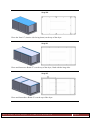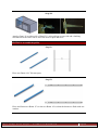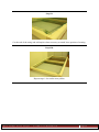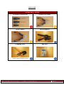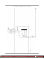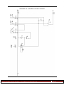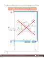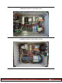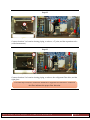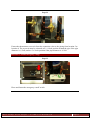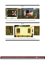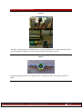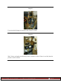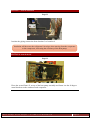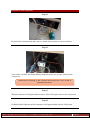
1
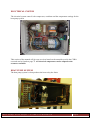
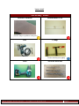
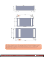
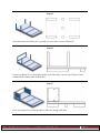
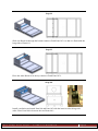
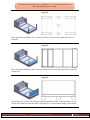
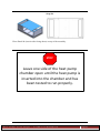
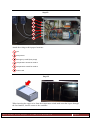
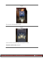
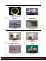
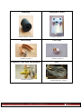
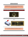
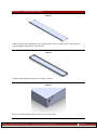
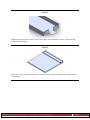
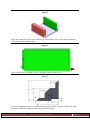
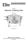
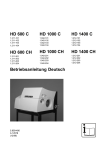
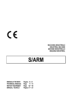
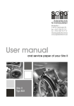
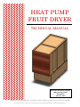
HEAT PUMP FRUIT DRYER TECHNICAL MANUAL Worcester Polytechnic Institute NTB University, Buchs Ӧkozentrum April 30th, 2015 WRITTEN BY: CASEY BROWN, ZACHARY LIPSKY, MARIANA VERTONI, KATHRYN ZIEGLER To request a copy of this user manual, please contact Stefan Bertsch at [email protected] TABLE OF CONTENTS TECHNICAL HANDBOOK OVERVIEW ........................................................................... 1 CHAPTER 1: MACHINE OVERVIEW ............................................................................... 2 FINAL ASSEMBLY ............................................................................................................................... 2 CHAMBERS AND PALLETS ................................................................................................................. 3 ELECTRICAL SYSTEM .......................................................................................................................... 4 HEAT PUMP SYSTEM ......................................................................................................................... 4 CHAPTER 2: SAFETY CONCERNS ................................................................................... 6 CHAPTER 3: INSTALLATION ............................................................................................ 7 CHAMBERS AND PALLETS ................................................................................................................. 7 PARTS LIST..................................................................................................................................... 7 TOOLS LIST .................................................................................................................................... 9 ASSEMBLY INSTRUCTIONS .......................................................................................................... 10 ELECTRICAL SYSTEM ........................................................................................................................ 33 PARTS LIST................................................................................................................................... 33 TOOLS LIST .................................................................................................................................. 38 ASSEMBLY INSTRUCTIONS .......................................................................................................... 40 HEAT PUMP SYSTEM ....................................................................................................................... 54 PARTS LIST................................................................................................................................... 54 TOOLS LIST .................................................................................................................................. 58 ASSEMBLY INSTRUCTIONS .......................................................................................................... 62 CHAPTER 4: OPERATIONS .............................................................................................. 78 TOOLS LIST .................................................................................................................................. 78 PREPARATION INSTRUCTIONS .................................................................................................... 78 FRUIT ANALYSIS .......................................................................................................................... 84 TECHNICAL HANDBOOK OVERVIEW This handbook was created to guide the user through the construction and operation of the heat pump fruit dryer. Before any assembly, read the safety concerns in Chapter 2 carefully. Chapter 1 is an overview of the three sub-assemblies of the fruit dryer (chambers and pallets, electrical system, and heat pump system). Chapter 3 describes the construction steps for each of the three sub-assemblies. Chapter 4 outlines the procedures to operate the dryer once installation is complete. Keep in mind the following important considerations when using this manual: The manual was designed assuming that carpenters will build the chambers and pallets, electricians will assemble the electric system, and air conditioning technicians will assemble the heat pump system. The manual was written to provide enough information for the dryer to be assembled from parts that are ordered and fabricated on-site, without any components or subassemblies shipped. The dryer can be adapted to suit the resources and materials available in the community where it is implemented. Aspects of the fruit dryer that can be readily modified are noted throughout the manual. The necessary tools to build the dryer can also be adapted to suit the availability of tools at each location. The recommended tools in the list provided in the handbook have been labeled with the following priority rank: High: necessary to complete the fruit dryer. Medium: perform a task necessary to complete the fruit dryer, but can be replaced by a tool of similar function. Low: not necessary, but reduce time to construct the fruit dryer. The manual includes drying instructions for apples and mangoes. Different fruits and vegetables can be dried, but make sure to adjust the preparation steps and drying time accordingly. The crucial aspect when constructing the drying chamber is to guarantee it is air tight, waterproof, and food safe (even at high temperatures). The evaporator, condenser, compressor, and ventilator are unique to the fruit dryer's heat pump system and must follow exact specifications before any modification occurs. The product codes of the electrical components shown in the parts list of the electrical system pertain to specific manufacturers. These codes will change if similar components are purchased from different manufacturers. Heat Pump Fruit Dryer - Technical Handbook Page 1 CHAPTER 1: MACHINE OVERVIEW FINAL ASSEMBLY 1 2 4 3 5 Heat Pump Fruit Dryer - Technical Handbook Page 2 CHAMBERS AND PALLETS The chambers and pallets make up the structure of the fruit dryer and are comprised of the heat pump chamber, drying chamber, and pallet assembly. This section of the manual will be based on the fruit dryer framework built at NTB University in April 2015 and can be found on page 7. The drying and heat pump chambers in this manual were made with laminated wood, however this is not necessary as long as the chambers are waterproof. This can also be accomplished by lining the drying chamber with foil or replacing the wooden panels with metal. The drying chamber also needs to be air-tight, with a material that is food safe on the inside. The important areas in which to keep an airtight seal are the corners of the drying chamber shown below. All chamber and pallet components can be adapted to the resources available. Heat Pump Fruit Dryer - Technical Handbook Page 3 ELECTRICAL SYSTEM The electrical system control’s the compressor, ventilator and the temperature settings for the heat pump system. This section of the manual will give an overview based on the materials used in the CUBO case and can be found on page 33. All electrical components can be adapted to the resources available. HEAT PUMP SYSTEM The heat pump system is what produces the heat to dry the fruits. Heat Pump Fruit Dryer - Technical Handbook Page 4 The evaporator, condenser, compressor, and ventilator are specific to this fruit dryer. Exact specifications are indicated on the parts list that starts on page 54. All other heat pump components can be adapted to the resources available. Approximate timeframe for each sub-assembly Name of section Number of people required Heat pump chamber 1 Drying chamber 1 Pallets 2 Electrical system 1 Placing heat pump components 1 Heat pump piping 1 Prepping the heat pump system 1 Operations 2 Heat Pump Fruit Dryer - Technical Handbook Time required 16 hrs. 16 hrs. 20 hrs. 6 hrs. 2 hrs. 6 hrs. 24 hrs. 20-30 hrs. Page 5 CHAPTER 2: SAFETY CONCERNS Caution: can cause minor or moderate injury. Warning: can cause death or serious injury. All edges of the wooden panels must be filed or sanded to remove sharp edges and corners. When operating heavy machinery (i.e. saws, drills, and grinders), use the utmost awareness to prevent serious injury. The ends of the aluminum rail for mounting electrical components must be filed to remove dangerous sharp edges. The fins in the evaporator and condenser are extremely sharp and should not be touched with bare hands. The water that is produced from the evaporator is deionized and not safe for drinking. Keep liquids away from all electrical components. Spills can cause electric shocks and can damage the electrical equipment. When working with electrical components, always disconnect the power source from any equipment beforehand to avoid electric shock hazards. When working with brazing equipment, be aware of high temperatures that can cause serious burns or lesions. Be aware that refrigerant leaks are not only harmful for the environment, but can also cause nausea and headaches. Cutting tools for preparing the fruit are extremely sharp, so use with caution. When removing pallets from the fruit dryer, make sure that two people are grasping each side of the pallet to reduce the risk of injury. After the heat pump is set up, be aware that the pipes running from the evaporator to the condenser will be extremely hot. Heat Pump Fruit Dryer - Technical Handbook Page 6 CHAPTER 3: INSTALLATION CHAMBERS AND PALLETS PARTS LIST Hardware for Chambers (total) Dimensions (mm) 5 x 20 Flat Head 5 x 25 Flat Head 5 x 35 Flat Head 5 x 60 Flat Head 5 x 80 Flat Head 6 x 100 Flat Head 8.5/35/2.5 M5 N/A N/A Hardware for Pallets Name Dimensions (mm) Screw 06 3 x 16 Screw 07 6 x 120 Mosquito netting 730 x 1345 Wire 11580 String 2940 Heat Pump Chamber Name Dimensions (mm) Panel 01 15 x 970 x 1700 Panel 02 15 x 540 x 970 Panel 03 15 x 445 x 540 Panel 04 15 x 445 x 840 Panel 05 15 x 445 x 840 Panel 06 15 x 220 x 940 Panel 07 15 x 445 x 940 Panel 08 15 x 970 x 1700 Panel 09 15 x 460 x 1110 Panel 10 15 x 540 x 1730 Panel 11 15 x 540 x 970 Panel 12 15 x 460 x 1110 Panel 13 15 x 540 x 1730 Beam 01 100 x 100 x 100 Beam 02 100 x 100 x 500 Beam 03 50 x 50 x 870 Beam 04 50 x 50 x 1700 Beam 05 50 x 50 x 460 Beam 06 50 x 50 x 970 Beams Wooden Panels Name Screw 01 Screw 01 Screw 02 Screw 03 Screw 04 Screw 05 Washer 01 Nut 01 Hinge Door clamps Heat Pump Fruit Dryer - Technical Handbook Number Required 18 27 85 87 35 8 39 39 3 3 Number Required 230 120 10 10 10 Number Required 1 1 2 1 1 1 1 1 1 1 2 1 1 3 4 7 2 6 2 Page 7 Wooden Panels Beams Beams Name Panel 14 Panel 15 Panel 16 Panel 17 Panel 18 Panel 19 Panel 20 Beam 03 Beam 07 Beam 08 Beam 09 Beam 10 Beam 11 Beam 12 Beam 13 Name Beam 14 Beam 15 Beam 16 Drying Chamber Dimensions (mm) 15 x 970 x 1900 15 x 1235 x 1900 15 x 840 x 1235 15 x 970 x 1900 15 x 840 x 1592 15 x 970 x 1315 15 x 375 x 1315 50 x 50 x 870 50 x 50 x 1900 50 x 50 x 1200 50 x 50 x 870 50 x 50 x 1117 50 x 50 x 1135 35 x 42 x 1592 50 x 60 x 840 Pallets Dimensions (mm) 35 x 40 x 1435 50 x 50 x 1535 50 x 60 x 730 Number Required 1 2 1 1 1 2 2 7 4 8 2 2 2 2 1 Number Required 2 2 3 This drying and heat pump chambers were built with laminated wooden panels of 1.5 cm thickness. Other thicknesses can be used, but the dimensions shown in the table need to be adjusted accordingly. The chambers can also be made of metal or lined with foil. The choice of the material needs to ensure that the drying chamber is air-tight, waterproof, and food safe. Heat Pump Fruit Dryer - Technical Handbook Page 8 TOOLS LIST Necessary Tools Abrasive Material Measurement Tool Used to shape or polish a work piece Saw Drill Heat Pump Fruit Dryer - Technical Handbook Clamp Used to hold objects tightly together) Assorted Drill Bits Page 9 Countersink Drill Bit Used to widen the entrance of a hole to allow for the screw head to sit flush with the surrounding material. ASSEMBLY INSTRUCTIONS SECTION 1: Prepare the wooden panels and beams Step #1: Cut the wooden panels and beams Cut the wooden panels and beams, following the example above: 1. Use the drawings that follow to mark the cuts on the wooden panels and beams. 2. Cut the wooden panels and beams according to the specified dimensions (all in mm). Heat Pump Fruit Dryer - Technical Handbook Page 10 Panel 02 Panel 03 Panel 04 Panel 05 Heat Pump Fruit Dryer - Technical Handbook Page 11 Panel 06 Panel 08 Panel 14 The 210 mm dimension for one of the openings in Panel 08 and Panel 14 is designed to match the dimensions of the ventilator that is chosen for the dryer (see section on the heat pump system). If a different ventilator is selected, this dimension must be adjusted to suit the dimensions of the ventilator. Heat Pump Fruit Dryer - Technical Handbook Page 12 Panel 12 Panel 13 Panel 15 Heat Pump Fruit Dryer - Technical Handbook Page 13 Panel 16 Panel 17 Beam 09 Heat Pump Fruit Dryer - Technical Handbook Page 14 Panel 18 Step #2: Sand 1. File the wooden panels. 2. File the beams. Heat Pump Fruit Dryer - Technical Handbook Page 15 SECTION 2: Assemble the heat pump chamber Example Step All steps described in Sections 2 and 3 are formated as shown: The image on the left depicts the piece (in blue) that is being added to the system. The image on the right shows the placement of all screws in that piece. Note that since dimensions are not specified, an approximate placement is sufficient. Step #1 Place and fasten four Beam 02’s under Panel 01 (interior side of the panel facing up). Always countersink the holes so that the tops of the screw heads will be flush with the surface. The reference “Interior Side” indicates the side of the wood that is water resistant and food safe. If the inside of the drying chamber will be lined with other materials that fit the requirements, disregard orientation. Heat Pump Fruit Dryer - Technical Handbook Page 16 Step #2 Place and fasten the three Beam 01’s under the center of the wooden panel. Step #3 1. Lay and fasten two Beam 04’s lengthwise so that they are flush with the sides of Panel 01. 2. Lay five Beam 03’s across Panel 01 between the Beam 04’s. Step #4 Place and fasten Panel 02 (interior side facing up) on top of the beams, flush with the end of the dryer. Heat Pump Fruit Dryer - Technical Handbook Page 17 Step #5 Place and fasten four Beam 05’s upwards in each of the corners of Panel 02. Step #6 Fasten two Beam 03’s to be flush with the end of the dryer: one on top of Panel 02 and another flush with the tops of Beam 05’s. Step #7 Place two Panel 03’s so that the interior sides are facing each other. Heat Pump Fruit Dryer - Technical Handbook Page 18 Step #8 Slide one Beam 06 through the bottom cutouts of both Panel 03’s so that it is flush with the long sides of Panel 01. Step #9 Place the other Beam 06 in the top cutouts of both Panel 03’s. Step #10 Install ventilation and attach Panel 04 and Panel 05 with the interior sides facing each other. Place Panel 04 in between the two Beam 06’s. Heat Pump Fruit Dryer - Technical Handbook Page 19 For details on instalation of the ventilation, see ‘Assembly Instructions’ in the ‘Heat Pump System’ section. Step #11 Place and fasten two Beam 05’s oriented vertically in each of the remaining corners of Panel 01. Step #12 Place and fasten Panel 06 (interior side up) flush with the end of the dryer that is opposite of Panel 05. Step #13 Attach Panel 07 (interior side facing inwards) against the insides of the Beam 05’s on top of Panel 06. Make sure that the sides of the plate are 15 mm from the edges of the beams. Heat Pump Fruit Dryer - Technical Handbook Page 20 Step #14 Place Panel 08 (interior side facing down) on top of the assembly. STOP Leave one side of the heat pump chamber open until the heat pump is inserted into the chamber and has been tested to run properly. Heat Pump Fruit Dryer - Technical Handbook Page 21 Step #15 Place and fasten Panel 09 (interior side facing inwards) to fit on the right side of the chamber, and fasten Panel 12 similarly on the left side of the chamber. Step #16 Place and fasten Panel 10 (interior side facing out) to the exterior of Panel 09 and Panel 13 to the exterior of Panel 12. Step #17 Place and fasten two Panel 11’s (interior side facing out) to the short ends. Heat Pump Fruit Dryer - Technical Handbook Page 22 SECTION 3: Assemble the drying chamber Step #1: Place Panel 14 interior side facing up. Step #2 Place and fasten two Beam 07’s flush with the long sides of Panel 14. Step #3 Place and fasten eight Beam 08’s oriented vertically to the two Beam 07’s. These are drilled from the BOTTOM of Panel 14. Heat Pump Fruit Dryer - Technical Handbook Page 23 Step #4 Place and fasten three Beam 03’s on Panel 14: two flush with either end of the drying chamber and one aligned with two Beam 08’s. Step #5 Place and fasten the two Beam 09’s that were cut to the interior side of Panel 14, with the cut sides facing up and one end flush with the edge of the 210 x 840 cutout. Step #6 Place and fasten two Beam 10’s flush with the corners of the 210x840 cutout of Panel 14 Heat Pump Fruit Dryer - Technical Handbook Page 24 Step #7 Place and fasten Beam 03 between the two Beam 08’s 15 mm from the top of the beams. Step #8 Place and fasten the two Panel 15’s (interior sides facing each other) oriented vertically on the interior sides of the Beam 08’s. Step #9 Place and fasten Panel 16 (interior side facing inwards) oriented vertically against the two Beam 03’s. Heat Pump Fruit Dryer - Technical Handbook Page 25 Step #10 Place the Panel 17 (interior side facing down) on the top of the dryer. Step #11 Place and fasten two Beam 07’s on the top of the dryer, flush with the long sides. Step #12 Place and fasten three Beam 03’s on the top of the dryer. Heat Pump Fruit Dryer - Technical Handbook Page 26 Step #13 Place and fasten Panel 18 (interior side facing up) on top of the Beam 09’s and Beam 10’s so that it is flush with the back of the dryer. Make sure that the holes are not blocked by the beams. Step #14 Place and fasten two Beam 11’s against Panel 16 so that they are between both Beam 03’s. Step #15 Place and fasten Panel 19 to the Beam 03s and Beam 08’s. Heat Pump Fruit Dryer - Technical Handbook Page 27 Step #16 Place and fasten Beam 12’s to the interior side of Panel 18, flush with either end. Step #17 Both sides Place and fasten Beam 13 so that it is on the interior side of the Panel 15’s. Step #18 Place and fasten two Panel 19’s to the Beam 08’s so they are flush with the top and bottom of the Beam 07’s. Heat Pump Fruit Dryer - Technical Handbook Page 28 Step #19 Attach a Panel 19 to either side of Panel 21’s using a hinge on one side and a latching mechanism on the other side to allow the door to open and close. SECTION 4: Assemble the pallets Step #1: Place two Beam 14’s 760 mm apart. Step #2: Place and fasten two Beam 15’s to the two Beam 14’s so that the beams are flush with one another. Heat Pump Fruit Dryer - Technical Handbook Page 29 Step #3: Place and fasten three Beam 16’s in between the two Beam 15’s. Step #4: Drill 6 screws into the Beam 16’s on the outer edges of the pallet that are 10 cm apart. Leave enough room beneath the screw head to wrap wire around the screw. Step # 5: Wrap wire around the screws and tie off both ends. Heat Pump Fruit Dryer - Technical Handbook Page 30 Step #6: Tighten the wire by placing additional screws in the locations shown to take up slack. Tighten all screws. Step #7: Staple the ends of the netting on one corner of the pallet. Step #8: Run string along the inner edge of the pallet and fold the edge of the netting around the string, then staple the netting and string to the pallet. Heat Pump Fruit Dryer - Technical Handbook Page 31 Step #9: Cut the end of the string and add staples when necessary to attach loose portions of netting. Step #10: Repeat steps 1-9 to make more pallets. Heat Pump Fruit Dryer - Technical Handbook Page 32 ELECTRICAL SYSTEM One-phase System Three-phase System The power components shown in this section are based on a three-phase system. A one-phase system can be adapted with the addition of a capacitor. Schematics for both phases are provided at the end of the section. PARTS LIST Name Screw 06 Screw 07 Screw 08 Screw 09 Wire 01 Wire 02 Hardware for Electrical components Dimensions (mm) Number Required 3 x 20 16 3.5 x 20 4 5 x 45 12 5 x 60 3 1.5 4.5 meters 0.75 12 meters Electrical Components Electrical Case (CUBO O 300x400x180) Dimensions (cm): 30 x 40 x 18 Number required: 1 Heat Pump Fruit Dryer - Technical Handbook Mounting plate (Lochplatte 270x370) Dimensions (cm): 27 x 37 Number required: 1 Page 33 Wall mounting brackets (Wandbef.lasche zu CUBO) Lock nut M20 (Gegenmutter Polyamid M20Agro) Number required: 7 Number required: 1 Cable gland M20 (Polyam.-Verschraub.M20 Agro) Power cord (Cable 3*2.5mm2) Number required: 7 Circuit breaker for the compressor* (LS-Schalter Hager C 6KA 3P 10A) Number of wires: 3 Contactor (DIL EM 10 (230VAC)) Number required: 1 Heat Pump Fruit Dryer - Technical Handbook Number required: 1 Page 34 Feed-through terminal block** (R-Klemme 4mm2) Ground terminal (Trennwand) Number required: 14 grey, 3 blue Number required: 6 Ground partition (Erdklemme 4 mm2, blank) Locking piece (Arretierstuck) Number required: 6 Number required: 6 Circuit breaker for the ventilator (LS C6A 1pol) Multifunction time relays (CS2/UC12-240V) Number required: 6 Number required: 1 Heat Pump Fruit Dryer - Technical Handbook Page 35 Switch for the ventilator Switch for the 2 temperature modes (P220-61062-003M1-S) (P220-61025-003M1) Number required: 1 Number required: 1 Transformer Potentiometer (RLTS80) (SP-01/1M) Number required: 1 Number required: 1 Emergency Cutoff (PS2-W7A) Adapter rail for terminalys and relays (Hutschiene 35mm) Number required: 1 Heat Pump Fruit Dryer - Technical Handbook Dimensions (cm): 3.2 x 0.37 Number required: 2 Page 36 Capacitor for the fan (GC 6uF) Analog temperature meaurement Number required: 1 Number required: 1 Temperature switches (heatTHERM-AT) Number required: 2 * Picture shown is for a three-phase system, but one-phase can be used as well (LS C13A 1pol) ** Can be replaced with simple soldering Heat Pump Fruit Dryer - Technical Handbook Page 37 TOOLS LIST Necessary Tools Assorted Screwdrivers Needle-Nose Pliers Wire Cutters Wire Strippers Crimping Tool Zip-Ties Used to fasten crimps to wires Heat Pump Fruit Dryer - Technical Handbook Page 38 Drill Assorted Large Diameter Drill Bits Used to cut holes in the plastic electrical case Deburring Tool Used to remove sharp edges from metals or plastics Heat Pump Fruit Dryer - Technical Handbook Page 39 ASSEMBLY INSTRUCTIONS SECTION 1: Assemble the plastic case for electronics Step #1: Attach the case extension using the four black threaded pegs. Step #2: Tighten the threaded pegs using the grey screwdriver fitting provided. Heat Pump Fruit Dryer - Technical Handbook Page 40 Step #3: Drill Mark and drill 6 evenly spaced 20 mm diameter holes for cable fittings that are approximately 4 cm from the bottom of the case. There are two templates attached on the following pages that can be used as a guide for the drilling in steps #3 and #4. Step #4: Drill Mark and drill 4 holes 5 mm in diameter for each switch plate. Step #5: Drill Mark and drill a 20.5 mm hole for the potentiometer. Heat Pump Fruit Dryer - Technical Handbook Page 41 Heat Pump Fruit Dryer - Technical Handbook Page 42 Heat Pump Fruit Dryer - Technical Handbook Page 43 SECTION 2: Assemble the components within the electrical case Step #1: Remove sharp edges File the ends of the aluminum rail for placing electrical components. Step #2: Drill Tap three M4 thread size holes in the metal screen for mounting the aluminum rail. Step #3: Screw Drill three holes (diameter 4.5 mm) in the aluminum rail and mount the rail on the metal screen with screws that correspond to the size of the tapped holes. Heat Pump Fruit Dryer - Technical Handbook Page 44 Step #4: Place Terminals Follow electrical schematics on the following pages, and attach the terminals to the aluminum rail. Begin by attaching the transparent terminal that acts as a stopper to the left end of the aluminum rail. Step #5: Label Label the terminals as shown in the appropriate schematics. Step #6: Wire Cut wires to connect the components as shown in the schematics. Strip the wire ends, place end fittings, and crimp the wires before inserting them into the cages. If the wire insulation is pinched in the cages, a full contact might not be made with the wire. Heat Pump Fruit Dryer - Technical Handbook Page 45 Schematic for a one-phase system: Compressor Heat Pump Fruit Dryer - Technical Handbook Page 46 Schematic for a one-phase system: Ventilator Heat Pump Fruit Dryer - Technical Handbook Page 47 Schematic for a one-phase system: Controller Heat Pump Fruit Dryer - Technical Handbook Page 48 Schematic for a three-phase system: Controller The schematics for the compressor and ventilator for a three-phase system are the same as the ones for a one-phase system. 1F3 3K4 1 3 5 2 4 6 M 3~ Heat Pump Fruit Dryer - Technical Handbook Page 49 Completed circuit for a one-phase system Completed circuit for a three-phase system Heat Pump Fruit Dryer - Technical Handbook Page 50 SECTION 3: Attach the electrical components to the dryer Step #1: Attach the electrical case, analog temperature gauge, and two temperature switches to the front Panel 11 of the dryer. STOP Move on to the heat pump system assembly before continuing this section in order to wire electrical components to the heat pump. Heat Pump Fruit Dryer - Technical Handbook Page 51 Step #2: Attach the wiring to their proper locations: Fan Compressor Emergency cutoff (heat pump) Temperature switch for mode 1 Temperature switch for mode 2 : Power cord : Step #3: When inserting the copper wire from the temperature switch make sure that it goes through the fan chamber, into the center to the ventilator. Heat Pump Fruit Dryer - Technical Handbook Page 52 Step #4: Wire the inside of the temperature switches. Step #5: Set the maximum and minimum range of the temperature controls: Temperature switch for mode 1: 35-73 ºC Temperature switch for mode 2: 25-45 ºC Heat Pump Fruit Dryer - Technical Handbook Page 53 HEAT PUMP SYSTEM PARTS LIST Name Hardware for Heat pump assembly (total) Dimensions (mm) Screw 10 Screw 11 Screw 12 Screw 13 Screw 14 Screw 15 Screw 12 Washer 02 Washer 03 Washer 01 Washer 04 Nut 02 Rivet Elbow Joints Tubing Threaded Slotted Insert Wooden Panels Piping Name Panel 21 M4 x 10 Machine Screw M4 x 35 Machine Screw 4.5 x 20 Pan Head 4.5 x 45 Pan Head 5 x 20 Pan Head M6 x 20 Machine Screw M8 x 40 Machine Screw 4.3/12/1 5.3/15/1.2 5.4/15/1.2 8.5/35/2.5 M4 2.4 or 3.0 ½ Zoll – ¾ Zoll Diameter: 3.5 Length: 2000 Inside diameter: M8 Outside diameter: M12 Length: 18 Diameter: 6.4 Diameter: 8 Diameter: 12.6 Diameter: 19 Parts Dimensions (mm) 24 x 940 x 940 Heat Pump Fruit Dryer - Technical Handbook Number Required 30 4 20 4 6 4 4 54 12 16 4 34 8 5 Length: 2000 mm 4 Length: 39.7 mm Length: 10 mm Length: 100 mm Length: 112 mm Number Required 2 Page 54 The compressor, condenser, evaporator, and ventilator must be ordered as specified. Heat Pump Components Compressor Number required: 1 3 Flow Rate: 6.8 𝑚 ⁄ℎ Must be able to sustain: Evaporator temperature: 25ᵒC Condenser temperature: 65ᵒC Condenser Number required: 1 Total surface area: 10 𝑚2 Fin Spacing > 3.5 𝑚 Overall heat rate trasnfer: 8 kW Dimensions: 920 x 410 x 160 mm Evaporator Ventilator Number required: 1 Total surface area: 10 𝑚2 Fin Spacing > 3.5 𝑚 Overall heat rate trasnfer: 6 kW Dimensions: 920 x 410 x 90 mm Number required: 1 3 Flow Rate: 1500 𝑚 ⁄ℎ Pressure: 80 Pa Temperature: 70ᵒC Variable Speed Dimensions: Thickness 216mm Outside Diameter 330mm Heat Pump Fruit Dryer - Technical Handbook Page 55 Metal Shroud Number required: 1 Dimensions: match ventilator Sight Glass Number required: 1 Pressure Valve Dimensions: ¾” Number required: 1 Schrader Valve Core Number required: 2 Heat Pump Fruit Dryer - Technical Handbook Refrigerant Filter Drier Number required: 1 Metal Bracket Number required: 2 or 4 Pressure Valve Dimensions: ½” Number required: 1 T Joint Number required: 2 Page 56 Insulation Emergency Cutoff Length required: 1 meter Number required: 1 Metal Strap Valve Seal Number required: 1 Expansion Value with Thermometer Number required: 1 Heat Pump Fruit Dryer - Technical Handbook Number required: 4 Wire Length required: 1.5 meter Page 57 TOOLS LIST Necessary Tools Abrasive Material Measurement Tool Used to shape or polish a work piece Metal Saw Drill Heat Pump Fruit Dryer - Technical Handbook Metal Cutter Brazing Equipment Page 58 Countersink Drill Bit (High) Assorted Drill Bits Used to drill out the end of an open pipe to allow the solder to better fill the pipe joint. Pipe Cutter Pipe Bender Cleaning Material Deburring Tool Pipe Expander Compressed Air Hose Heat Pump Fruit Dryer - Technical Handbook Page 59 Hammer Pressure Monitor Grinder Solder & Flux Vacuum Pump Riviter Bench Vice Allen Wrench Heat Pump Fruit Dryer - Technical Handbook Page 60 Insulation Tape Insulation Glue Electrical Tape Wrench Assorted Screwdrivers Heat Pump Fruit Dryer - Technical Handbook Page 61 ASSEMBLY INSTRUCTIONS It is highly important to clean all piping component through the process of building the heat pump system. Foreign contaminants could restrict or damage the operation of the system. SECTION 1: Install ventilation Step #1 Center and fasten the metal shroud on Panel 04 (interior side up). Step #2 Overhead view Place and fasten the ventilator in place by securing it to Panel 05 and the Metal Shroud. Adjust the ventilator accordingly to prevent rubbing from occuring between the ventilator fan and the shroud when the fan is spinning. Heat Pump Fruit Dryer - Technical Handbook Page 62 SECTION 2: Construct water collector Step #1 Obtain a metal sheet measuring 190 x 1000 mm in area. Cut the corners of the sheet to create foldable sides that are 30 mm tall. Step #2 Fold the sides up and create four 90 degree corners. Step #3 Rivet each side of the corners with 2.4 or 3.0 mm rivets. Heat Pump Fruit Dryer - Technical Handbook Page 63 Step #4 Make two cuts near the center of one end of the water collector to create a spout for the water to exit through. Step #5 Place the water collector on Panel 21 so that the back corner is flush with the back corner of the panel. Heat Pump Fruit Dryer - Technical Handbook Page 64 SECTION 3: Fasten condenser, compressor, and evaporator Step #1 Attach four 90 degree metal brackets to the flanges on the condenser that are facing the evaporator. Be careful to not puncture any of the metal tubing while drilling. For safety, file the holes after drilling to remove sharp edges. Step #2 Insert rubber bushings into the mounting points for the compressor. Heat Pump Fruit Dryer - Technical Handbook Page 65 Step #3 Place and fasten the compressor using the threaded slotted inserts, and the Washer 04’s. This washer size is crucial to hold the compressor securely in place if the fruit dryer is transported. Step #4 Place and fasten the condenser on Panel 21 (interior side facing up) with the back edge of the condenser flush with the edges of the panel. Heat Pump Fruit Dryer - Technical Handbook Page 66 Step #5 Place the evaporator in the water collector so that its back corner is also aligned with the back corner of the collector plate. Step #6 Drill a hole in the rear flange of the evaporator to allow for the rivet. Step #7 Cut two triangular pieces of wood and make the required cuts as shown. These will act as brackets to hold the evaporator and water collector in place. Heat Pump Fruit Dryer - Technical Handbook Page 67 Step #8 Fasten the wooden brackets in place. Heat Pump Fruit Dryer - Technical Handbook Page 68 SECTION 4: Assemble the piping Side View Each number represents a connecting location in the heat pump system. Step #1 Top View Side View Connect location 1 to location 2 using piping, a reducer, and a T joint. Allow for enough additional piping to dampen vibrations and reduce the risk of failure. Heat Pump Fruit Dryer - Technical Handbook Page 69 Step #2 Top View Side View Connect location 3 to location 4 using piping, a reducer, a T joint, and the expansion valve (with thermometer). Step #3 Top View Side View Connect location 5 to location 6 using piping, a reducer, the refrigerant filter drier, and the sight glass. This filter dryer must be oriented to match the refrigerant flow direction. A label on the filter indicates the proper flow direction. Heat Pump Fruit Dryer - Technical Handbook Page 70 Step #4 Side View Front View Fasten the thermometer reservoir from the expansion valve to the piping from location 5 to location 6. The reservoir must be oriented at a 1 o’clock position around the pipe if the pipe diameter is ½ Zoll, and at a 3 o’clock position if the pipe diameter is ¾ Zoll. SECTION 5: Install emergency cutoff Step #1 Top View Side View Place and fasten the emergency cutoff switch. Heat Pump Fruit Dryer - Technical Handbook Page 71 Step #2 Top View Side View Connect location 7 to location 2 and location 8 to location 3 using flexible tubing. Step #3 Set the pressure minimum to 1.5-2.0 bar and the pressure maximum to 20-25 bar. Heat Pump Fruit Dryer - Technical Handbook Page 72 SECTION 6: Perform pressure test Step #1 Attach a vacuum pump to the high and low pressure fittings on the compressor and run the vacuum pump overnight to remove moisture from the heat pump system. Step #2 Check the sight glass after the vacuum test is completed to make sure that the system is DRY. Heat Pump Fruit Dryer - Technical Handbook Page 73 Step #3 Use pressurized nitrogen to pressurize the system to 10 bar. Step #4 Wait 5 hours, and make sure that the pressure remains at 10 bar. If there is no leak, then the pressure can be released. Heat Pump Fruit Dryer - Technical Handbook Page 74 SECTION 7: Attach insulation Step #1 Insulate the piping connection from location 3 to location 4. Insulation will decrease the refrigerant’s heat loss when moving from the evaporator to the compressor, increasing the efficiency of the heat pump. SECTION 8: Attach the lid Step #1 Place the second Panel 21 on top of the heat pump assembly and fasten it to the 90 degree metal brackets on the condenser and evaporator. Heat Pump Fruit Dryer - Technical Handbook Page 75 SECTION 9: Add refrigerant Step #1 Re-attach the vacuum pump and create a vacuum in the system to remove moisture. Step #2 Turn on the ventilator and begin adding refrigerant to the low pressure fitting on the compressor. Instructions for turning on the ventilator and compressor can be found in Operations Section 3. Step #3 When the amount of refrigerant added reaches 1000-1500 grams, turn on the compressor. Step #4 Gradually add refrigerant until the amount of refrigerant added reaches 2200 grams. Heat Pump Fruit Dryer - Technical Handbook Page 76 Step #5 Disconnect the refrigerant hoses and check the sight glass to make sure that the color depicts DRY and that there are no bubbles visible. Step #6 Adjust the regulator in the expansion valve as necessary to prevent overheating of the system. Heat Pump Fruit Dryer - Technical Handbook Page 77 CHAPTER 4: OPERATIONS The manual includes drying instructions for apples and mangoes. Different fruits and vegetables can be dried, but make sure to adjust the preparation steps and drying time accordingly. TOOLS LIST Tools for Preparing the Fruits Knife Peeler PREPARATION INSTRUCTIONS SECTION 1: Prepare the apples Step #1 Wash the apples and wipe off the excess water. Heat Pump Fruit Dryer - Technical Handbook Page 78 Step #2 Decore the apples. Step #3 If desired, peel the apples. This is not required and depends on the consumer’s preference. Step #4 Cut slices of approximately 5 mm. If the apples will not be imediately dried after the preparation, place the slices into a container with water and lemon juice to keep the apples from getting brown. Heat Pump Fruit Dryer - Technical Handbook Page 79 SECTION 2: Prepare the mangoes Step #1 Wash the mangoes. Step #2 Peel the mangoes. Step #3 Cut slices of approximately 7 mm, avoiding the pit. Heat Pump Fruit Dryer - Technical Handbook Page 80 SECTION 3: Turn on the dryer and load fruits Step #1: Turn on the fruit dryer Step #2 Place a container for water underneath the spout of the water collector. CAUTION: DO NOT DRINK THE WATER! It is only for general cleaning (e.g. the dryer). Heat Pump Fruit Dryer - Technical Handbook Page 81 Step #3 Place the fruit slices onto the pallets so they are not overlapping. Completely cover the area of the netting, but DO NOT place fruits over the wooden sections. Dry the mangoes imediately after preparing them. them. Step #4 Insert the pallets into the drying chamber. Avoid leaving the door open whenever possible Heat Pump Fruit Dryer - Technical Handbook Page 82 SECTION 4: Unload fruits and turn off the dryer Step #1: Unload fruits When the fruits on the bottom pallet have finished drying (see below), remove the pallet and unload the dried fruits. A new pallet of fruits can then be inserted on top of the stack if a continuous operation is desired. Step #2: Turn off the dryer When the entire operation is finished, turn off the dryer: 1. Turn off the compressor to position 0. 2. Increase the ventilator to position 3, and let the dryer air out for 10-15 minutes. 4. Turn off the ventilator to position 0. Examples of the final products The drying time depends on: Fruit or vegetable being dried. Thickness of the slices (thicker slices dry more slowly). Size of the slices (bigger slices dry more slowly). Location in the drying chamber in which the fruits are dried (top pallets dry more slowly). Total amount of fruits loaded to the dryer. Because of all these variations, a precise time cannot be provided. The examples on the next page can be used as guidance. Ultimately, the decision will depend on consumer’s preference. Heat Pump Fruit Dryer - Technical Handbook Page 83 FRUIT ANALYSIS APPLES Fresh apples on one pallet: 3.75 kg Approximate desired weight of dried apples from one pallet: 400 g – 500 g Approximate drying time: 10 hours – 14 hours Too crispy! Too moist! Time: 16 hours Time: 4 hours 30 min Weight per pallet: 380 g Weight per pallet: 800 g MANGOES Approximate weight of fresh mangoes to load one pallet: 7.30 kg Approximate desired weight of dried mangoes from one pallet: 600 g – 800 g Approximate drying time: 14 hours – 20 hours Finished Heat Pump Fruit Dryer - Technical Handbook Unfinished Page 84