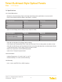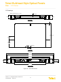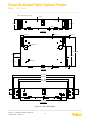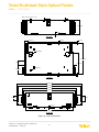
1
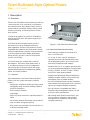
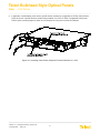
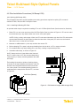
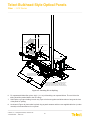
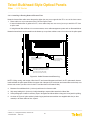
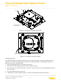
Telect Bulkhead-Style Optical Panels
Fiber :: LCX Series
User Manual
Applys to : LCX Series
© Telect, Inc., All Rights Reserved, 126254-5 A0
1.509.926.6000 :: telect.com
Telect Bulkhead-Style Optical Panels
Fiber :: LCX Series
Table of Contents
1. Description������������������������������������������������������������������������������������������������������������������������1
1.1 Overview�������������������������������������������������������������������������������������������������������������������������1
1.1.1 Features������������������������������������������������������������������������������������������������������������������1
1.1.2 Capacities/Capabilities/Suitability��������������������������������������������������������������������������� 1
1.1.3 Benefits�������������������������������������������������������������������������������������������������������������������2
1.1.4 Applications�������������������������������������������������������������������������������������������������������������2
1.2 LCX Fiber Panels������������������������������������������������������������������������������������������������������������2
1.2.1 General Information������������������������������������������������������������������������������������������������2
1.2.2 LCX Fiber Splice Panels�����������������������������������������������������������������������������������������4
1.2.2.1 LCX 1RU Fiber Splice Trays - 24-Splice Capability��������������������������������������������� 4
1.2.2.2 LCX 2RU, 3RU, & 4RU Fiber Splice Trays���������������������������������������������������������� 5
1.2.3 LCX Fiber Patch Panels������������������������������������������������������������������������������������������8
1.3 Special Function Modules���������������������������������������������������������������������������������������������10
1.4 Specifications���������������������������������������������������������������������������������������������������������������� 11
1.4.1.Overall Dimensions����������������������������������������������������������������������������������������������� 11
1.4.2 Environment���������������������������������������������������������������������������������������������������������� 11
1.4.3 Mounting��������������������������������������������������������������������������������������������������������������� 11
1.4.4 Cable Compatibility�����������������������������������������������������������������������������������������������12
1.4.5 Adapter Choices����������������������������������������������������������������������������������������������������12
1.4.6 Optical Protections������������������������������������������������������������������������������������������������12
1.4.7 Optical Performance���������������������������������������������������������������������������������������������12
1.4.8 Compliance�����������������������������������������������������������������������������������������������������������12
1.4.9 Certification�����������������������������������������������������������������������������������������������������������12
1.5 Drawings�����������������������������������������������������������������������������������������������������������������������13
2. Applications���������������������������������������������������������������������������������������������������������������������19
2.1 Interconnecting IFC to Network Elements�������������������������������������������������������������������� 19
2.2 Interconnecting Network Elements������������������������������������������������������������������������������� 19
2.3 Cross-Connecting Network Elements��������������������������������������������������������������������������� 20
2.4 Cross-Connecting Combinations����������������������������������������������������������������������������������20
2.5 Interconnecting & Cross-Connecting Along with Special Function Modules���������������� 22
3. Panel Installation������������������������������������������������������������������������������������������������������������25
3.1 Installation Considerations��������������������������������������������������������������������������������������������25
3.1.1 Location & Space��������������������������������������������������������������������������������������������������25
3.1.2 Tools & Equipment������������������������������������������������������������������������������������������������25
3.1.3 Inspection��������������������������������������������������������������������������������������������������������������25
3.2 Panel Installation Procedure (All Except 1RU)������������������������������������������������������������� 26
3.3 Panel Installation Procedure (1RU)������������������������������������������������������������������������������ 30
4. Fiber Installation�������������������������������������������������������������������������������������������������������������33
4.1 Fiber Installation Overview�������������������������������������������������������������������������������������������33
4.2 Fiber Installation Procedures (All Except 1RU)������������������������������������������������������������ 34
4.2.1 Splicing (All Except 1RU)��������������������������������������������������������������������������������������34
4.2.1.1 Installing & Routing IFC Fiber���������������������������������������������������������������������������� 34
4.2.1.2 Installing & Routing Network Element Fiber������������������������������������������������������ 36
4.2.1.3 Splicing��������������������������������������������������������������������������������������������������������������37
© Telect, Inc., All Rights Reserved, 126254-5 A0
1.509.926.6000 :: telect.com
ii
Telect Bulkhead-Style Optical Panels
Fiber :: LCX Series
4.2.2 Patching (All Except 1RU)������������������������������������������������������������������������������������38
4.3 Fiber Installation Procedures (1RU)����������������������������������������������������������������������������� 38
4.3.1 Splicing (1RU)�������������������������������������������������������������������������������������������������������38
4.3.1.1 Installing & Routing IFC Fiber���������������������������������������������������������������������������� 38
4.3.1.2 Installing & Routing Network Element Fiber������������������������������������������������������ 40
4.3.1.3 Splicing��������������������������������������������������������������������������������������������������������������40
4.2.2 Patching (1RU)�����������������������������������������������������������������������������������������������������41
5. Service����������������������������������������������������������������������������������������������������������������������������43
5.1 Owner Maintenance������������������������������������������������������������������������������������������������������43
5.2 Technical Support���������������������������������������������������������������������������������������������������������43
5.3 In-Warranty Service������������������������������������������������������������������������������������������������������43
5.4 Out of Warranty Service������������������������������������������������������������������������������������������������43
5.5 Repacking for Shipment�����������������������������������������������������������������������������������������������44
5.6 High Insertion Loss and the Importance of Cleaning Connectors & Adapters�������������� 44
6. Accessories���������������������������������������������������������������������������������������������������������������������45
6.1 Accessories and Replacement Parts���������������������������������������������������������������������������� 45
List of Figures
Figure 1 - LCX Fiber Patch Panel (4RU)������������������������������������������������������������������������������ 1
Figure 2 - LCX Fiber Panels (Common Physical Features of 2RU Through 4RU)��������������� 3
Figure 3 - LCX 1RU Fiber Panel�������������������������������������������������������������������������������������������3
Figure 4 - 1RU Fiber Splice Tray������������������������������������������������������������������������������������������4
Figure 5 - 1RU Splice Tray (Right Corner Tray)�������������������������������������������������������������������� 4
Figure 6 - 1RU Splice Tray - Fiber Routing��������������������������������������������������������������������������� 5
Figure 7 - 1RU Cable Clamp Fits 12 to 24 Fiber IFC������������������������������������������������������������ 5
Figure 8 - LCX Splice Panel, 2RU — 24 Termination Capacity�������������������������������������������� 6
Figure 9 - LCX Splice Panel, 3RU — 48 Termination Capacity�������������������������������������������� 6
Figure 10 - LCX Splice Panel, 4RU — 72 to 96 Termination Capacity��������������������������������� 6
Figure 11 - Splice Tray (Right Corner View)������������������������������������������������������������������������� 7
Figure 12 - Splice Tray (Fiber Routing)��������������������������������������������������������������������������������� 7
Figure 13 - Optional Cable Clamp Fits All Sizes of IFC�������������������������������������������������������� 8
Figure 14 - LCX Patch Panel, 1RU — 12 Termination���������������������������������������������������������� 8
Figure 15 - LCX Patch Panel, 2RU — 24 Termination���������������������������������������������������������� 9
Figure 16 - LCX Patch Panel, 3RU — 48 Termination���������������������������������������������������������� 9
Figure 17 - LCX Patch Panel, 4RU — 72, 96, or 144 Termination��������������������������������������� 9
Figure 18 - Patch Plates�����������������������������������������������������������������������������������������������������10
Figure 19 - WDM & Splitter Modules����������������������������������������������������������������������������������10
Figure 20 - 1RU LCX Chassis��������������������������������������������������������������������������������������������13
Figure 21 - 2RU LCX Chassis��������������������������������������������������������������������������������������������14
Figure 22 - 3RU LCX Chassis��������������������������������������������������������������������������������������������15
Figure 23 - 4RU LCX Chassis��������������������������������������������������������������������������������������������16
Figure 24 - Pull-Out & Swing-Out Clearances�������������������������������������������������������������������� 17
Figure 25 - Interconnecting/Splicing Facility Cable to Network Elements�������������������������� 19
Figure 26 - Interconnecting Network Elements in a LCX Fiber Patch Panel���������������������� 19
Figure 27 - Cross-Connecting Network Elements�������������������������������������������������������������� 20
© Telect, Inc., All Rights Reserved, 126254-5 A0
1.509.926.6000 :: telect.com
iii
Telect Bulkhead-Style Optical Panels
Fiber :: LCX Series
Figure 28 - Cross-Connecting IFC to Network Elements���������������������������������������������������� 21
Figure 29 - Interconnecting/Cross-Connecting Along with WDM/Splitter Modules������������� 23
Figure 30 - Removing Knockouts & Installing Plastic Grommets��������������������������������������� 26
Figure 31 - Installing a Standard Split Arc�������������������������������������������������������������������������� 27
Figure 32 - Installing a Standard Isolation Hook Kit������������������������������������������������������������ 27
Figure 33 - Installing An Optional Arc Kit���������������������������������������������������������������������������� 27
Figure 34 - Mounting LCX Panel to Rack��������������������������������������������������������������������������� 28
Figure 35 - Installing Adapter Pack & Special Function Modules��������������������������������������� 28
Figure 36 - Inserting Cabling Rings������������������������������������������������������������������������������������29
Figure 37 - Cable Restraint Layout (Top View of Chassis Bottom)������������������������������������� 29
Figure 38 - Mounting 1RU LCX Panel to Rack������������������������������������������������������������������� 30
Figure 39 - Mounting 1RU LCX Combo Panels to Rack����������������������������������������������������� 30
Figure 40 - Installing Patch Plates & Special Function Modules in a 1RU������������������������� 31
Figure 41 - IFC Breakout Length (2RU through 4RU)�������������������������������������������������������� 34
Figure 42 - IFC Clamp��������������������������������������������������������������������������������������������������������34
Figure 43 - Installing IFC for Splicing����������������������������������������������������������������������������������35
Figure 44 - Cable Placement and Securing������������������������������������������������������������������������ 36
Figure 45 - Splice Tray (Right Corner View)����������������������������������������������������������������������� 37
Figure 46 - Splice Tray (Fiber Routing)������������������������������������������������������������������������������� 37
Figure 47 - Installing Interconnects or Cross-Connects in an LCX Fiber Patch Panel������� 38
Figure 48 - IFC Breakout Length (1RU)������������������������������������������������������������������������������ 39
Figure 49 - IFC Breakout Length (1RU)������������������������������������������������������������������������������ 39
Figure 50 - Cable Routing���������������������������������������������������������������������������������������������������40
Figure 51 - 1RU Splice Tray (Right Corner Tray)���������������������������������������������������������������� 41
Figure 52 - 1RU Splice Tray (Fiber Routing)���������������������������������������������������������������������� 41
Figure 53 - Cleaning the Adapter����������������������������������������������������������������������������������������44
© Telect, Inc., All Rights Reserved, 126254-5 A0
1.509.926.6000 :: telect.com
iv
Telect Bulkhead-Style Optical Panels
Fiber :: LCX Series
1. Description
1.1 Overview
Telect’s LCX Patch/Splice Panel Systems provide inter
-connectivity and cross-connectivity of riser/plenum
and network element fiber cabling. Panels provide a
central location for patching, splicing, testing, trouble
shooting, monitoring, and restoring service to fiber
optic systems.
LCX panels fit standard 19- and 23-in. (EIA/WECO
spacing) and ETSI racks. 4RU panels support up to
144 terminations.
LCX Patch Panels and Splice Panels provide a
total solution as well as standalone splice and
patch capabilities. All Telect LCX panels are system
compatible with standard LGX® style panels, thereby
serving as replacements or add-ons in system solutions
of other manufacture. Patch adapter terminations
include SC/UPC and APC, and FC/UPC and APC,
LC/UPC, and ST/UPC.
Figure 1 - LCX Fiber Patch Panel (4RU)
1.1.2 Capacities/Capabilities/Suitability
• LCX panels are available for universal 19-in.,
23-in., and ETSI racks.
• 12, 24, 48, 72, 96 or 144 (LC) termination
capacities per panel (1RU through 4RU) using
site installed patch plates. Up to 144 per panel
with factory-installed discrete adapters.
LCX Patch Panels are available with or without
fiber adapters. Telect offers patch plates with 6, 8,
or 12 adapters per plate for on-site configuration.
1RU through 4RU LCX Patch Panels also accept
standard Wavelength Division Multiplexing (WDM),
splitter, and monitor modules.
• Standard-size 6, 8, or 12 adapters per patch plate
for on-site patch panel adaptation of empty panels.
• SC/UPC, SC/APC, FC/UPC, FC/APC, LC/UPC,
and ST/UPC patch plates available.
1.1.1 Features
• Standard-size Wavelength Division Multiplexing
(WDM) and splitter modules can be used along
with adapter packs for added flexibility.
Telect manufactures LCX Patch Panels and Splice
Panels to suit any system architecture. Features
include —
• Designed for compliance (fiber bend radius control,
flammability safety, structural reliability). NEBS 3
and ETSI certification.
• All LCX Patch/Splice Panels are fully compatible
with standard LGX® style panels for IFC entrance,
splicing, and network patching architecture.
• All LCX panels are compatible with Telect’s
WaveTrax cable management systems, as well
as those of other manufacturers.
• Zone 4 Seismic reliability.
• Light weight.
• 2RU through 4RU models include slip-on, split
arcs for patch cord entrance; optional cable
management kits available to suit operating
company preferences.
• Splice tray easily removed for rapid termination of
cable.
• No cassette required. Removable trays provide for
easy and direct storage and splicing.
• Easy access via removable front and rear doors or
bi-directional sliding drawer.
© Telect, Inc., All Rights Reserved, 126254-5 A0
1.509.926.6000 :: telect.com
1
Telect Bulkhead-Style Optical Panels
Fiber :: LCX Series
1.1.3 Benefits
Telect’s LCX Splice/Patch Panels are ideal for central office, head-end and wiring centers. Benefits include:
• Low cost
• High Fiber Density
• Versatility.
• Easy Installation.
• Compatibility.
• Simple, straight-forward cable management, access, circuit identification and isolation.
• Easy access to riser/network/patch cord connections.
1.1.4 Applications
• CATV
• MTSO
• Outside plant
• Central Office
• Optical distribution/cross-connect
1.2 LCX Fiber Panels
1.2.1 General Information
Telect manufactures LCX Fiber Splice Panels and LCX Fiber Patch Panels of various densities to suit company
-wide fiber splice, patching, and routing requirements.
All LCX Fiber Panels are white or black metal chassis in various sizes (1RU through 4RU) accommodating
various fiber densities. All panels (2RU - 4RU) come equipped with front and rear metal doors. All include cable
entry/exit points near the panels’ four corners:
• 2RU through 4RU models vary in density from 24 to 144 fiber terminations. All have spring-hinged removable
front and rear doors, as shown in the following illustration. Knock-out holes at the top and bottom of the panel
allow for routing from splice panels to patch panels (and between patch panels) vertically within the rack. Hole
pattern and positions are compatible with panels offered by other manufacturers, allowing expansion and
replacement of those systems using Telect’s low-cost LCX panels.
• Interconnection and cross-connection cabling from above or below enter at the two front corners of each
Telect LCX panel via isolation hooks and/or radius control arcs installed on-site to suit the application and
entry/exit direction. Eight split arcs and fourteen snap-in cable rings are standard with each panel. Telect also
offers two optional kits to satisfy cable management practices requiring multiple arcs or guide posts to separate
and isolate groups of fiber cables.
© Telect, Inc., All Rights Reserved, 126254-5 A0
1.509.926.6000 :: telect.com
2
Telect Bulkhead-Style Optical Panels
Fiber :: LCX Series
Figure 2 - LCX Fiber Panels (Common Physical Features of 2RU Through 4RU Panels)
1RU models have densities up to 24 fiber terminations. Instead of front and rear doors, 1RUs have a removable
sliding drawer that can be extended at the front or rear of the chassis to maximize access to fiber connections.
Pivoting arcs at corner entries and exits provide cable management. Entry and exit positions are compatible with
entries and exits of other Telect LCX panels and those of other manufacture.
Brackets (2) for Either
19-in. or 23-in. Rack
Twist Latch
Pivoting Arcs (8) Maintain
Bend Radius
Double-Hung Drawer Pulls Out
from Front or Rear
Figure 3 - LCX 1RU Fiber Panel
© Telect, Inc., All Rights Reserved, 126254-5 A0
1.509.926.6000 :: telect.com
3
Telect Bulkhead-Style Optical Panels
Fiber :: LCX Series
1.2.2 LCX Fiber Splice Panels
Telect offers four sizes of LCX Fiber Splice Panels (1RU through 4RU) to accommodate up to 144 splices.
Each removable splice tray holds up to 24 splices along with 1½ m of fiber cable storage:
• For a 1RU splice tray, all fiber (subunit, cable, and strands) is stored on the tray.
• For a 2RU, 3RU or 4RU splice tray, all subunit and interconnection cable storage is below the trays.
Trays easily slip free of the panels to allow splicing. Storage spools or arcs, along with splice holders, are mounted
directly on the tray, eliminating the need for special splice cassettes.
1.2.2.1 LCX 1RU Fiber Splice Trays - 24-Splice Capability
Figure 4 - 1RU Fiber Splice Tray
LCX 1RU Fiber Splice Trays use sets of pivoting arcs for routing and storing both fiber subunits and
interconnection cable.
Arcs (14)
Splice Cover
Each of Two Splice Holders
Holds 12 Splices
Figure 5 - 1RU Splice Tray (Right Corner Tray)
© Telect, Inc., All Rights Reserved, 126254-5 A0
1.509.926.6000 :: telect.com
4
Telect Bulkhead-Style Optical Panels
Fiber :: LCX Series
From
IFC
Tie-Down for Cable Ties*
Tie-Down for Cable Ties*
To Network
Elements
* Use either lacing or cable ties to secure cable subunit, flexible tubing, and/or sheathing.
Figure 6 - 1RU Splice Tray - Fiber Routing
IFC stranded cable from the splice vault is secured at either rear corner of the LCX Splice Panel by an optional
cable clamp. (A single clamp comes with two rubber bushings to fit either a 12- or 24-fiber IFC riser/plenum
cable.) The following illustration shows a clamp holding an IFC cable installed on the rear rack flange near the
entry/exit of an LCX 1RU Splice Panel. The interconnection cables enter the tray at one of the other corners of
the splice tray.
2 4 -F ibe r IF C
N e tw o rk C a ble
Leave s ufficient
s la c k to a llo w dra w e r
to open.
C a ble C la m p
Figure 7 - 1RU Cable Clamp Fits 12 to 24 Fiber IFC
1.2.2.2 LCX 2RU, 3RU, & 4RU Fiber Splice Trays
The following Figures show termination capacities of LCX 2RU, 3RU,and 4RU Fiber Splice Panels. A 144-splice,
4RU LCX panel accommodating 6 splice trays is available but not pictured.
• 24-splice, 2RU LCX panel accommodates 1 splice tray
• 48-splice, 3RU LCX panel accommodates 2 splice trays
• 72-splice, 4RU LCX panel accommodates 3 splice trays
• 96-splice, 4RU LCX panel accommodates 4 splice trays
© Telect, Inc., All Rights Reserved, 126254-5 A0
1.509.926.6000 :: telect.com
5
Telect Bulkhead-Style Optical Panels
Fiber :: LCX Series
2RU, 3RU, and 4RU Fiber Splice Trays use storage spools to route and store stranded fiber.
Figure 8 - LCX Splice Panel, 2RU — 24 Termination Capacity
Figure 9 - LCX Splice Panel, 3RU — 48 Termination Capacity
Figure 10 - LCX Splice Panel, 4RU — 72 to 96 Termination Capacity
© Telect, Inc., All Rights Reserved, 126254-5 A0
1.509.926.6000 :: telect.com
6
Telect Bulkhead-Style Optical Panels
Fiber :: LCX Series
S plice C over
S p o ols (2)
T ie-D ow n Locations
for Incom ing/O utgoing C able*
E ach of tw o splice holders
h olds 1 1 2 splices.
*Use either lacing or cable ties to secure cable
subunit, flexible tubing, and/or sheathing
Figure 11 - Splice Tray (Right Corner View)
Stranded fiber from IFC is wound
around one of the spools...
Pigtail from NE is wound around
the other spool.*
From IFC
Tie-Down Locations for Cable Ties
To Network Elements
* Strands are always routed clockwise on the left spool and counter-clockwise on the right spool.
Figure 12 - Splice Tray (Fiber Routing)
IFC stranded cable from the splice vault is secured at either rear corner of the LCX Splice Panel by an optional
cable clamp. (A single clamp fits all sizes of IFC riser and plenum cable.) Figure 13 on the following page shows
a clamp holding a 96-strand IFC cable installed at the left rear corner of an LCX Splice Panel. Cable rings in the
rear portion of the panel lead the IFC tubes to one of the front corners of the splice trays. The interconnection
cables enter the tray at the other front corner of the 2RU/3RU/4RU splice tray.
© Telect, Inc., All Rights Reserved, 126254-5 A0
1.509.926.6000 :: telect.com
7
Telect Bulkhead-Style Optical Panels
Fiber :: LCX Series
96-Fiber IFC
KIT-CMRHOOK
Cable Clamp
Figure 13 - Optional Cable Clamp Fits All Sizes of IFC
1.2.3 LCX Fiber Patch Panels
LCX Fiber Patch Panels come in six termination capacities and can be loaded with various patch plates. Refer to
Figures 14 - 17.
In addition to patch panels with or without installed patch plates, Telect offers a special factory-configured 4RU
patch panel with 144 discrete SC/UPC adapters.
All panels can accommodate SC/UPC, SC/APC, FC/UPC, FC/APC, LC/UPC, or ST/UPC patch plates. Patch
plates simply snap into the chassis’ bulkhead:
• SC/UPC, SC/APC, FC/UPC, FC/APC and ST/UPC are available in patch plates with 6 or 8 adapters
• LC/UPC is available in patch plates with 12 adapters
All adapters include dust covers. Like the chassis, most patch plates are available in white or black. Refer to Figure 18.
Figure 14 - LCX Patch Panel, 1RU — 12 Termination
© Telect, Inc., All Rights Reserved, 126254-5 A0
1.509.926.6000 :: telect.com
8
Telect Bulkhead-Style Optical Panels
Fiber :: LCX Series
Figure 15 - LCX Patch Panel, 2RU — 24 Termination
Figure 16 - LCX Patch Panel, 3RU — 48 Termination
Figure 17 - LCX Patch Panel, 4RU — 72, 96, or 144 Termination
© Telect, Inc., All Rights Reserved, 126254-5 A0
1.509.926.6000 :: telect.com
9
Telect Bulkhead-Style Optical Panels
Fiber :: LCX Series
6-Adapter Patch Plate (SC, FC, ST)
8-Adapter Patch Plate (SC, FC, ST)
12-Adapter Patch Plate (LC Only)
Figure 18 - Patch Plates
1.3 Special Function Modules
Empty LCX Fiber Patch Panels can be configured on-site with adapter packs and special function modules.
Telect offers a full line of standard-size Wavelength Division Multiplexing (WDM) modules and splitter modules
that can be used in place of adapter packs. Some special-function Telect modules are illustrated below. Call
Telect at 1-509-926-6000. See Telect.com for detailed information.
Figure 19 - WDM & Splitter Modules
© Telect, Inc., All Rights Reserved, 126254-5 A0
1.509.926.6000 :: telect.com
10
Telect Bulkhead-Style Optical Panels
Fiber :: LCX Series
1.4 Specifications
1.4.1.Overall Dimensions
• Dimensions: See the drawings (Figure 20 through 24) following these specifications for access and fit.
• Patch Chassis Weight (without adapters, patch plates, or cabling):
Patch Assemblies
Weight (lb)
Weight (kg)
2RU
6.0
2.72
1RU
3RU
4RU
5.0
2.27
7.0
3.18
8.0
3.63
• Splice Chassis Weight (without cabling or trays, except as noted):
Splice Assemblies
Weight (kg)
Weight (lb)
2RU (with one splice tray)
6.0
2.72
1RU (with one splice tray)
3RU
4RU
5.0
2.27
7.0
3.18
8.0
3.63
• 2RU, 3RU, & 4RU Splice Tray Weight (without cabling):
• 1RU Chassis and Tray Material & Finish: 0.060 cold-rolled steel. Finish is either powder-coat white or black.
• 2RU, 3RU, & 4RU Chassis and Tray Material & Finish: Cold-rolled 0.080 aluminium for all but bottom. Bottom
is .060 coldrolled steel. Finish is either powder-coat white or black.
• Black Tray Components: 94 V0 PC/ABS black plastic
• Splice Cover: Transparent polycarbonate
1.4.2 Environment
• Ambient Temperature: -5°C to 55°C (23°F to 131°F)
• Relative Humidity: 0% to 90% and noncondensing
1.4.3 Mounting
• 19-in. or 23-in. with ETSI, EIA, or WECO spacing.
© Telect, Inc., All Rights Reserved, 126254-5 A0
1.509.926.6000 :: telect.com
11
Telect Bulkhead-Style Optical Panels
Fiber :: LCX Series
1.4.4 Cable Compatibility
• 250 μm OSP
• 900 μm IFC
• 1.75 mm, 2 mm, and 3 mm patch cords and jumpers (Simplex or Duplex)
1.4.5 Adapter Choices
• SC/UPC and APC in 6- and 8-position patch plates
• FC/UPC and APC in 6- and 8-position patch plates
• LC/UPC in 12-position patch plates only
• ST/UPC in 6- and 8-position patch plates only
1.4.6 Optical Protections
• Bend Radius: >30 mm throughout for all cable routing
• Eye Protection: All adapters have factory-installed dust covers.
1.4.7 Optical Performance
LCX will not influence signal timing or jitter.
1.4.8 Compliance
NEBS, ETSI, Zone 4 seismic reliability
1.4.9 Certification
UL 60950, CE EN 60950, Bellcore GR-63-CORE, Bellcore GR-1089-CORE, ETSI EN 300 019-2-(1,2,3)
© Telect, Inc., All Rights Reserved, 126254-5 A0
1.509.926.6000 :: telect.com
12
Telect Bulkhead-Style Optical Panels
Fiber :: LCX Series
1.5 Drawings
NOTE: Dimensions are in in. (mm).
0.12 [2.9]
1.64 [41.6]
1.73 [44.0]
REAR VIEW
(ROTATED)
0.06 [1.4]
11.00 [279.4]
1.50 [38.1]
3.55 [90.2]
0.30 [7.6]
TOP VIEW
23.04 [585.3]
22.35 [567.8]
19.04 [483.7]
18.36 [466.3]
1.25 [31.7]
1.00 [25.4]
15.06 [382.4]
FRONT VIEW
Figure 20 - 1RU LCX Chassis
© Telect, Inc., All Rights Reserved, 126254-5 A0
1.509.926.6000 :: telect.com
13
Telect Bulkhead-Style Optical Panels
Fiber :: LCX Series
NOTE: Dimensions are in in. (mm).
0.10 [2.5]
0.18 [4.7]
3.26 [82.8]
3.45 [87.6]
0.19 [4.7]
REAR VIEW
(ROTATED)
0.24 [6.2]
0.99 [25.3]
0.12 [2.9]
Ø1.50 [Ø38.1]
10.74 [272.9]
1.50 [38.1]
3.21 [81.6]
7.38 [187.4]
Ø0.26 [Ø6.5]
0.12 [3.1]
0.24 [6.2]
TOP VIEW
23.00 [584.2]
22.31 [566.7]
19.00 [482.6]
18.28 [464.3]
1.76 [44.6]
2.01 [51.0]
0.19 [4.7]
0.19 [4.8]
17.03 [432.5]
FRONT VIEW
Figure 21 - 2RU LCX Chassis
© Telect, Inc., All Rights Reserved, 126254-5 A0
1.509.926.6000 :: telect.com
14
Telect Bulkhead-Style Optical Panels
Fiber :: LCX Series
NOTE: Dimensions are in in. (mm).
0.09 [2.4]
0.18 [4.7]
4.92 [124.8]
0.19 [4.7]
REAR VIEW
(ROTATED)
0.24 [6.2]
0.99 [25.2]
0.12 [2.9]
Ø1.50 [Ø38.1]
10.75 [273.0]
1.50 [38.1]
3.21 [81.6]
7.38 [187.5]
Ø0.26 [Ø6.5]
0.12 [2.9]
0.24 [6.2]
TOP VIEW
23.00 [584.2]
22.31 [566.7]
19.00 [482.6]
18.28 [464.3]
1.76 [44.6]
2.01 [51.0]
0.19 [4.7]
0.19 [4.8]
17.03 [432.5]
FRONT VIEW
Figure 22 - 3RU LCX Chassis
© Telect, Inc., All Rights Reserved, 126254-5 A0
1.509.926.6000 :: telect.com
15
Telect Bulkhead-Style Optical Panels
Fiber :: LCX Series
NOTE: Dimensions are in in. (mm).
0.09 [2.4]
0.19 [4.7]
6.72 [170.6]
0.17 [4.3]
REAR VIEW
(ROTATED)
1.29 [32.9]
0.24 [6.2]
0.12 [2.9]
Ø1.50 [Ø38.1]
10.72 [272.4]
7.36 [186.9]
Ø0.26 [Ø6.5]
3.21 [81.6]
0.12 [2.9]
0.24 [6.2]
TOP VIEW
23.00 [584.3]
22.31 [566.8]
19.01 [482.8]
18.32 [465.3]
3.00 [76.1]
1.76 [44.6]
0.19 [4.7]
0.19 [4.8]
17.03 [432.5]
FRONT VIEW
Figure 23 - 4RU LCX Chassis
© Telect, Inc., All Rights Reserved, 126254-5 A0
1.509.926.6000 :: telect.com
16
Telect Bulkhead-Style Optical Panels
Fiber :: LCX Series
R6.85 [R174.0]
R6.85 [R174.0]
4RU (Right-Side View)
R5.05 [R128.3]
R5.05 [R128.3]
3RU (Right-Side View)
REAR
FRONT
R3.39 [R86.1]
R3.39 [R86.2]
2RU (Right-Side View)
5.69 [144.6]
4.73 [120.2]
1RU (Top View)
Figure 24 - Pull-Out & Swing-Out Clearances
© Telect, Inc., All Rights Reserved, 126254-5 A0
1.509.926.6000 :: telect.com
17
Telect Bulkhead-Style Optical Panels
Fiber :: LCX Series
This page intentionally left blank.
© Telect, Inc., All Rights Reserved, 126254-5 A0
1.509.926.6000 :: telect.com
18
Telect Bulkhead-Style Optical Panels
Fiber :: LCX Series
2. Applications
2.1 Interconnecting IFC to Network Elements
Figure 25 shows a simple interconnection scheme where OSP is spliced at a vault to IFC plenum or a riser cable,
which is then spliced at an LCX Fiber Splice Panel to the network elements.
NOTE: Stranded or ribbon fiber should always enter or leave LCX panels in tied-down tubes, sheathed cable, or
flex tubing.
Splice Vault
LCX Fiber Splice Panel
Subunit Tube
OSP
IFC
900µm
Sheathed
Cable
2 - 3 mm
To Network Elements
Figure 25 - Interconnecting/Splicing Facility Cable to Network Elements
2.2 Interconnecting Network Elements
In Figure 26, fiber from one set of network elements is interconnected to a second set.
LCX Fiber Patch Panel
To/From NE1s
Use rings to help guide
and organize strands,
ribbon, tubing, and
cable into smooth, neat
groups.
Cables and tubes must be secured to tie
downs using supplied or other restraint
on entering and leaving panel
2 mm, 3 mm , or
Multifiber Sheathed
Cable
Tie Down for Restraint
Velco-Style Retrains
are Supplied
From/To NE2s
Figure 26 - Interconnecting Network Elements in a LCX Fiber Patch Panel
© Telect, Inc., All Rights Reserved, 126254-5 A0
1.509.926.6000 :: telect.com
19
Telect Bulkhead-Style Optical Panels
Fiber :: LCX Series
2.3 Cross-Connecting Network Elements
In a variation of “Interconnecting Network Elements”, NE1s and NE2s are connected to the rear of two LCX Fiber
Patch Panels with the fronts reserved for patch cords to cross-connect the two.
Figure 27 shows a stylized version of this application.
NE1 Pigtails
Network
Element 1
NE2 Pigtails
I
O
Rear
Front
Front
Rear
Patch Cords
LCX Fiber Patch Panel
Figure 27 - Cross-Connecting Network Elements
2.4 Cross-Connecting Combinations
LCX Fiber Splice and Patch Panels can be used in combination to cross-connect IFC to network elements.
Figure 28 shows a 48-fiber LCX Combination Panel (a 48-fiber LCX Splice Panel bolted to a 48-fiber LCX Patch
Panel). After the incoming IFC is spliced, the fiber strands are passed through the 1½ in. (38.1 mm) diameter
hole in the top of the splice shelf to the patch shelf. Notice that flexible edge protectors are used to protect the
unsheathed fiber strand passing through holes to an upper panel.
NOTE: If you create your own combination LCX Splice and Patch Panel onsite, remember to remove knockout
plugs at the top and bottom of LCX panels before installing panels in racks. (Knockouts can be removed and
flexible edge protectors can be installed around edge of holes after panels are racked; however, it is easier
before panels are racked.) Avoid removing the knockouts on the top of the top-most and bottom of the bottom
most LCX panels. The knockout plugs also provide fire abatement.
© Telect, Inc., All Rights Reserved, 126254-5 A0
1.509.926.6000 :: telect.com
20
Telect Bulkhead-Style Optical Panels
Fiber :: LCX Series
To NE s
Sheathed Cable
or Patch Cords
4 8-Fib er IFC
Use flex tubing or other
sheathing wherever possible
to protect unsheathed fiber
strands and ribbon.
Flexible edge protectors
installed around access
hole edges of 3RU and
4RU combo
Subunit
Dimples with bolt holes
Holes allow panels to be
bolted together and handled
as a unit*
Tie Downs. Use Velcro-style strips,
(supplied) or other restraint
wherever cable or tubing enters
or exits panels or trays. Never
restrain unprotected fiber (individual
strands or ribbon); always place strands
or ribbon in protective tubing before restraining.
Leave fire-abatement knockouts in
place at the top of the top-most LCX
panel and at the bottom of the
lower-most panel.
*Combination LCX panels (patch panel on top; splice panel on bottom) are bolted together at the factory. Combination 3RU and 4RU panels are bolted
top to bottom as shown here. Combination 1RU panels are bolted together by a special rack bracket.
Figure 28 - Cross-Connecting IFC to Network Elements
© Telect, Inc., All Rights Reserved, 126254-5 A0
1.509.926.6000 :: telect.com
21
Telect Bulkhead-Style Optical Panels
Fiber :: LCX Series
2.5 Interconnecting & Cross-Connecting Along with Special Function Modules
Wavelength Division Multiplexing (WDM) and splitter modules can be used in LCX panels.
Figure 29 shows one way a 48-fiber IFC is spliced and then interconnected via splitters/WDMs to network elements.
Notice that three, 3RU LCX Configurable Panels with dual, 1-to-3 splitters (or dual WDMs) are required for splitting/de-multiplexing the 48 incoming fiber signals.
Dedicated LCX Patch Panels can be used to interconnect/cross-connect the split/de-multiplexed signals with the
network elements. In such case,
• Splitting 48 signals three ways requires a 4RU LCX Patch Panel with 144 adapters
• De-multiplexing 48 signals into two wavelengths requires a 4RU LCX Patch Panel with 96 adapters.
© Telect, Inc., All Rights Reserved, 126254-5 A0
1.509.926.6000 :: telect.com
22
Telect Bulkhead-Style Optical Panels
Fiber :: LCX Series
A single, factory-configured 4RU Fiber
Patch Panel can be used for centralized
patching of outputs from the splitters.
144-Fiber, 4RU LCX Patch Panel
To 144 NEs
Three, 3RU LCX Configurable Patch Panels
with eight, 1-to-3 dual splitters can be used
to terminate spliced strands from a
single 48-fiber LCX Fiber Splice Panel.
48-Fiber IFC
One of Three, 3RU LCX Configurable Patch Panels
48-Fiber, 3RU LCX Fiber Splice Panel
Figure 29 - Interconnecting/Cross-Connecting Along with WDM/Splitter Modules
© Telect, Inc., All Rights Reserved, 126254-5 A0
1.509.926.6000 :: telect.com
23
Telect Bulkhead-Style Optical Panels
Fiber :: LCX Series
This page intentionally left blank.
© Telect, Inc., All Rights Reserved, 126254-5 A0
1.509.926.6000 :: telect.com
24
Telect Bulkhead-Style Optical Panels
Fiber :: LCX Series
3. Panel Installation
3.1 Installation Considerations
!
WARNING
WARNING! Fiber cables transmit invisible infrared light. To avoid eye damage or blindness, never look
directly into fibers or connectors.
ADVERTENCIA! Los cables de fibra transmiten luz láser o infrarroja invisible. Para evitar lesiones
oculares o ceguera, nunca mire directamente a las fibras o conectores.
AVERTISSMENT! Les câbles à fibres transmettent un rayon laser ou une lumière infrarouge invisible.
Pour éviter toute lésion occulaire ou cécité, ne regardez jamais directement dans les fibres ou dans les
connecteurs.
!
ALERT
ALERT! This product must be installed and maintained only by qualified technicians.
ALERT! These instructions presume you have verified that the Telect equipment being installed is
compatible with the rest of the system, including power, ground, circuit protection, signal characteristics,
equipment from other vendors, and local codes or ordinances.
3.1.1 Location & Space
LCX Fiber Panels adapt to standard 19 in., 23 in., or ETSI racks with WECO, EIA, or ETSI spacing and nominal
3¼-in. extensions beyond the front rack flange.
Plan the input/output, upward/downward (cable feed) layout of each panel and its position in the rack before
beginning LCX panel installation. If you plan to pass fiber strands, cable, and/or tubing through the knocked-out
holes in the tops and bottoms of the panels, the panels should be mounted in contiguous vertical rack spaces.
3.1.2 Tools & Equipment
No special tools required.
3.1.3 Inspection
Please read and understand all instructions before starting installation. If you have questions, contact Telect
Technical Support at [email protected] or call 1.509.926.6000.
When you receive the equipment, carefully unpack it and compare it to the packaging list. Please report any
defective or missing parts to Telect at [email protected] or call 1.509.926.6000.
Telect is not liable for transit damaged. If the product is damaged, please report it to the carrier and contact
Telect Quality.
© Telect, Inc., All Rights Reserved, 126254-5 A0
1.509.926.6000 :: telect.com
25
Telect Bulkhead-Style Optical Panels
Fiber :: LCX Series
3.2 Panel Installation Procedure (All Except 1RU)
Prepare, mount, and insert modules and cable management rings in all panels in a rack before cabling any
panels in the rack.
1. If applicable, if you plan to pass fiber strands, cables, and/or tubing through the 1½ in. (38.1 mm) diameter
holes in the tops and bottoms of panels, see the notes below and then knock out the applicable fire-abatement
plugs covering these holes, as shown in Figure 30. Install flexible edge protectors (or a standard grommet for
1½ in. holes) in place of plugs.
NOTES:
• Avoid removing fire-abatement plugs on the top of the top most and bottom of the bottom most panel.
• Plugs can be knocked out when panels are in place on the rack; however, plug removal is easiest before
racking panels.
2. Install standard entry/exit split arcs and/or either standard isolation hooks kits or optional entry/exit arc kits at
the front and/or rear corners of the panel.
Flexible Plastic Edge Protector
Figure 30 - Removing Knockouts & Installing Plastic Grommets
© Telect, Inc., All Rights Reserved, 126254-5 A0
1.509.926.6000 :: telect.com
26
Telect Bulkhead-Style Optical Panels
Fiber :: LCX Series
a. Installing standard split arcs - Slip the arc over
the top and/or bottom edges of the chassis at the entry/exit corners. Refer to Figure 31.
Standard Split Arcs
b. Installing an isolation hook kit - Proceed as
follows. Refer to Figure 32.
• Remove the split arc at the top and bottom of the
applicable corner entry/exit.
• Use the two Phillips head machine screws (screws
with cross recessed heads) to secure the hook
mounting plate and flat backing plate to either side
of the panel sidewall.
Figure 31 - Installing a Standard Split Arc
c. Installing an optional arc kit - Proceed as
follows.Refer to Figure 33.
• NOTE: Arcs are attached to the angle shaped
mounting bracket using a threadforming screw and
an anti-rotation boss. The bracket contains two
sets of screw and boss holes so that each arc can
be mounted with the arrow-shaped keeper flange
pointing either up or down.
• Remove the split arc at the top of the applicable
corner entry/exit. Leave the split arc at the bottom
in place, as shown in the illustration on the right.
• Use the three thread-forming Phillips head screws
(screws with cross-recessed heads) to attach the
arcs to the angle bracket. Normally, the arrow
shaped keeper flange of the top two arcs point
down and the bottom one points up. For flange
clearance, the middle and bottom arcs must use a
different set of screw and boss holes.
Figure 32 - Installing a Standard Isolation Hook Kit
Angle Bracket
• Use the two Phillips head machine screws along
with the flat backing plate to secure this arc assembly to the panel.
Arcs
Leave Bottom Split
Arc in Place
Backing Plate
Figure 33 - Installing An Optional Arc Kit
© Telect, Inc., All Rights Reserved, 126254-5 A0
1.509.926.6000 :: telect.com
27
Telect Bulkhead-Style Optical Panels
Fiber :: LCX Series
3. Mount each panel to rack using four, 12-24, thread-forming mounting screws (supplied, two per side). Refer
to Figure 34. Torque to 35 in.-lb. (4.29 N•m.). For one of the mounting screws, include a ground lug and star
washer. (Use one ground lug with #14 AWG stranded wire per chassis.)
Figure 34 - Mounting LCX Panel to Rack
NOTE: Each shelf of an LCX Fiber Splice/Patch Combination Panel must be grounded separately.
4. Install adapter packs and/or special function modules in configurable LCX Fiber Patch Panels. Figure 35
shows a 6-adapter pack being installed in a 4RU LCX Fiber Configurable Patch Panel. Push in quick-connect
plungers at both ends of faceplate to lock pack or module in bulkhead.
Plunger at Top & Bottom
of Patch Plates
Figure 35 - Installing Adapter Pack & Special Function Modules
© Telect, Inc., All Rights Reserved, 126254-5 A0
1.509.926.6000 :: telect.com
28
Telect Bulkhead-Style Optical Panels
Fiber :: LCX Series
5. Place a plastic cabling ring at each of the four corners of the chassis, as shown in Figures 36 and 37. Rings
can be added and moved around later during cabling. The rings not only serve as corrals for fiber cable but
also as guideposts. Cables can be inserted in the split rings or routed around the rings.
Plastic Cabling Rings
Figure 36 - Inserting Cabling Rings
REAR
Cable Tie-Down Positions (one at each entrance/exit)
Plastic Cabling Ring Positions (14)
FRONT
Figure 37 - Cable Restraint Layout (Top View of Chassis Bottom)
© Telect, Inc., All Rights Reserved, 126254-5 A0
1.509.926.6000 :: telect.com
29
Telect Bulkhead-Style Optical Panels
Fiber :: LCX Series
3.3 Panel Installation Procedure (1RU)
1. Mount each panel to rack using four, 12-24, thread-forming mounting screws (supplied, two per side), as
shown in Figures 38 and 39. Torque to 35 in.-lb. (4.29 N•m.) With one of the screws, include a ground lug
and star washer. (Use one ground lug and #14 AWG stranded wire per chassis.)
Figure 38 - Mounting 1RU LCX Panel to Rack
Figure 39 - Mounting 1RU LCX Combo Panels to Rack
NOTE: Each shelf of an LCX Fiber Splice/Patch Combination Panel must be grounded separately
© Telect, Inc., All Rights Reserved, 126254-5 A0
1.509.926.6000 :: telect.com
30
Telect Bulkhead-Style Optical Panels
Fiber :: LCX Series
2. If applicable, install adapter packs and/or special function modules in configurable LCX Fiber Patch Panels.
Figure 40 shows a special-function module being installed in a 1RU LCX Fiber Configurable Patch Panel.
Push in quick-connect plungers at either end of faceplate to lock pack or module in bulkhead.
Figure 40 - Installing Patch Plates & Special Function Modules in a 1RU
© Telect, Inc., All Rights Reserved, 126254-5 A0
1.509.926.6000 :: telect.com
31
Telect Bulkhead-Style Optical Panels
Fiber :: LCX Series
This page intentionally left blank.
© Telect, Inc., All Rights Reserved, 126254-5 A0
1.509.926.6000 :: telect.com
32
Telect Bulkhead-Style Optical Panels
Fiber :: LCX Series
4. Fiber Installation
4.1 Fiber Installation Overview
!
WARNING
WARNING! Fiber cables transmit invisible infrared light. To avoid eye damage or blindness, never look
directly into fibers or connectors.
ADVERTENCIA! Los cables de fibra transmiten luz láser o infrarroja invisible. Para evitar lesiones
oculares o ceguera, nunca mire directamente a las fibras o conectores.
AVERTISSMENT! Les câbles à fibres transmettent un rayon laser ou une lumière infrarouge invisible.
Pour éviter toute lésion occulaire ou cécité, ne regardez jamais directement dans les fibres ou dans
les connecteurs.
Fiber installation involves splicing, storage, and patching using LCX Splice & Patch Panels. Splicing begins with
installation of the IFC at the rear of the LCX Fiber Splice Panel. Each stranded or ribbon IFC subunit contains up
to 12 fibers and each LCX splice tray handles up to 24 splices (two subunits of fiber.)
Pairs or groups of tubes containing stranded or ribbon fiber enter the designated tray at one of the four corners
(with one of the other corners reserved for corresponding fibers originating from network elements).
• For 1RU splice trays, the tubes from the IFC or cables from the network elements are wound twice around a
set of arcs and then tied down to the floor of the tray. All fiber storage is on the tray.
• For 2RU, 3RU, and 4RU splice trays, the IFC and cables originating from the network elements are tied down
near the front of the splice tray. The unprotected strands or ribbon from the tied-down tubes and cables are
wound several times around the two spools on the tray. One of the spools is for the strands or ribbon from the
IFC and the other for the network element leads. The bottom of 2RU, 3RU, and 4RU LCX Fiber Splice Panels
is used for storing coils of excess tubes and cables.
The loose ribbon or strands are then spliced (interconnected) with the resulting splices placed in one of two,
12-place splice holders on the tray.
LCX Fiber Patch Panels can be used to either interconnect or cross-connect network elements. The panels are
typically used to interconnect IFC splices from the LCX Fiber Splice Panel to network elements, to interconnect
one system of network elements to another, as in a demarcation, or to cross-connect network elements within
the same system.
In all cases, pigtails (connected leads) from the splice panel or jumpers from the network elements are connected
to adapters on one side of the patch panel’s bulkhead. Corresponding adapters on the other side of the bulkhead
are used for interconnecting or cross-connecting complementary network element pigtails, jumpers, or patch cords.
Pigtails/jumpers/patch cords can enter the LCX Fiber Patch Panel at any of the four corners. Plastic rings or arcs
guide the pigtails/jumpers/cords to the designated adapter.
© Telect, Inc., All Rights Reserved, 126254-5 A0
1.509.926.6000 :: telect.com
33
Telect Bulkhead-Style Optical Panels
Fiber :: LCX Series
4.2 Fiber Installation Procedures (All Except 1RU)
4.2.1 Splicing (All Except 1RU)
The paragraphs that follow contain installation and routing procedures required for splicing IFC to network
elements in 2RU, 3RU,and 4RU LCX Splice Panels.
4.2.1.1 Installing & Routing IFC Fiber
An optional cable clamp is required for installing IFC to an LCX Fiber Splice Panel. (See Accessories, Section 6.)
1. Route IFC to a rear corner entrance of the LCX Fiber Splice Panel, as shown in Figure 41. IFC can be routed
from the bottom up or top down at either rear corner of the splice panel.
NOTE: Coiling, routing, and storage of fiber from IFC and network elements work best if the IFC and network
element leads exit/enter the splice panel at either the same side of the panel (IFC at the rear and network
fiber at the front) or at the two rear corners.
2. Measure an additional 83 in. (2110 mm) and then trim excess IFC.
3. Before clamping IFC to panel, strip away sheathing from this last 83 in. of IFC to expose subunits.
4. For stranded cable, strip away leading 24 in. (610 mm) of tubing to expose 900 μm fiber.
5. Assemble cable clamp, as shown in Figure 43.
An IFC clamp consists of clamp halves that fit around
the IFC. Various sizes of IFC are accommodated using
various layers (or leaves) of bushing between the cable
and clamp.
IFC
Breakout Point
The bushing kit contains a cylinder of bushing leaves,
as shown on the right. Measure the diameter of the IFC
and then remove and discard that much from the interior of the cylinder. The remaining bushing halves are
used between the clamp halves and the IFC, as shown
in Figure 43.
REAR VIEW
Solid Core (Discard)
83 in. (2110 mm) of Breakout for
Subunit Storage & Splicing
Figure 41 - IFC Breakout Length (2RU through 4RU)
Bushing Leaf
Figure 42 - IFC Clamp
© Telect, Inc., All Rights Reserved, 126254-5 A0
1.509.926.6000 :: telect.com
34
Telect Bulkhead-Style Optical Panels
Fiber :: LCX Series
C lam p H alf Bushing
C la m p P late
C lam p H alf
IFC : 144 S trands in 1 2 S ubunits
A tt a c h c la m p p la te to
lo w e r tw o h o le s in
s id ew a ll f o r b o tt o m - u p ca b le f e e d s .
C able C lam p
H ook an d loo p strap inserted
through tie-dow n to hold
sub units to floor of pa nel
S ubunit
C ab le clam ps can be p iggy-backe d to allow m ore than
one IFC at each panel entra nce . Pig gy-backing also
provides cable clearance to low er LC X S plice Pane ls.
(T he clam ps can also be secured to LC X P atch Pane ls.)
Figure 43 - Installing IFC for Splicing
6. For unprotected ribbon fiber, place ~60 in. (~1½ m) of flex tubing over exposed ribbon. The end of the flex
tubing should be pushed back to the IFC clamp.
7. Select pairs or groups of tubing for each tray. Tape or tie these together and allow tubes to hang out the front
of the panel for splicing.
8. As shown in Figure 43, place tubes in plastic ring at panel entrance and then use supplied cable ties (or other
restraint) to tie down tubes to floor of panel.
© Telect, Inc., All Rights Reserved, 126254-5 A0
1.509.926.6000 :: telect.com
35
Telect Bulkhead-Style Optical Panels
Fiber :: LCX Series
4.2.1.2 Installing & Routing Network Element Fiber
Network element fiber cable enters the panel at either the rear corner opposite the IFC or one of the front corners.
1. Route cable to a corner entrance of the LCX Fiber Splice Panel:
• If network element fiber is gathered in IFC, use a cable clamp at a rear corner, just as you would for IFC from
a splice vault.
• If using discrete fiber cables at a front corner entrance, use a cable management system such as illustrated below.
Network element leads can be routed from the bottom up or top down at either a rear or front corner of the splice panel.
C able tie inserted through
tie-dow n to hold cables to
floor of panel.
83 in. (2110 m m ) from
panel entrance for cable
storage & splicing.
W aveTrax™ C able M anagem ent System
Vertical D uct or CableLinks can be used to
route cable to panel entrance at front or
rear corner of all LC X fiber panels.
(D uct show n w ith cover rem oved.)
Figure 44 - Cable Placement and Securing
NOTE: Coiling, routing, and storage of fiber from IFC and network elements work best if the IFC and network element
leads exit/enter the splice panel at either the same side of the panel (IFC at the rear and network fiber at the front) or at
the two rear corners (one rear corner for the IFC and the other for the network fiber).
2. Measure off an additional 83 in. (2110 mm) and then trim off excess cable.
3. Strip away leading 24 in. (610 mm) of cable sheathing to expose either stranded or ribbon fiber.
4. Select pairs/groups of cable for each tray. Tape or tie together and allow cables to hang out front of panel for splicing.
5. As shown in Figure 44, place cables in plastic ring at panel entrance and then use supplied cable ties (or other
restraint) to tie down cables to floor of panel.
© Telect, Inc., All Rights Reserved, 126254-5 A0
1.509.926.6000 :: telect.com
36
Telect Bulkhead-Style Optical Panels
Fiber :: LCX Series
4.2.1.3 Splicing
Start with the bottom-most splice tray and work up.
1. Locate splicing unit within about ~5 ft. (1½ m) of panel.
2. Remove tray from panel and remove splice cover, as shown in the following illustrations.
3. Select a pair or group of tubes and cables for splicing.
4. Use cable ties or other restraint to secure tubes and cables to floor of tray. Note that strands or ribbon always
emerge from cables or tubes at the tie down furthest from its tray entrance.
5. Wrap the unprotected strands or ribbon around the nearby adjacent spool.
6. Make splices, place in holder, and then re-attach splice cover.
7. Fill out designation cards located in holders on the inside of front and rear doors.
8. Place tray in panel and then coil tubing and cables, and lay them flat on floor of panel.
S plice C over
S p o ols (2)
T ie-D ow n Locations
for Incom ing/O utgoing C able*
E ach of tw o splice holders
h olds 1 1 2 splices.
*Use either lacing or cable ties to secure cable
subunit, flexible tubing, and/or sheathing
Figure 45 - Splice Tray (Right Corner View)
Stranded fiber from IFC is wound
around one of the spools...
Pigtail from NE is wound around
the other spool.*
From IFC
Tie-Down Locations for Cable Ties
To Network Elements
* Strands are always routed clockwise on the left spool and counter-clockwise on the right spool.
Figure 46 - Splice Tray (Fiber Routing)
© Telect, Inc., All Rights Reserved, 126254-5 A0
1.509.926.6000 :: telect.com
37
Telect Bulkhead-Style Optical Panels
Fiber :: LCX Series
4.2.2 Patching (All Except 1RU)
NOTE: If network element jumpers are routed in IFC cable, use the same type of cable clamp, attached in the
same way, as shown in Figure 43. To install pigtails, jumpers, or patch cords:
1. Route pigtails, jumpers, or patch cords through a plastic ring located at the panel entrance. Refer to Figure 47.
2. In the panel’s front compartment, use additional plastic rings to sort and route pigtails, jumpers, or cords from
the tie-down to the adapter.
3. Pull out or unscrew the adapter plug and insert the pigtail, jumper, or patch cord connector.
4. After cabling use cable ties or other restraints to tie down the pigtails/jumpers/cords to the floor of the panel.
5. Fill out designation cards located in holders on the inside of front and rear doors.
6. If applicable, store excess cabling on an appropriate interbay storage frame.
Hook & Loop Straps, Cable Ties,
or other restrainsts
Network Element Jumper
Network Element Jumpers
(Interconnect) or Patch Cords
(Cross-Connect)
Figure 47 - Installing Interconnects or Cross-Connects in an LCX Fiber Patch Panel
4.3 Fiber Installation Procedures (1RU)
4.3.1 Splicing (1RU)
The paragraphs that follow contain installation and routing procedures required for splicing IFC to network
elements in a 1RU LCX Splice Panel.
4.3.1.1 Installing & Routing IFC Fiber
An optional cable clamp is required for installing IFC to an LCX Fiber Splice Panel. (See Accessories, Section 6.)
1. Route IFC to a rear corner entrance of the LCX Fiber Splice Panel, as shown in Figure 48. IFC can be routed
from the bottom up or top down at either rear corner of the splice panel.
© Telect, Inc., All Rights Reserved, 126254-5 A0
1.509.926.6000 :: telect.com
38
Telect Bulkhead-Style Optical Panels
Fiber :: LCX Series
Figure 48 - IFC Breakout Length (1RU)
2. From a point approximately 2 in. (50 mm) just above or below the panel, measure out an additional 70 in.
(1778 mm) and then trim excess IFC.
3. Before clamping IFC to the rack, strip away sheathing from this last 70 in. of IFC to expose subunits.
4. Assemble cable clamp, as shown in Figure 43.
5. For unprotected ribbon fiber, place all of exposed ribbon in flex tubing. The end of the flex tubing should be
pushed back to the IFC clamp.
6. Remove the tray and allow the tubing to hang out front of panel.
2 4 -F ibe r IF C
N e tw o rk C a ble
Leave s ufficient
s la c k to a llo w dra w e r
to open.
C a ble C la m p
Figure 48 - IFC Breakout Length (1RU)
© Telect, Inc., All Rights Reserved, 126254-5 A0
1.509.926.6000 :: telect.com
39
Telect Bulkhead-Style Optical Panels
Fiber :: LCX Series
4.3.1.2 Installing & Routing Network Element Fiber
Network element fiber cable enters the panel at either the rear corner opposite the IFC or one of the front corners.
1. Route cable to a corner entrance of the LCX Fiber Splice Panel:
• If network element leads are gathered in IFC, use a cable clamp at a rear corner, just as you would for IFC
from a splice vault.
• If using discrete fiber cables at a front corner entrance, use a cable management system as illustrated in
Figure 50.
Network element leads can be routed from the bottom up or top down at either a rear or front corner of the splice panel.
IF C S ubun its fro m S p lic e V au lt
N etw o rk E le m en t
P ig ta ils
W a v eT rax ™ C ab le M anag e m en t S ys te m
V e rtic a l D u c t or CableLinks c an be u sed to ro ute c ab le to
pane l en tran c e a t front o r rea r c o rne r of all LC X
F ibe r P ane ls . (D u ct s how n w ith c ov er removed.)
70 in. (1778 m m ) from
P ane l E n tran c e for
C ab le S torage & S p lic ing
Figure 50 - Cable Routing
2. Measure off an additional 70 in. (1778 mm) and then trim off excess cable.
4.3.1.3 Splicing
1. Locate splicing unit within about ~5 ft. (1½ m) of panel.
2. Remove splice cover from tray, as shown in Figures 51 and 52.
3. Strip 6 in. (150 mm) of sheathing from ends of all subunits and cables.
4. Use cable ties or other restraint to secure pairs of tubes to floor of tray, as indicated in the illustrations.
The splice holder used for each set of 12 splices is the holder located furthest from the end of the tube at
its tie-down point.
5. Trim excess strand to match the selected holder slot, make the splice, and then place in holder.
6. Re-attach splice cover when finished splicing tray.
7. Fill out tray label and affix to front of tray.
8. Place tray in panel: as you do, coil tubes to fit around the central set of 6 arcs in the tray. Do not coil the
last 8 in. (200 mm) of tubings around the arcs. These uncoiled lengths of tubing will serve as a service loop,
allowing the splice trays to be extended or servicing.
© Telect, Inc., All Rights Reserved, 126254-5 A0
1.509.926.6000 :: telect.com
40
Telect Bulkhead-Style Optical Panels
Fiber :: LCX Series
Arcs (14)
Splice Cover
Each of Two Splice Holders
Holds 12 Splices
Figure 51 - 1RU Splice Tray (Right Corner Tray)
From
IFC
Tie-Down for Cable Ties*
Tie-Down for Cable Ties*
To Network
Elements
* Use either lacing or cable ties to secure cable subunit, flexible tubing, and/or sheathing.
Figure 52 - 1RU Splice Tray (Fiber Routing)
4.2.2 Patching (1RU)
LCX 1RU Patch Panels are cabled in much the same way as the other panels. If network element jumpers are
gathered in IFC cables, use cable clamps as used for LCX 1RU Splice Panels. To install pigtails, jumpers, or
patch cords in an LCX 1RU Patch Panel:
1. Route pigtails/jumpers/patch cords between pivoting arcs.
2. Pull out or unscrew the adapter plug and insert the cabling connector.
3. After connecting, use hook and loop straps, cable ties, or other restraints to tie down pigtails/jumpers/cords to
floor of the panel.
4. Fill out tray label and affix to front of tray.
5.
If applicable, store excess pigtails, jumpers, or cords on an appropriate interbay storage frame.
© Telect, Inc., All Rights Reserved, 126254-5 A0
1.509.926.6000 :: telect.com
41
Telect Bulkhead-Style Optical Panels
Fiber :: LCX Series
This page intentionally left blank.
© Telect, Inc., All Rights Reserved, 126254-5 A0
1.509.926.6000 :: telect.com
42
Telect Bulkhead-Style Optical Panels
Fiber :: LCX Series
5. Service
5.1 Owner Maintenance
Telect’s LCX Fiber Panels do not require any preveurive maintenance. If equipment is not working properly,
contact technical support and be advised of the following warning and alert.
!
WARNING
WARNING! Fiber cables transmit laser or invisible infrared light. To avoid eye damage or blindness, never
look directly into fibers or connections.
ADVERTENCIA! Los cables de fibra transmiten luz láser o infrarroja invisible. Para evitar lesiones
oculares o ceguera, nunca mire directamente a las fibras o conectores.
AVERTISSMENT! Les câbles à fibres transmettent un rayon laser ou une lumière infrarouge invisible.
Pour éviter toute lésion occulaire ou cécité, ne regardez jamais directement dans les fibres ou dans
les connecteurs.
!
ALERT
ALERT! This product must be installed and maintained by qualified technicians.
5.2 Technical Support
By e-mail: [email protected]
By phone: 1-509-926-6000
5.3 In-Warranty Service
Contact your Telect equipment distributor, or call a Telect Customer Service Representative:
1-509-926-6000
Telect will repair or replace defective products within the limits of the warranty. See “Repacking for Shipment” in
this section.
NOTE: Call a Customer Service Representative for a Return Material Authorization (RMA) before returning any equipment.
5.4 Out of Warranty Service
The procedure for out-of-warranty service is the same as for in-warranty service; however, Telect charges a
processing fee. You must submit a Purchase Order along with a Return Material Authorization (RMA) before
returning equipment. Call Telect for assistance in acquiring these forms.
The processing fee guarantees a repair estimate and is credited against actual material and labor costs.
© Telect, Inc., All Rights Reserved, 126254-5 A0
1.509.926.6000 :: telect.com
43
Telect Bulkhead-Style Optical Panels
Fiber :: LCX Series
5.5 Repacking for Shipment
1. Tag the equipment showing owner’s name, address, and telephone number, together with a detailed
description of the problem.
2. Use the original shipping container if possible. If you do not have it, package the equipment in a way to
prevent shipping damage. Include the RMA inside the container and legibly print the RMA number on the
outside of the package, near the shipping address.
3. Insure the package.
NOTE: Telect is not liable for shipping damage.
5.6 High Insertion Loss and the Importance of Cleaning Connectors & Adapters
The major causes for poor performance (high insertion loss) are 1) attenuation due to too sharp or too many close
radius bends in the fiber cable, 2) loose connections, and 3) dirty connectors or adapters. If you experience insertion
loss greater than 25 dB, check for sharp bends and loose connections. Clean all polished ferrules on pigtail and
both ends of the patch cord or jumper.
Though Telect includes dust caps with all adapters and connectors, it isn’t always possible to ensure that fiber
ferrules stay clean. If you need to clean connectors and adapters, Telect recommends a commercially available
system or solution. Special formulation for cleaning fiber faces allows the commercial solvent to stay liquid long
enough to dissolve impurities quickly and thoroughly, yet evaporate quickly after wiping dry. Always allow the ferrules to air dry thoroughly before reconnecting. You may use “canned air” to clean away debris initially, but don’t
use an aerosol after cleaning polished surfaces. Most aerosols contain contaminants.
If a commercial solution isn’t available, you may use reagent-grade ethyl alcohol, nominally USP > 99%, available
at pharmacies:
Remove both connectors from the adapter.
1. Blow compressed gas through the adapter.
2. Moisten a lint-free wipe with the ethyl alcohol.
3. Wipe completely around the ferrule of the connector twice. Repeat with a dry wipe.
4. Moisten the center area of a third wipe and pass the face of the ferrule from the moistened area outward
toward the dry area. Do this twice.
5. Allow ferrule to air dry. Do not wipe the ferrule or allow it to touch anything after completion of this step and
before the ferrule is inserted into the adapter. Do not cover with a dust cap.
6. Insert the connector into the adapter.
7. Repeat Steps 2 through 7 for each connector.
Figure 53 - Cleaning the Adapter
© Telect, Inc., All Rights Reserved, 126254-5 A0
1.509.926.6000 :: telect.com
44
Telect Bulkhead-Style Optical Panels
Fiber :: LCX Series
6. Accessories
6.1 Accessories and Replacement Parts
LCX accessories and replacement items are listed in the following table. Contact Telect for price, availability, and
purchase. Please order on-line at telect.com.
Item
6-Adapter Patch Plates
Description
Part Number
SC/UPC, Single Mode
White
Black
SC/APC, Single Mode
White
Black
055-0000-6070
FBPE-6SCA-BLK
FC/UPC, Single Mode
White Only
055-0000-2010
FC/APC, Single Mode
White Only
055-0000-2070
ST/UPC, Single Mode
White Only
055-0000-3010
SC/UPC, Single Mode
White
Black
055-0000-6080
FBPE-8SCU-BLK
SC/APC, Single Mode
White
Black
055-0000-6090
FBPE-8SCA-BLK
FC/UPC, Single Mode
White Only
055-0000-2080
FC/APC, Single Mode
White Only
055-0000-2090
ST/UPC, Single Mode
White Only
055-0000-3080
12-Adapter Patch Plates
LC/UPC, Single Mode
White
Black
055-0000-5010
FBPE-12LC-BLK
Blank Patch Plate
Cover without adapters
White Only
055-0000-9000
8-Adapter Patch Plates
IFC Clamp Kit(clamp, bushing, hardware) For all IFCs up to 144 fibers
055-0000-6010
FBPE-6SCU-BLK
KIT-CLMP
For IFCs with 12 or 24 fibers
027-1000-1001
Heat-Shrink Fusion-Splice Cassette
24-Position Splice Tray for 2RU Through 4RU LCX
LCX-S-HSF
Splice Sleeves
Package of 12 Sleeve for splice trays
KIT-SLEEVES
Bonding Kit
GND Kit for Armored OSP Cable
KIT-BOND
Entry/Exit Cable Management
Arc Kit2
KIT-CMARC
Hook Kit
4RU - Front
White
Black
KIT-CMHOOK
KIT-CMHOOK-BLK
4RU - Rear
White
Black
KIT-CMRHOOK
KIT-CMRHOOK-BLK
3RU - Front
White
Black
KIT-CMHOOK3RU
KIT-CMHOOK3RU-BLK
3RU - Rear
White
Black
KIT-CMRHOOK3RU
KIT-CMRHOOK3RUBLK
1
Optical Patch Cords
see telect.com
Splitter & WDM Modules
Multifiber Indoor Cable (MIC)
1. Kit contains hardware for OSP armored cable from 0.5 in. (12.7 mm) to 0.5 in. (40.64 mm). Kit also contains
an 11 in. (~280 mm), 6AWG ground wire assembly with single-hole lugs for #10 studs on both ends.
2. Kit contains three arcs, mounting plates, and hardware for each of two panel entries/exits. (Fits front or rear
corners of 3 and 4RU LCX panels.)
© Telect, Inc., All Rights Reserved, 126254-5 A0
1.509.926.6000 :: telect.com
45