1
PT127N
Indoor Vandal Proof 27x PTZ Dome
User Manual
NY: 55 Mall Drive • Commack, NY 11725 (800) 422-6707
CA: 20521 Earl Street • Torrance, CA 90503 (877) 407-9555
www.computarganz.com
This lightning flash with arrowhead symbol is intended to alert the user to the
presence of un-insulated "dangerous voltage" within the product's enclosure that
may be of sufficient magnitude to constitute a risk of electric shock to persons.
This exclamation point symbol is intended to alert the user to the presence of
important operating and maintenance (servicing) instructions in the literature
accompanying the appliance.
Speed Dome Camera Instruction Manual
2/47
NOTICE
Important Safeguard
1.
Read Instructions
Read all of the safety and operating instructions before using the product.
2.
Retain Instructions
Save these instructions for future reference.
3.
Attachments / Accessories
Do not use attachments or accessories unless recommended by the appliance manufacturer as they may
cause hazards, damage product and void warranty.
4.
Water and Moisture
Do not use this product near water or moisture.
5.
Installation
Do not place or mount this product in or on an unstable or improperly supported location. Improperly
installed product may fall, causing serious injury to a child or adult, and damage to the product. Use only
with a mounting device recommended by the manufacturer, or sold with the product. To insure proper
mounting, follow the manufacturer's instructions and use only mounting accessories recommended by
manufacturer.
6.
Power source
This product should be operated only from the type of power source indicated on the marking label.
Precautions
Operating
z
Before using, make sure power supply and others are properly connected.
z
While operating, if any abnormal condition or malfunction is observed, stop using the camera
immediately and then contact your local dealer.
Handling
z
Do not disassemble or tamper with parts inside the camera.
z
Do not drop or subject the camera to shock and vibration as this can damage camera.
z
Care must be taken when you clean the clear dome cover. Especially, scratch and dust will ruin your
quality of camera.
Installation and Storage
z
Do not install the camera in areas of extreme temperature, which exceed the allowable range.
z
Avoid installing in humid or dusty places.
z
Avoid installing in places where radiation is present.
z
Avoid installing in places where there are strong magnetic fields and electric signals.
z
Avoid installing in places where the camera would be subject to strong vibrations.
z
Never expose the camera to rain and water.
Speed Dome Camera Instruction Manual
3/47
CONTENTS
○1 Introduction
Features
5
Product & Accessories
7
Parts Name & Functions
8
○2 Installation
Terminal Cover Disassembling / Assembling
9
DIP Switch Setup
10
Direct Installation on the Ceiling
13
Installation using In-Ceiling Mount Bracket
15
Installation using Ceiling Mount Bracket
16
Installation using Wall Mount Bracket
17
Cabling
18
○3 Operation
Checking Before Operation
20
Preset and Pattern Function Pre-Check
20
Start OSD Menu
21
Reserved Preset
21
Preset
22
Swing
22
Pattern
23
Group
24
Other Motion Functions
25
OSD Display of Main Screen
26
○4 How to use OSD Menu
Speed Dome Camera Instruction Manual
General Rules of Menu Operation
27
Main Menu
27
Display Menu for Main Screen
28
Privacy Zone Mask Setup
29
Camera Module Setup
30
Motion Setup
34
Preset Setup
36
Swing Setup
39
Pattern Setup
40
Group Setup
41
System Initialize
43
○5 Specifications
44
Dimension
45
4/47
INTRODUCTION
1
Features
Camera Specifications
: 1/4" Super HAD color CCD
z
CCD Sensor
z
Zoom Magnification : × 27 Optical Zoom, × 12 Digital Zoom (Max × 324 Zoom)
z
Day & Night Function
z
Various Focus Mode : Auto-Focus / Manual Focus / Semi-Auto Focus.
z
Independent & Simultaneous Camera Characteristic Setup in Preset operation
Powerful Pan/Tilt Functions
z
Max. 360°/sec high speed Pan/Tilt Motion
z
Using Vector Drive Technology, Pan/Tilt motions are accomplished in a shortest path. As a result,
time to target view is reduced dramatically and the video on the monitor is very natural to watch.
z
For jog operation using a controller, since ultra slow speed 0.05°/sec can be reached, it is very easy
to locate camera to desired target view. Additionally it is easy to move camera to a desired position
with zoom-proportional pan/tilt movement.
Preset, Pattern, Swing, Group, Privacy Mask and More…
z
MAX. 127 Presets are assignable and characteristics of each preset can be set up independently,
such as White Balance, Auto Exposure, Label, Digital Outputs and so on.
z
Max. 8 set of Swing action can be stored. This enables to move camera repetitively between two
preset positions with designated speed.
z
Max. 4 of Patterns can be recorded and played back. This enables to move camera to follow any
trajectory operated by joystick as closely as possible.
z
Max. 8 set of Group action can be stored. This enables to move camera repetitively with
combination of Preset or Pattern or Swing. A Group is composed of max. 20 entities of
Preset/Pattern/Swings.
z
Privacy Masks are assignable, not to intrude on other’s privacy. (8 Privacy Zones)
Speed Dome Camera Instruction Manual
5/47
INTRODUCTION
1
PTZ(Pan/Tilt/Zoom) Control
z
With RS-485 communication, max. 255 of cameras can be controlled at the same time.
z
Pelco-D or Pelco-P protocol can be selected as a control protocol in the current version of firmware.
OSD(On Screen Display) Menu
z
OSD menu is provided to display the status of camera and to configure the functions interactively.
z
The information such as Camera ID, Pan/Tilt Angle, Alarm I/O and Preset can be displayed on
screen.
Alarm I/O Functions
z
z
4 alarm sensor Inputs and 2 alarm Output relays are available.
To reject external electric noise and shock perfectly, alarm sensor Input is decoupled with photo
coupler and the relay is used for alarm output.
z
The signal range of sensor input is from DC 5.0 to 12.0 volts to adopt various applications.
Meanwhile, the maximum load of relay contact is AC 250V, 3A or DC 28V, 3A.
z
If an external sensor is activated, camera can be set to move to the corresponding Preset position.
Meanwhile, the output relay can be matched to some specific Preset positions to do counteractions
such as turning on the light or sound the alarm.
Reserved Presets for Special Purpose
z
Most camera characteristics can be set up easily and directly with reserved preset, not entering
into OSD menu. For more information, refer to “Reserved Preset” in this manual.
Speed Dome Camera Instruction Manual
6/47
INTRODUCTION
1
Product & Accessories
Product & Accessories
z Main Body / Terminal Cover
z Dome Cover
z Screws
z Fflush Mount Model(FMK4)
z Pendant Mount Model(PMK4)
z Wall mount Model(WMK4)
Options
Speed Dome Camera Instruction Manual
7/47
INTRODUCTION
1
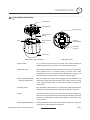
Parts Name & Functions
Lockup Screw
Terminal Cover
Mounting Hole
Drop Prevention
Spring
Fuse
Cabling
Terminal Block
Drop Prevention
Hook
Main Body
Connector
Dome Cover
z Main Body / Terminal Cover
z Dome Cover
z Terminal Cover
Do not detach protection vinyl from dome cover before finishing all
installation process to protect dome cover from scratches or dust.
z Terminal Cover
This is used to install the camera directly on the ceiling or attach to the
other brackets such as in-ceiling, ceiling and wall mount. After
separating this cover first and then attach this directly to ceiling or to
the other bracket. Camera must be assembled at the last stage.
z Drop Prevention Spring
This part keeps the camera from dropping during installation and
Drop Prevention Hook
maintenance. After install the Terminal Cover, please, hang the spring
to the drop prevention hook of main body as shown in picture for
further tasks.
z Lockup Screw
After assembling Terminal Cover to main body, screw Terminal Cover
to main body to protect them from separation by vibration and so on.
z Fuse
If the fuse is burnt to protect your came from over-current damage, the
fuse have to be replace with new one. The fuse specification is 250V 2A.
However, we recommend consulting with supplier to remove the cause
of over-current.
z Cabling Terminal Block
During installation, Power, Video, Communication, Alarm I/O cables are
connected on to this cabling terminal block.
Speed Dome Camera Instruction Manual
8/47
INSTALLATION
2
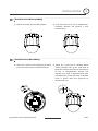
Terminal Cover Disassembling
① Remove the Lockup Screw as shown bellow.
② Turn main body on its axis in CCW(Counterclockwise) direction and separate it from
Terminal Cover.
Terminal Cover Assembling
① Check if the summit of the Plate Spring is located
at the arrow mark as shown in the dotted circle.
② Check the 2 mold line for assembly before
starting assembly. Line up the mold lines as
shown in the dotted circle and turn main body on
its
axis
in
CW(Clockwise)
direction
and
assemble main body to Terminal Cover. After
assembling them, screw main body to Terminal
Cover to protect them from separation by
vibration and so on.
Speed Dome Camera Instruction Manual
9/47
2
INSTALLATION
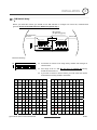
DIP Switch Setup
Before you install the camera, you should set the DIP switches to configure the camera ID, communication
protocol. Do not use the ISP connector. (Authorized person only !)
ISP connector
(for System Upgrade)
Communication
Protocol
Camera ID
ADDRESS (ID)
OPTIONS
Refer to
the Manual
N.C(Normal Close)
N.O(Normal Open)
ON
Terminal
Resistor
ON
1
0
2
0
4
0
8
0
16
0
32
0
64 128
0
0
Camera ID Setup
ID number of camera is set using binary number. The example is
z
ON
ON
shown bellow.
1
2
3
4
5
6
7
The range of ID is 1~255. Do not use 0 as camera ID. Factory
z
8
default of Camera ID is 1.
If you want to control a certain camera, you must match the camera
z
ID with Cam ID setting of DVR or Controller.
Pin
1
2
3
4
5
6
7
8
Pin
1
2
3
4
5
6
7
8
ID
1
2
4
8
16
32
64
128
ID
1
2
4
8
16
32
64
128
1
on
off
off
off
off
off
off
off
11
on
on
off
on
off
off
off
off
2
off
on
off
off
off
off
off
off
12
off
off
on
on
off
off
off
off
3
on
on
off
off
off
off
off
off
13
on
off
on
on
off
off
off
off
4
off
off
on
off
off
off
off
off
14
off
on
on
on
off
off
off
off
5
on
off
on
off
off
off
off
off
15
on
on
on
on
off
off
off
Off
6
off
on
on
off
off
off
off
off
16
off
off
off
off
on
off
off
off
7
on
on
on
off
off
off
off
off
17
on
off
off
off
on
off
off
off
8
off
off
off
on
off
off
off
off
18
off
on
off
off
on
off
off
off
9
on
off
off
on
off
off
off
off
19
on
on
off
Off
on
off
off
off
10
off
on
off
on
off
off
off
off
20
off
off
on
off
on
off
off
off
Speed Dome Camera Instruction Manual
10/47
2
INSTALLATION
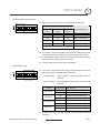
Communication Protocol Setup
z
ON
Select the appropriate Protocol with DIP switch combination.
ON
Switch State
1
2
3
4
5
6
7
8
P0
(Pin 1)
P1
(Pin 2)
P2
(Pin 3)
Protocol/Baud rate
OFF
OFF
OFF
PELCO-D, 2400 bps
ON
OFF
OFF
PELCO-D, 9600 bps
OFF
ON
OFF
PELCO-P, 4800 bps
ON
ON
OFF
PELCO-P, 9600 bps
Otherwise
z
Reserved
If you want to control using DVR or P/T controller, their protocol must
be identical to camera. Otherwise, you can not control the camera.
z
If you changed camera protocol by changing DIP S/W, the change
will be effective after you reboot the camera.
z
Factory default of protocol is “Pelco-D, 2400 bps”.
z
If you want to use Alarm Input, the types of sensor must be selected.
Sensor Type Setup
ON
ON
1
The sensor types are Normal Open and Normal.
2
3
4
5
6
7
~ Normal Open
8
Output Voltage is high state when sensor is
activated.
~ Normal Close
Output Voltage is high state when sensor is not
activated.
Pin No
ST1 (Pin 4)
ST2 (Pin 5)
ST3 (Pin 6)
ST4 (Pin 7)
z
Switch State
Sensor Type
ON
Sensor 1 : Normal Close Type
OFF
Sensor 1 : Normal Open Type
ON
Sensor 2 : Normal Close Type
OFF
Sensor 2 : Normal Open Type
ON
Sensor 3 : Normal Close Type
OFF
Sensor 3 : Normal Open Type
ON
Sensor 4 : Normal Close Type
OFF
Sensor 4 : Normal Open Type
If sensor type is not selected properly, the alarm can be activated
reversely.
Speed Dome Camera Instruction Manual
11/47
2
INSTALLATION
Terminal resistor Setup
ON
Terminal resistor is used if your system is one of following two cases.
ON
1
2
3
4
5
6
7
8
z
Case1: Control cable between camera and controller is
relatively very long (1:1 connection)
If communication cable is very long, the electrical signal will bound
in the terminal point. This reflected signal cause distortion of
original signal. Accordingly, the camera can be out of control. In this
case, the terminal resistor of both sides i.e. camera and controller
must be set to ‘ON’ state.
z
Case2: Multiple cameras are controlled at the same time
Due to similar reasons with case 1, the terminal resisters of
controller and the last camera must be set to ‘ON’ state. Last camera
means decided by cable length. Do not turn on the terminal resistor
of all cameras.
Controller
Terminal Resistor ON
RS-485
#1
#2
Terminal Resistor Terminal Resistor
OFF
OFF
Speed Dome Camera Instruction Manual
#n
Terminal Resistor
ON
12/47
INSTALLATION
2
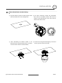
Direct Installation on the Ceiling
① To pass cables to upside of ceiling, please, make
about 50~60mm hole on the ceiling panel.
② For cable connection, remove the pre-defined
hole mark on the Rubber Gasket and locate the
summit of the Plate Spring at the arrow mark as
shown in the dotted circle.
Rubber Gasket
③ After assembling the Rubber Gasket to the
Terminal Cover, install Terminal Cover on ceiling
④ Connect the “Drop Prevention Spring” to the main
body to prevent camera from drop.
tex and connect cables to terminal blocks.
Speed Dome Camera Instruction Manual
13/47
2
INSTALLATION
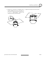
⑤ Check the 2 mold line for assembly before
⑥ Tighten the Lockup Screw as shown bellow.
starting assembly. Line up the mold lines as
shown in the dotted circle and turn main body on
its
axis
in
CW(Clock-Wise)
direction
and
assemble main body to Terminal Cover.
Speed Dome Camera Instruction Manual
14/47
2
INSTALLATION
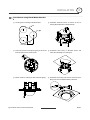
Installation using Flush Mount Bracket
① Cut the panel of ceiling as shown bellow.
② Assemble Terminal Cover of camera to the InCeiling Mount Bracket as shown bellow.
170
3- 80
75
Hole Dimension(mm)
③ Locate the summit of the plate spring at the arrow
mark as shown in the dotted circle.
⑤ Screw camera to ceiling tex with 3 screws tightly.
④ Assemble main body to Terminal Cover and
insert the assembly into ceiling tex.
⑥ Assemble Deco. Ring with camera and turn Deco.
Ring on its axis in CW(Clockwise) direction.
Speed Dome Camera Instruction Manual
15/47
INSTALLATION
2
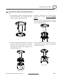
Installation using Pendant Mount Bracket
① To pass cables to upside of ceiling, please make
② Assemble Terminal Cover to Ceiling Mount
about 50~60mm hole on the ceiling panel and
Bracket with 3 screws. (Do not use Rubber
attach the Ceiling mount bracket on it.
Gasket !)
Locate the summit of the Plate Spring at the arrow
mark. (For more information, refer to the “Terminal
Cover Assembling” section)
③ Connect “Drop Prevention Spring” to main body
④ After assembling them, screw main body to
to prevent camera from drop. Line up the mold
Terminal Cover to protect them from separation
lines and turn main body on its axis in
by vibration and so on.
CW(Clockwise) direction and assemble main
body to Terminal Cover.
Speed Dome Camera Instruction Manual
16/47
2
INSTALLATION
Installation using Wall Mount Bracket
① Install Wall Mount Bracket on wall.
② Assemble Terminal Cover to Wall Mount Bracket
with 3 screws. (Do not use Rubber Gasket !)
Locate the summit of the Plate Spring at the arrow
mark. (For more information, refer to the “Terminal
Cover Assembling” section)
③ Connect “Drop Prevention Spring” to main body
④ After assembling them, screw main body to
to prevent camera from drop. Line up the mold
Terminal Cover to protect them from separation
lines and turn main body on its axis in
by vibration and so on.
CW(Clockwise) direction and assemble main
body to Terminal Cover.
Speed Dome Camera Instruction Manual
17/47
INSTALLATION
2
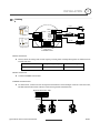
Cabling
Power
IrDA
Sensor
PWR(+)
Door
Switch
IN COM+
IN1
IN2
IN3
IN4
Sensor
RELAY1
Light
PWR(-)
VIDEO(+)
VIDEO(-)
RS-485(+)
RS-485(-)
RELAY2
BNC
Moinitor
RS-485
Alarm
Buzzer
Controller
/ DVR
Output Devices
Terminal Cover
Power Connection
z
Please, check the voltage and current capacity of rated power carefully. Rated power is indicated in the
back of main unit.
Rated Power
Input Voltage Range
Current Consumption
AC 24V
AC 17V ~ 29V
0.6 A
Video Connection
z
Connect with BNC coaxial cable.
RS-485 Communication
z
For PTZ control, connect this line to keyboard and DVR. To control multiple cameras at the same time,
RS-485 communication lines of them is connected in parallel as shown below.
Keyboard Controller / DVR
+ RS-485
Speed Dome Camera Instruction Manual
+ -
+ -
+ -
#1
#2
#n
18/47
2
INSTALLATION
Alarm I/O Connection
z
Sensor Input
Internal
+5V~12V
IN COM+
+
-
IN 1-
Sensor 1 Output
+
-
IN 4-
Sensor 4 Output
+
-
Before connecting sensors, check driving voltage and output signal type of the sensor. Since output
signal types of the sensors are divided into Open Collector and Voltage Output type in general, the
cabling must be done properly after considering these typed. Also, the sensor type, i.e. “Normal Open”
or “Normal Close” in Dip switch in main body of camera must be set properly.
Signal
Description
IN COM+
Connect (+) cable of electric power source for Sensors to this port as
shown in the circuit above.
IN1−, IN2−, IN3−, In4−
z
Connect output of sensors for each port as shown in the circuit above.
Relay Output
Internal
AC or DC
OUT 1
LOAD
AC or DC
OUT 2
LOAD
Maximum allowable electrical load of relay is shown bellow table.
Drive Power
DC Power
AC 110V Power
AC220V Power
Max. Load
DC 28V, 3A
AC110V, 3A
AC250V, 3A
Speed Dome Camera Instruction Manual
19/47
Speed Dome Camera Instruction Manual
20/47
3
OPERATION
Check points before operation
z
Before power is applied, please check the cables carefully.
z
The camera ID of the controller must be identical to that of the target camera. The camera ID can be checked
by reading DIP switch of the camera.
z
If your controller supports multi-protocols, the protocol must be changed to match to that of the camera.
z
If you changed camera protocol by changing DIP switch, the change will be effective after you reboot the
camera.
z
Since the operation method can be different for each controller available, refer to the manual for your
controller if camera can not be controlled properly. The operation of this manual is based on the standard
Pelco® Controller.
Preset and Pattern Function Pre-Check
z
Check how to operate preset and pattern function with controller or DVR in advance to operate camera
function fully when using controller or DVR.
z
z
Refer to the following table when using standard Pelco® protocol controller.
< Go Preset >
Input [Preset Number] and press [Preset] button shortly.
< Set Preset >
Input [Preset Number] and press [Preset] button for more than 2 seconds.
< Run Pattern >
Input [Pattern Number] and press [Pattern] button shortly.
< Set Pattern >
Input [Pattern Number] and press [Pattern] button for more than 2 seconds.
If controller or DVR has no pattern button or function, use shortcut keys with preset numbers. For more
information, refer to “Reserved Preset” in this manual.
Speed Dome Camera Instruction Manual
21/47
3
OPERATION
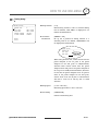
Starting OSD Menu
z Function
Using the OSD menu, Preset, Pattern, Swing, Group and Alarm I/O function can be
configured for each application.
z Enter Menu
<Go Preset> [95]
Reserved Preset
z Description
Some Preset numbers are reserved to special functions.
z Function
<Go Preset> [95]
: Enters into OSD menu
<Go Preset> [131~134] : Runs Pattern Function 1 ~ 4
<Go Preset> [141~148] : Runs Swing Function 1 ~
<Go Preset> [151~158] : Runs Group Function 1 ~ 8
<Go Preset> [161~162] : Sets Relay Output 1 ~ 2 to OFF
<Set Preset> [161~162] : Sets Relay Output 1 ~ 2 to ON
<Go Preset> [167]
: Set Zoom Proportional Function to ON
<Set Preset> [167]
: Set Zoom Proportional Function to OFF
<Go Preset> [170]
: Sets Camera BLC or WDR Mode to OFF
<Go Preset> [171]
: Sets Camera BLC or WDR Mode to ON
<Go Preset> [172]
: Sets Camera Flickerless Mode to OFF
<Go Preset> [173]
: Sets Camera Flickerless Mode to ON
<Go Preset> [174]
: Sets Camera Focus Mode to AUTO
<Go Preset> [175]
: Sets Camera Focus Mode to Manual
<Go Preset> [176]
: Sets Camera Focus Mode to SEMI-AUTO
<Go Preset> [177]
: Sets Day & Night Mode to AUTO
<Go Preset> [178]
: Sets Day & Night Mode to NIGHT
<Go Preset> [179]
: Sets Day & Night Mode to DAY
<Go Preset> [180]
: Sets Line-Lock Mode to OFF
<Go Preset> [181]
: Sets Line-Lock Mode to ON
<Go Preset> [190]
: Sets OSD Display Mode to AUTO (Except Privacy Mask)
<Go Preset> [191]
: Sets OSD Display Mode to OFF (Except Privacy Mask)
<Go Preset> [192]
: Setting OSD Display Mode to ON (Except Privacy Mask)
<Go Preset> [193]
: Sets all Privacy Mask Display to OFF
<Go Preset> [194]
: Sets all Privacy Mask Display to ON
Speed Dome Camera Instruction Manual
22/47
3
OPERATION
Preset
z Function
Max. 127 positions can be stored as Preset position. The Preset number can be assigned
from 1 to 128, but 95 is reserved for starting OSD menu.
Camera characteristics (i.e. White Balance, Auto Exposure) can be set up independently
for each preset. Label should be blank and Relay Outputs should be set to OFF as default.
All characteristics can be set up in OSD menu.
z Set Preset
<Set Preset> [1~128]
z Run Preset
<Go Preset> [1~128]
z Delete Preset
To delete Preset, use OSD menu.
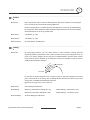
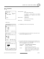
Swing
z Function
By using Swing function, you can make camera to move between 2 Preset positions
repeatedly. When swing function runs, camera moves from the preset assigned as the 1st
point to the preset assigned as the 2nd point in CW(Clockwise) direction. Then camera
moves from the preset assigned as the 2nd point to the preset assigned as the 1st point in
CCW(Counterclockwise) direction.
1
1st Preset
CW
ct
re
Di
2
n
io
W
CC
2nd Preset
ct
re
Di
n
io
In case that the preset assigned as the 1st point is same as the preset assigned as the 2nd
point, camera turns on its axis by 360° in CW(Clockwise) direction and then it turns on its
axis by 360° in CCW(Counterclockwise) direction.
Speed can be set up from 1°/sec to 180°/sec.
z Set Swing
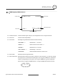
To set Swing, use OSD menu.
z Run Swing
Method 1) <Run Pattern> [Swing NO.+10]
ex) Run Swing 3 : <Run Pattern> [13]
Method 2) <Go Preset> [Swing NO.+140]
ex) Run Swing 3 : <Go Preset> [143]
z Delete Swing
To delete Swing, use OSD menu.
Speed Dome Camera Instruction Manual
23/47
3
OPERATION
Pattern
z Function
Pattern Function is that a camera memorizes the path (mostly curve path) by joystick of
controller for assigned time and revives the path exactly as it memorized.
4 Patterns are available and Maximum 1200 communication commands can be stored in
a pattern.
z Set Pattern
Pattern can be created by one of following two methods.
Method 1) <Set Pattern> [Pattern NO.]
{
Pattern editing screen is displayed as bellow.
EDIT PATTERN 1
[NEAR:SAVE
/FAR:DELETE]
0/0/x1/N
{
Movement by Joystick and preset movement can be memorized in a pattern.
{
The rest memory size is displayed in progress bar.
{
To save the recording, press NEAR key and to cancel, press FAR key.
Method 2) OSD Using OSD Menu: See the section “How to use OSD Menu”.
z Run Pattern
z Delete Pattern
Method 1) <Run Pattern> [Pattern NO.]
ex) Run Pattern 2 : <Run Pattern> [2]
Method 2) <Go Preset> [Pattern NO.+130]
ex) Run Pattern 2: <Go Preset> [132]
Use OSD menu to delete a Pattern.
Speed Dome Camera Instruction Manual
24/47
3
OPERATION
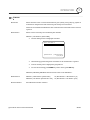
Group
z Function
The group function allows running sequence of Presets, Pattern and/or Swings. Max 8
group can be stored. Each group can have max 20 action entities which can be preset,
pattern or swing. Preset speed can be set up and the repeat number of Pattern & Swing
can be set up in Group setup. Dwell time between actions can be set up also.
Dwell Time
Preset 1
Pattern 1
Swing 1
Max 20 Entities
z Set Group
Use OSD Menu to create a Group.
z Run Group
Method 1) <Run Pattern> [Group NO.+20]
ex) Run Group 7 : <Run Pattern> [27]
Method 2) <Go Preset> [Group NO.++150]
ex) Run Group 7 : <Go Preset> [157]
z Delete Group
Use OSD Menu to delete.
Speed Dome Camera Instruction Manual
25/47
3
OPERATION
Other Functions
z Power Up Action
This function enables to resume the last action executed before power down. Most of
actions such as Preset, Pattern, Swing and Group are available for this function but Jog
actions are not available to resume.
z Auto Flip
In case that tilt angle arrives at the top of tilt orbit(90°), zoom module camera turns on
its axis by 180° at the top of tilt orbit and moves to opposite tilt direction (180°) to keep
tracing targets. If this function is set to OFF, tilt movement range is 0 ~ 95°.
z Parking Action
This function enables to locate the camera to specific position automatically if operator
doesn’t operate the controller for a while. The Park Time can be defined as a interval
from 1 minute to 4 hours.
z Alarm I/O
4 Alarm Input and 2 Alarm output (Relay output) are used. If an external sensor is
activated, camera can be set to move to corresponding preset position. Also, the output
relay can be matched to some specific preset positions to do counteractions such as
turning on the light or sounding the alarm. It is noted that the latest alarm input is
effective if multiple sensors are activated.
z Privacy Zone Mask
To protect privacy, MAX. 8 Privacy Masks can be created on the arbitrary position to
hide objects such as windows, shops or private house. With Spherical Coordinates
system, powerful Privacy Zone Mask function is possible.
z GLOBAL/LOCAL
Image Setup
WB(White Balance) and AE(Auto Exposure) can be set up independently for each
preset. There are 2 modes, "Global" mode & "Local" mode. The Global mode means that
WB or AE can be set up totally and simultaneously for all presets in "ZOOM CAMERA
SETUP" menu. The Local mode means that WB or AE can be set up independently or
separately for each preset in each preset setup menu. Each Local WB/AE value should
activate correspondingly when camera arrives at each preset location.
During jog operation, Global WB/AE value should be applied. All Local WB/AE value
do not change although Global WB/AE value changes.
z SemiAuto Focus
This mode exchanges focus mode automatically between Manual Focus mode and Auto
Focus mode by operation. Manual Focus mode activates in preset operation and Auto
Focus mode activates during jog operation. With Manual mode at presets, Focus data is
memorized in each preset in advance and camera calls focus data in correspondence
with presets as soon as camera arrives at a preset. It should shorten time to get focuses.
Focus mode changes to Auto Focus mode automatically when jog operation starts.
Speed Dome Camera Instruction Manual
26/47
OPERATION
3
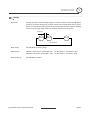
OSD Display of Main Screen
Preset Label
Camera ID
LABEL12345
PRESET1
I:1--- O:-2
15/4/x1/N
CAM 1
Action Title
Alarm Information
P/T/Z Information
z
P/T/Z Information
Current Pan/Tilt angle in degree, zoom magnification and a compass direction.
z
Camera ID
Current Camera ID(Address).
z
Action Title
Followings are possible Action Titles and their meaning.
"SET PRESET ×××"
When Preset ××× is stored
"PRESET ×××"
When camera reach to Preset ×××
"PATTERN ×"
When Pattern × is in action
"SWG×/PRESET ×××"
When Swing × is in action
"UNDEFINED"
When undefined function is called to run
The Label stored for specific Preset.
z
Preset Label
z
Alarm Information This information shows current state of Alarm I/O. The character ‘O’ of first line stands
for Output and ‘I’ of second line means Input. If an I/O point is ON state it will show a
number corresponding to each point. If an I/O point is OFF state, '-' will be displayed.
Ex) Point 2 & 3 of inputs are ON and Point 1 of outputs is ON, OSD will show as below
I:-23- O:1-
Speed Dome Camera Instruction Manual
27/47
HOW TO USE OSD MENU
4
General Rules of Key Operation for Menu
z
The menu items surrounded with (
) always has its sub menu.
z
For all menu level, to go into sub menu, press NEAR key.
z
To go to up-one-level menu, press FAR key.
z
To move from items to item in the menu, use joystick in the Up/Down or Left/Right.
z
To change a value of an item, use Up/Down of the joystick in the controller.
z
Press NEAR key to save values and Press FAR key to cancel values.
z
Specifications and functions should be different by models.
Main Menu
SPEED DOME CAMERA
-----------------------<SYSTEM INFORMATION>
<DISPLAY SETUP>
<DOME CAMERA SETUP>
<SYSTEM INITIALIZE>
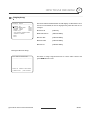
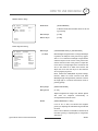
z System Information
Displays system information and configuration.
z Display Setup
Enable/Disable of OSD display on Main
Screen.
z Dome Camera Setup Configure various functions of this camera.
z System Initialize
EXIT
Speed Dome Camera Instruction Manual
Initializes system configuration and sets all
data to factory default configuration.
28/47
HOW TO USE OSD MENU
4
Display Setup
DISPLAY SETUP
-----------------------CAMERA ID
ON
PTZ INFORMATION
AUTO
ACTION TITLE
AUTO
PRESET LABEL
AUTO
ALARM I/O
AUTO
<SET NORTH DIRECTION>
<PRIVACY ZONE>
BACK
EXIT
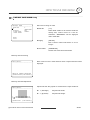
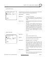
This menu defines Enable/Disable of OSD display on Main Screen. If an
item is set to be AUTO, the item is displayed only when the value of it is
changed.
z Camera ID
[ON/OFF]
z PTZ Information
[ON/OFF/AUTO]
z Action Title
[ON/OFF/AUTO]
z Preset Label
[ON/OFF/AUTO]
z Alarm I/O
[ON/OFF/AUTO]
Compass Direction Setup
SET NORTH DIRECTION
------------------------
Set North to assign compass direction as criteria. Move camera and
press NEAR button to save.
MOVE TO TARGET POSITION
[NEAR:SAVE
/FAR:CANCEL
Speed Dome Camera Instruction Manual
29/47
4
HOW TO USE OSD MENU
PRIVACY ZONE MASK Setup
PRIVACY ZONE
-----------------------MASK NO
1
UNDEFINED
DISPLAY
OFF
CLEAR MASK
CANCEL
<EDIT MASK>
Select area in image to mask.
z Mask No
[1~8]
Select Mask number. If the selected mask has
already data, camera moves as it was set.
Otherwise, “UNDEFINED” will be displayed
under “Mask NO”.
BACK
EXIT
z Display
[ON/OFF]
Sets if camera makes mask shows or not on
images.
z Clear Mask
[CANCEL/OK]
Deletes data in the selected mask NO.
Privacy Zone Area Setup
EDIT MASK 1
------------------------
Move camera to area to mask. Then the menu to adjust mask size will be
displayed.
MOVE TO TARGET POSITION
[NEAR:SELECT/FAR:CANCEL]
Privacy Zone Size Adjustment
EDIT MASK 1
------------------------
[
[
Adjust mask size. Use joystick or arrow buttons to adjust mask size.
z (Left/Right)
Adjusts mask width.
z (Up/Down)
Adjusts mask height.
:ADJUST MASK WIDTH]
:ADJUST MASK HEIGHT]
[NEAR:SAVE
/FAR:CANCEL]
Speed Dome Camera Instruction Manual
30/47
4
HOW TO USE OSD MENU
CAMERA SETUP
ZOOM CAMERA SETUP
-----------------------FOCUS MODE
SEMIAUTO
DIGITAL ZOOM
ON
LINE LOCK
OFF
IMAGE FLIP
OFF
SHARPNESS
16
STABILIZATION
OFF
<WHITE BALANCE SETUP>
<AUTO EXPOSURE SETUP>
BACK
EXIT
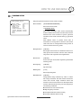
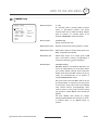
Setup the general functions of zoom camera module.
z Focus Mode
[AUTO/MANUAL/SEMIAUTO]
Sets camera focus mode.
{ SEMIAUTO Mode
This mode exchanges focus mode automatically
between Manual Focus mode and Auto Focus mode.
Manual Focus mode activates in preset operation
and Auto Focus mode activates when jog operation
starts.
With Manual mode at presets, Focus data is
memorized in each preset in advance and camera
calls focus data in correspondence with presets as
soon as camera arrives at a preset.
z Digital Zoom
[ON/OFF]
Sets digital zoom function to ON/OFF. If this is set to
OFF, optical zoom function runs but zoom function
stops at the end of optical zoom magnification.
z Line Lock
[ON/OFF]
If Line lock sync is ON, video signal is synchronized
with AC power.
z Image Flip
[ON/OFF]
Flip the Image.
z Sharpness
[0~32]
Sets image sharpness.
z Stabilization
[ON/OFF]
Compensates image vibration by wind or others.
The image resolution with this function should be
lower than normal image resolution when this
function is turned on because it use the digital zoom
function. Also this function may not work properly in
the following conditions.
Dark scene or Low contrast scene
High frequency vibration
During Pan/Tilt/Zoom/Focus moving
During Iris/Shutter/Gain moving
Speed Dome Camera Instruction Manual
31/47
4
HOW TO USE OSD MENU
White Balance Setup
WB SETUP - GLOBAL
-----------------------WB MODE
AUTO
RED
ADJUST
--BLUE ADJUST
---
BACK
EXIT
z WB Mode
[AUTO/MANUAL]
In Manual mode, Red and Blue level can be set
up manually
z Red Adjust
[0~255]
z Blue Adjust
[0~255]
Auto Exposure Setup
AE SETUP - GLOBAL
-----------------------BACKLIGHT
OFF
DAY/NIGHT
AUTO
BRIGHTNESS
50
IRIS
AUTO
SHUTTER
ESC
AGC
MIDDLE
SSNR
MIDDLE
SENS-UP
<AUTO>
BACK
EXIT
z Backlight
(or WDR)
[OFF/WDR/BLC/HLC] or [OFF/BLC/HLC]
Sets Backlight Compensation. If a bright backlight
is present, the subjects in the picture may appear
dark or as a silhouette. Backlight compensation
enhances objects in the center of the picture. The
camera uses the center of the picture to adjust the
iris. If there is a bright light source outside of this
area, it will wash out to white. The camera will
adjust the iris so that the object in the sensitive
area is properly exposed.
Some modles has WDR(Wide Dynamic Range)
function, which are better function than BLC.
HLC(High Light Compensation) function removes
the high light in a limited environment such as
parking garage.
z Day/Night
[AUTO/DAY/NIGHT]
z Brightness
[0~100]
Adjusts brightness of images. Iris, Shutter Speed
and
Gain
are
adjusted
automatically
in
correspondence with this value.
z IRIS
[AUTO/MANUAL(F1.6~F28)]
If Iris is set to Auto, Iris should have highest
priority in adjusting AE and Shutter Speed should
be fixed.
If Iris is set to Manual, Iris should be fixed and Iris
has lower priority in adjusting AE, in comparison
with others.
Speed Dome Camera Instruction Manual
32/47
4
HOW TO USE OSD MENU
z Shutter Speed
[ESC/A.Flicker/Manual(×256~1/120000 sec)]
If Iris is set to Manual and Shutter Speed is set to
ESC, Shutter Speed should have highest priority. If
Shutter Speed is set to A.Flicker, to remove
Flicker, Shutter Speed should be set to 1/100 sec.
for NTSC and 1/120 for PAL.
z AGC
[OFF/LOW/MIDDLE/HIGH/MANUAL(5~41dB)]
Enhances image brightness automatically in case
that luminance level of image signal is too low.
z SSNR
[OFF/LOW/MIDDLE/HIGH]
Enhances images by deducting noises when gain
level of images is too high.
z SENS-UP
[AUTO(2~256)/OFF]
Activates Slow Shutter function when luminance of
image (signal) is too dark.
It is possible to set up the maximum number of
frames piled up one on another by Slow Shutter
function.
WDR (Wide Dynamic Range) Setup
WDR
-----------------------LIMIT
MIDDLE
LEVEL
50
z Limit
[LOW/MIDDLE/HIGH]
z Level
[0~100]
BACK
EXIT
Speed Dome Camera Instruction Manual
33/47
HOW TO USE OSD MENU
4
HLC (High Light Compensation) Setup
HLC
-----------------------LIMIT
LOW
COLOR
5
z Limit
[AUTO/MANUAL]
When there are too bright lights, this function
blocks light sources on the images to have
better images. For example, when there is a car
coming to a camera at night, this function
bocks car headlights to recognize its number
BACK
EXIT
plate.
z Level
[0~10]
Assigns colors of masks to block light sources
Speed Dome Camera Instruction Manual
34/47
HOW TO USE OSD MENU
4
Motion Setup
Setup the general functions of Pan/Tilt motions.
MOTION SETUP
-----------------------MOTION LOCK
OFF
PWR UP ACTION
ON
AUTO FLIP
ON
JOG MAX SPEED
120/SEC
JOG DIRECTION
INVERSE
FRZ IN PRESET
OFF
<PARKING ACTION SETUP>
<ALARM INPUT SETUP>
BACK
EXIT
z Motion Lock
[ON/OFF]
If Motion Lock is set to ON, it is impossible to
set up and delete Preset, Swing, Pattern and
Group. It is possible only to run those functions.
To set up and delete those functions, enter into
OSD menu.
z Power Up Action
[ON/OFF]
Refer to “Other Functions" section.
z Auto Flip
[ON/OFF]
Refer to “Other Functions" section.
z Jog Max Speed
[1°/sec ~360°/sec]
Sets maximum jog speed. Jog speed is
inversely proportional to zoom magnification.
As zoom magnification goes up, pan/tilt speed
goes down.
z Jog Direction
[INVERSE/NORMAL]
If you set this to ‘Inverse’, the view in the screen
is moving same direction with jog tilting. If
‘Normal’ is selected, the view in the screen is
moving reversely.
z Freeze in Preset
[ON/OFF]
At start point of preset movement, camera
starts freezing the image of start point. Camera
keeps displaying the image of start point
during preset movement and does not display
the images which camera gets during preset
movement. As soon as camera stops at preset
end point, camera starts displaying live images
which it gets at preset end point.
This function availability should be different by
models.
Speed Dome Camera Instruction Manual
35/47
HOW TO USE OSD MENU
4
Parking Action Setup
PARKING ACTION SETUP
-----------------------PARK ENABLE
OFF
WAIT TIME
00:10:00
PARK ACTION
HOME
If Park Enable is set to ON, camera runs assigned function automatically
if there is no PTZ command during assigned "Wait Time".
z Park Enable
[ON/OFF]
z Wait Time
[1~59 sec/1~180 minute]
A camera automatically run a "Part Action" if
BACK
EXIT
there is no command from controller for this time
period.
z Park Action
[HOME/PRESET/PATTERN/SWING/GROUP/PREV
ACTION]
Sets what a camera should do when there is no
command from a controller for the pre-defined
time period (“WAIT TIME”). If Park Action is set to
“HOME”, the camera moves to the home position
which is memorized when the system boots. If
Park Action is set to “PREV. ACTION”, the camera
runs the previous action which it ran most
recently.
Alarm Input Setup
z Alarm No
ALARM INPUT SETUP
-----------------------ALARM NO.
1
ACTION
HOLD TIME
POST ACTION
NOT USED
ENDLESS
HOME
[1~4]
Selects a sensor number to set up.
z Action
[NOT USED/PRESET/PATTERN/SWING/GROUP]
Sets actions to run when sensor is input.
z Hold Time
BACK
EXIT
[ENDLESS/1~59 sec/1~180 minute]
Sets the time period for the action which is run
by external sensor activation. After the time
period passes, the action pre-defined in “Post
Action” runs sequentially in succession to the
action by external sensor activation. If this option
is set to “ENDLESS”, “Post Action” does not
activate.
z Post Action
[HOME/PRESET/PATTERN/SWING/GROUP/PREV
ACTION]
Sets the action that a camera should run after the
time period in“HOLD TIME” passes
Speed Dome Camera Instruction Manual
36/47
4
HOW TO USE OSD MENU
PRESET Setup
PRESET SETUP
-----------------------PRESET NO.
1
CLR PRESET
<EDIT SCENE>
<EDIT LABEL>
<RELAY OUT>
CAM ADJUST
z Preset Number
If a selected preset is already defined, camera
moves
CANCEL
to
pre-defined
position
and
preset
characteristics such as Label and Relay Outputs
LABEL123
1GLOBAL
BACK
EXIT
[1~128]
show on monitor. If a selected preset is not
defined, “UNDEFINED” shows on monitor.
z Clear Preset
[CANCEL/OK]
Delete current Preset data
z Edit Preset Scene
z Edit Preset Label
Redefine current Preset scene position (i.e. PTZ).
Edits Label to show on monitor when preset runs.
MAX. 10 alphabets are allowed.
z Edit Relay Out
Define Relay output. If an Output point is ON
state it will show a number corresponding to
each point. Otherwise, '-' will be displayed.
z CAM Adjust
[GLOBAL/LOCAL]
WB(White Balance) and AE(Auto Exposure) can
be set up independently for each preset. There
are 2 modes, "Global" mode & "Local" mode. The
Global mode means that WB or AE can be set up
totally and simultaneously for all presets in
"ZOOM CAMERA SETUP" menu.
The Local mode means that WB or AE can be set
up independently or separately for each preset
in each preset setup menu. Each Local WB/AE
value should activate correspondingly when
camera arrives at each preset location. During
jog operation, Global WB/AE value should be
applied.
All Local WB/AE value should not change
although Global WB/AE value changes. If “Local’’
is selected, Menu to set WB/AE shows on
monitor.
Speed Dome Camera Instruction Manual
37/47
HOW TO USE OSD MENU
4
Edit Preset Scene
EDIT SCENE - PRESET 1
------------------------
○1 Using Joystick, move camera to desired position.
○2 By pressing NEAR key, save current PTZ data.
○3 Press FAR key to cancel.
MOVE TO TARGET POSITION
[NEAR:SAVE
/FAR:CANCEL]
Edit Preset Label
EDIT LABEL - PRESET 1
-----------------------[
]
---------1234567890
OK
ABCDEFGHIJ
CANCEL
KLMNOPQRST
UVWXYZabcd
efghijklmn
opqrstuvwx
yz<>-/:.
----------
①
Edits label to show on monitor when camera arrives at presets. In
Edit Label menu, a reverse rectangular is cursor. As soon as
finishing selecting alphabet, cursor moves to the next digit.
[
]
Current Cursor Position
②
Using Left/Right/Up/Down of joystick, move to an appropriate
character from the Character set. To choose that character, press
the NEAR key.
---------1234567890
ABCDEFGHIJ
KLMNOPQRST
UVWXYZabcd
efghijklmn
opqrstuvwx
yz<>-/:.
----------
Space Char. Back Space Char.
If you want to use blank, choose Space character (" "). If you want to
delete a character before, use back space character (" ←").
③
If you complete the Label editing, move cursor to "OK" and press
NEAR key to save completed label. To abort current change, move
cursor to "Cancel" and press NEAR key.
Speed Dome Camera Instruction Manual
38/47
HOW TO USE OSD MENU
4
Relay Out Setup
RELAY OUT - PRESET 1
-----------------------RELAY OUT 1
OFF
RELAY OUT 2
OFF
z Relay Out ×
[ON/OFF]
Sets Relay Outputs for assigned preset.
BACK
EXIT
Speed Dome Camera Instruction Manual
39/47
HOW TO USE OSD MENU
4
Swing Setup
SWING SETUP
-----------------------SWING NO.
1
1ST POS.
NOT USED
2ND POS.
NOT USED
SWING SPEED
CLEAR SWING
30/SEC
CANCEL
BACK
EXIT
z Swing Number
[1~8]
Selects Swing number to edit. If a selected Swing
has not defined, "NOT USED" is displayed in 1st
Position and 2nd Position
z 1st Position
2nd Position
[PRESET 1~128]
Set up the 2 position for Swing function. If a
selected preset is not defined, "UNDEFINED" will
be displayed as shown below.
SWING SETUP
-----------------------SWING NO.
1
1ST POS.
PRESET5
2ND POS.
NOT USED
UNDEFINED
When swing function runs, camera moves from the
preset assigned as the 1st point to the preset
assigned as the 2nd point in CW(Clockwise)
direction. Then camera moves from the preset
assigned as the 2nd point to the preset assigned as
the 1st point in CCW(Counterclockwise) direction.
In case that the preset assigned as the 1st point is
same as the preset assigned as the 2nd point,
camera turns on its axis by 360° in CW direction
and then it turns on its axis by 360° in CCW
direction.
z Swing Speed
[1°/sec ~180°/sec]
Sets Swing speed from 1°/sec to 180°/sec.
z Clear Swing
[CANCEL/OK]
Deletes current Swing data.
Speed Dome Camera Instruction Manual
40/47
HOW TO USE OSD MENU
4
Pattern Setup
PATTERN SETUP
-----------------------PATTERN NO.
1
UNDEFINED
CLR PATTERN
CANCEL
<EDIT PATTERN>
z Pattern Number
[1~4 ]
Selects Pattern number to edit.
If a selected
"UNDEFINED"
pattern number is not defined,
will
be
displayed
under
selected pattern number.
z Clear Pattern
BACK
EXIT
[CANCEL/OK]
Deletes data in current pattern
z Edit Pattern
Starts editing pattern.
Edit Pattern
EDIT PATTERN 1
------------------------
①
By using Joystick, move to start position with appropriate zoom. To
start pattern recording, press NEAR key. To exit this menu, press
FAR key.
MOVE TO START POSITION
[NEAR:START /FAR:CANCEL]
②
EDIT PATTERN 1
Move camera with joystick of controller or run preset function to
memorize the path (mostly curve path) in a selected pattern. The
total memory size and the rest memory size is displayed in the
form of bar. Maximum 1200 communication commands can be
stored in a pattern.
[NEAR:SAVE
/FAR:DELETE]
0/0/x1/N
Speed Dome Camera Instruction Manual
③ To save data and exit, press NEAR key. To cancel recording and
delete record data, press FAR key.
41/47
HOW TO USE OSD MENU
4
Group Setup
GROUP SETUP
-----------------------GROUP NO.
1
UNDEFINED
CLEAR GROUP
CANCEL
<EDIT GROUP>
z Group Number
[1~8]
Selects Group number to edit.
If a selected
Group number is not defined,
"UNDEFINED" will be displayed under selected
Group number.
BACK
EXIT
z Clear Group
[CANCEL/OK]
Deletes data in current Group
z Edit Group
Starts editing Group.
Edit Group
EDIT GROUP 1
-----------------------NO ACTION ### DWELL OPT
-----------------------1 NONE
2 NONE
3 NONE
4 NONE
5 NONE
-----------------------BACK
CANCEL
[NEAR:EDIT]
EDIT GROUP 1
-----------------------NO ACTION ### DWELL OPT
-----------------------1 NONE
2 NONE
3 NONE
4 NONE
5 NONE
-----------------------BACK
[NEAR:EDIT ACT]
CANCEL
[FAR :EDIT END]
①
Press Near key in “NO” list to start Group setup.
②
Note that MAX. 20 Functions are allowed in a Group. Move cursor
up/down and press Near key to set up.
③
Set up Action, Dwell time and Option. Note that selected item is
displayed in reverse. Move cursor Left/Right to select items and
EDIT GROUP 1
-----------------------NO ACTION ### DWELL OPT
-----------------------1 NONE
2 NONE
3 NONE
4 NONE
5 NONE
-----------------------BACK
[
:MOVE CURSOR]
CANCEL [
:CHANGE VAL.]
move cursor Up/Down to change each value.
z Action ###
[NONE/PRESET/SWING/PATTERN]
z DWELL
[0 second ~ 4 minutes]
Sets Dwell Time between functions
z OPT
Option. It should be preset speed when
preset is set in Action. It should be the
number of repeat when Pattern or Swing is
selected in Action
Speed Dome Camera Instruction Manual
42/47
4
HOW TO USE OSD MENU
EDIT GROUP 1
-----------------------NO ACTION ### DWELL OPT
-----------------------1 NONE
2 NONE
3 NONE
4 NONE
5 NONE
-----------------------BACK
[
:MOVE CURSOR]
CANCEL [
:CHANGE VAL.]
EDIT GROUP 1
-----------------------NO ACTION ### DWELL OPT
-----------------------1 PRESET
1 00:03 360
2 NONE
3 NONE
4 NONE
5 NONE
-----------------------BACK
[NEAR:EDIT ACT]
CANCEL
[FAR :EDIT END]
EDIT GROUP 1
-----------------------NO ACTION ### DWELL OPT
-----------------------1 PRESET
1 00:03 360
2 NONE
3 NONE
4 NONE
5 NONE
-----------------------BACK
[NEAR:EDIT ACT]
CANCEL
[FAR :EDIT END]
Speed Dome Camera Instruction Manual
④
Set up items such as Action, ###, Dwell and OPT.
⑤
After finishing setting up a Action, press Near key to one-upperlevel menu(Step ②). Move cursor Up/Down to select Action
number and repeat Step ② ~ Step ④ to edit selected Group.
⑥
After finishing setting up all Actions, press FAR key to exit. Then
cursor should be moved to “BACK”. Press Near key to save data.
43/47
HOW TO USE OSD MENU
4
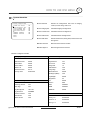
System Initialize
SYSTEM INITIALIZE
-----------------------CLEAR ALL DATA
NO
CLR DISPLAY SET
NO
CLR CAMERA SET
NO
CLR MOTION SET
NO
CLR EDIT DATA
NO
REBOOT CAMERA
NO
REBOOT SYSTEM
NO
BACK
EXIT
z Clear All Data
Deletes all configuration data such as display,
camera, motion setup and so on.
z Clear Display Set
Initializes Display Configuration
z Clear Camera Set
Initializes Camera Configuration
z Clear Motion Set
Initializes Motion Configuration
z Clear Edit Data
Deletes Preset Data, Swing Data, Pattern Data and
Group Data
z Reboot Camera
Reboots Zoom Camera module
z Reboot System
Reboots Speed Dome Camera
Initial Configuration Table
z Display Configuration
z Camera Configuration
Camera ID
ON
Focus Mode
SemiAuto
PTZ Information
AUTO
Digital Zoom
ON
Action Title
AUTO
Line Lock
OFF
Preset Label
AUTO
Sharpness
16
Alarm I/O
AUTO
Stabilization
OFF
North Direction
Pan 0°
Image Flip
OFF
Privacy Zone
Undefined
White Balance
AUTO
Backlight (WDR)
OFF
Day&Night
AUTO
Brightness
50
z Motion Configuration
Iris
AUTO
Motion Lock
OFF
Shutter
ESC
Power Up Action
ON
AGC
MIDDLE
Auto Flip
ON
SSNR
MIDDLE
Jog Max Speed
120°/sec
SENS-UP
AUTO
Jog Direction
INVERSE
Freeze in Preset
OFF
z User Defined Data
Park Action
OFF
Preset 1~128
Undefined
Alarm Action
OFF
Swing 1~8
Undefined
Pattern 1~4
Undefined
Group 1~8
Undefined
Speed Dome Camera Instruction Manual
44/47
5
SPECIFICATIONS
Specifications
Model
Video Signal System
PT127N
PT127P
NTSC
PAL
CCD
1/4'' Super HAD color CCD
Max. Pixels
811(H)×508(V) 410K
795(H)×596(V) 470K
Effective Pixels
768(H)×494(V) 380K
752(H)×582(V) 440K
Horizontal Res.
550 TV Line(Color), 680 TV Line(B/W)
S/N Ratio
50 dB (AGC Off)
×27 Optical Zoom, ×12 Digital Zoom
Zoom
Focal length
f=3.5~94.5mm (F1.6~2.9)
Min. illumination
Camera
0.4 Lux/F1.6 (Color), 0. 02 Lux/F1.6 (B/W), 50 IRE
Day & Night
Auto / Day / Night(ICR)
Focus
Auto / Manual / SemiAuto
Iris
Auto / Manual
Shutter Speed
x256 ~ 1/120000 sec
AGC
Low / Middle / High / Manual / Off
White Balance
BLC / HLC / Off
Flickerless
Selectable
SSNR
Low / Middle / High / Off
Stabilization
On / Off
Range
Pan 360°(Endless) / Tilt 95°
Preset :
Pan/Tilt Speed
Manual :
Swing :
360°/sec
0.05 ~ 360°/sec (proportional to zoom)
1~ 180°/sec
Preset
127 Preset (Label, Camera Image Setting)
Pattern
4 Pattern, 1200 commands(about 5 minute)/Pattern
Swing
8 Swing
Group
8 Group (20 action entities per Group)
Other Functions
Auto Flip, Auto Parking, Power Up Action etc.
Communication
RS-485
Protocol
Pelco-D, Pelco-P selectable
Alarm I/O
4 Input / 2 Output
Privacy Mask Zone
General
z Main Unit
Auto / Manual(Red, Blue Gain Adjustable)
BLC
Pan/Tilt
Appearance
8 Zone
OSD
Menu / PTZ information etc.
Rated Power**
AC 24V / 0.6A
Dome :
Dimension
Housing :
z Pendant Mount
(PMK4)
∅149
∅160 × 212(H) mm
Weight
about 2 Kg
Operating Temp.
0°C ~ 40°C
* Specifications of this product can be subjected to change without notice.
** Check the voltage and current capacity of rated power carefully.
z Flush Mount(FMK4)
Speed Dome Camera Instruction Manual
z Wall Mount(WMK4)
45/47
SPECIFICATIONS
5
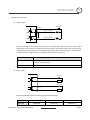
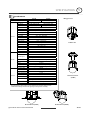
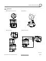
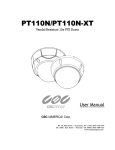
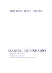
Dimension
z Main Body & Terminal Cover
z Flush Mount
170
115
120
3- 80
Hole Dimension(mm)
120
84.5
104
33
75
149
160
z Pendant Mount
z Wall Mount Bracket
155.6
56.3
56.3
56.3
155.6
84.5
300
84.5
104
31.5
54
104
100.5
31.5
97.5
50
102
97.5
56.3
Unit (mm)
Speed Dome Camera Instruction Manual
46/47
Speed Dome Camera Instruction Manual
47/47


![LS5105 Document No 2 [PDF 1MB] - Australian Electoral Commission](http://vs1.manualzilla.com/store/data/005655823_1-2458abda02bbd8390d0ac9ba8bd86ac6-150x150.png)