1
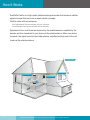
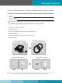
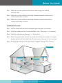
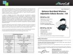
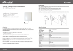
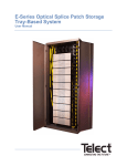
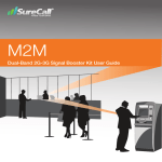
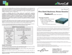
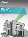
FlexPro
™
2G - 3G Home or Office Signal Booster Kit
User Guide
Thank you for your purchase of SureCall’s FlexPro cellular signal booster kit. FlexPro was
specifically designed to eliminate frustrations over dropped calls, limited range and slow
data rates by amplifying incoming and outgoing cellular signals in homes and offices up
to 6,000 square feet. FlexPro enhances 2G and 3G voice and reception data for all major
U.S. carriers.
If you need any assistance while installing this product please contact tech support at
1-888-365-6283 or email us at: [email protected].
2
SureCall | 48346 Milmont Dirve, Fremont CA 94538 | 1-888-365-6283 | [email protected]
Table of Contents
How It Works
Package Contents
Pg. 4
Pg. 5-6
Installing Your Hardware
Pg. 7
Installation Overview
Pg. 7
Pg. 8
Finding the Strongest Signal
Installing the Outside Anntenna
Pg. 9-10
Installing the Insides Anntenna
Pg. 11-12
Installing Signal Booster
Pg. 13-14
Configure Gain Setting
Pg. 14
Troubleshooting
Pg. 15
Specification
Pg. 17
Warranty
Safety Information
SureCall | 48346 Milmont Dirve, Fremont CA 94538 | 1-888-365-6283 | [email protected]
Pg. 18-19
Pg. 19
3
How It Works
SureCall’s FlexPro is a high-quality bidirectional signal booster that enhances cellular
signals to areas that are prone to weak cellular coverage.
FlexPro works with two antennas:
• An inside antenna that communicates with your cell phone.
• An outside antenna that communicates with the cell tower.
Signals sent from a cell tower are received by the outside antenna, amplified by the
booster and then broadcast to your phone via the inside antenna. When your phone
transmits, the signal is sent to the inside antenna, amplified and then sent to the cell
tower via the outside antenna.
Outside Antenna
Coaxial Cable
Inside Antenna
Signal Booster
4
SureCall | 48346 Milmont Dirve, Fremont CA 94538 | 1-888-365-6283 | [email protected]
Package Contents
1. Unpack all package contents. For missing or damaged items, contact your reseller.
2. Turn over the signal booster and record the model and serial number for reference:
Serial #: Purchase Date: 3. Keep the carton and packing material to store the product in case you need to return it.
Your FlexPro signal booster package includes the following items:
• One SureCall FlexPro signal booster
• One outside antenna
• Cable for connecting the outside antenna to the signal booster
• One inside antenna
• Cable for connecting the inside antenna to the signal booster
• One power supply
FlexPro Signal Booster
Outside Antenna (Option)
Omni
Yagi
SC-400 Cables (2pcs)
Inside Antenna (Option)
Dome
Panel
Warning: Unauthorized antennas, cables, and/or coupling devices are prohibited by FCC new rules. Please contact FCC for details: 1-888-CALL-FCC.
Changes or modifications not expressly approved by SureCall could void the user’s authority to operate the equipment.
SureCall | 48346 Milmont Dirve, Fremont CA 94538 | 1-888-365-6283 | [email protected]
5
Package Contents
Note: FlexPro is available in four kits that are customized to your particular needs.
Please determine which kit you have from the following list:
Model
Package Options
SC-DUALH/O-72-OD-Kit
1 Outdoor Omni antenna, 1 interior dome antenna, 30’ and 75’ SC coax cables
SC-DUALH/O-72-YD-Kit
1 Outdoor Yagi antenna with 1 interior dome antenna, 30’ and 75’ SC coax cables
SC-DUALH/O-72-OP-Kit
1 Outdoor Omni antenna with 1 interior panel antenna, 30’ and 75’ SC coax cables
SC-DUALH/O-72-YP-Kit
1 Outdoor Yagi antenna with 1 interior panel antenna, 30’ and 75’ SC coax cables
For a detailed description, see Kitting Information on page 17
Antenna Type
Model No.
Usage Coverage
Omni Antennas are ideal for
topographies with minimal
obstacles. They offer 360˚
hemispherical coverage
Omni Outdoor Antenna
SC-288W
Yagi Outdoor Antenna
SC-230W-S
Yagi antennas are for targeted
areas and capable of reaching
cell towers up to 30 miles away
Dome Antenna
SC-222W
Dome antennas are for a central
location with 360˚ coverage
Panel Antenna
SC-248W
Panel Antennas allow optimum
reception to targeted areas
Note: Due to the recent change of our company name from Cellphone-Mate (CM) to SureCall (SC) we have changed the prefix on all of our
antennas, cables and accessories from CM to SC-.
6
SureCall | 48346 Milmont Dirve, Fremont CA 94538 | 1-888-365-6283 | [email protected]
Before You Install
Step 1.Make sure you have positioned the booster close enough to an existing
electrical outlet.
Step 2. Make sure you have sufficient cable length between proposed outside antenna
location and booster connector.
Step 3.Make sure you have sufficient cable length between proposed inside antenna
location and booster connector.
Installation Overview
Step 1. Find the outside area that has the strongest signal. (See page 8 for instruction)
Step 2. Install the outside antenna in the area identified in step 1. (See page 9-11 for instruction)
Step 3. Install the inside antenna. (See page 11-12 for instruction)
Step 4. Mount the signal booster, connect the outside and inside antenna cables to the signal
booster, and connect the booster to an AC power source. (See page 13-14 for instruction)
Step 5. Configure gain settings on the signal booster if needed. (See page 14 for instruction)
Outside Antenna
Coaxial Cable
Inside Antenna
Signal Booster
SureCall | 48346 Milmont Dirve, Fremont CA 94538 | 1-888-365-6283 | [email protected]
7
Installing Your Hardware
Step 1. Find
the area with the Strongest Signal
The signal booster requires a minimum cellular signal of low –100 dBm to high –90 dBm.
If your FlexPro Kit includes an outside omni antenna and you can only achieve reception
of one bar or less, you may need a FlexPro yagi antenna which is capable of targeting
carrier antenna towers that are up to 30 miles away. Call or email SureCall for assistance.
Signal readings usually appear as a negative number (for example, -85). The stronger the
signal, the closer it gets to zero. Aim for a signal close to -50 dB. Signals stronger than
-50 dB may cause the booster to shut down (see the graph below). Before installing the
outside antenna, find the area with the strongest cellular signal source from your service
provider by following the directions below. You can also go to www.antennasearch.com
to find the general location of your carrier’s towers.
Measure the strength of the existing cellular signal in various locations
• Apple iPhones: Dial*3001# 12345#* and press Call. In the top-left corner, a number appears instead of bars.
•A
ndroid devices: download apps such as “Network Signal Info” in the Google Play store to measure signal
strength. Search check real signal strength to find other cell signal measurement apps.
• Internet: go to www.speedtest.net
Poor
Good
-60dB
-50dB
-70dB
-80dB
-90dB
-100dB
-110dB
Signal Strength
Excellent
Cell
Tower
Outside
Antenna
2. S
elect a location away from buildings, walls, trees, hills, and other terrain features that can block
or reflect wireless signals (12-inch clear radius is recommended).
Note: Where you install your outside antenna in relation to the carrier’s cell phone tower also determines signal strength. Although cell phone
c
arriers try to place towers for maximum coverage, local ordinances and terrain features can restrict tower locations, which can limit signal
strength at your location.
8
SureCall | 48346 Milmont Dirve, Fremont CA 94538 | 1-888-365-6283 | [email protected]
Installing Your Hardware
Step 2. Install the Outside Antenna
1. Outside Omni antennas receive and send signals in a 360º radius. Yagi, or directional
antennas work best when pointed in the direction of your cell phone carrier’s cell tower.
Mount the outside antenna as high as possible. If you are installing a Yagi antenna set
it up facing the cell tower in the area where you located the best signal source (see step
1 on the previous page).
2. Make sure that the mounting area has least a 12-inch radius clear of obstructions and
other radiating elements.
3. If the mounting area is prone to weak cellular signals or if the density of the roof and
ceiling partially block the signal, the booster will operate at its default setting of 65 dB
gain, be sure to place the outside antenna in a straight line at least 75 feet from the
inside antenna for best performace.
4. Do not colocate antennas or operate the outside antenna with any other antenna or
signal boosters.
5. Run the SC-400 cable from the outside antenna to the signal booster. Do not connect
the cable to the booster at this time.
Note: See next page for outside antenna installation details.
Optional 2 - Outside Yagi
Optional 1- Outside Omni
FlexPro
Note: Due to the recent change of our company name from Cellphone-Mate (CM) to SureCall (SC) we have changed the prefix on all of our
antennas, cables and accessories from CM to SC-.
SureCall | 48346 Milmont Dirve, Fremont CA 94538 | 1-888-365-6283 | [email protected]
9
Installing Your Hardware
FlexPro’s omni antenna comes with equipment for mounting on a vertical wall. For best
results the antenna should be mounted in an upright position.
Step 1: Unscrew antenna from L-mounting bracket on antenna base with hands, or
wrench, if needed.
Step 2: Using vertical plate of bracket, mark position of desired placement with pencil
or marker.
Step 3:Unscrew nut on end of stucco screw and remove it along with lock washer and
regular washer.
Step 4: Place vertical plate into desired location and tap the screws, head first, along
with sleeve, into stucco 1⁄2” to 5/8” deep into place.
Step 5: In this order, place washer, lock washer and nut on each screw and tighten until
secure. When tightening screw, sleeve will expand to secure plate. Screw antenna
securely back onto horizontal plate.
Note: If desired surface for installation plate is wood or concrete, wood or masonry screws for L-plate will have to be purchased separately.
10
SureCall | 48346 Milmont Dirve, Fremont CA 94538 | 1-888-365-6283 | [email protected]
Installing Your Hardware
Step 3. Install the Inside Antenna
Inside antennas come in omni-directional (dome) and flat panel versions.
Table 3 1. Antenna Separation Table
Required Between
Outside and Inside Antenna
tion
ara
sep
a
enn
ant
If the Coverage Area is... Set All Dials to...
and Antenna
Separation is...
3000 - 6000 square feet
65 (default setting) 60 - 80 feet
2000 – 4000 square feet
60
50 – 75 feet
1500 – 2000 square feet
55
40 - 60 feet
1000- 1500 square feet
50
35 – 50 feet
1000 square feet and
below
45 or below
30 - 35 feet
Note: As you can see from the table above, acquiring the recommended inside and outside antenna separation optimizes coverage significantly.
Any reduced antenna separation reduces the booster’s coverage.
1. If your indoor antenna is a dome type, mount it on the ceiling in a central location.
2. If your indoor antenna is a flat panel, install it against a wall or surface projecting the
area where you want reception. Point the antenna away from the outside antenna.
To avoid interference stay a minimum distance of 3 feet from the panel antenna.
Note: see next page for outside antenna installation details.
SureCall | 48346 Milmont Dirve, Fremont CA 94538 | 1-888-365-6283 | [email protected]
11
Installing Your Hardware
The SC-222W multi-band plastic antenna is an omni-directional interior antenna
that gathers signals from all sides. Range of antenna is dependent on three factors:
1) physical obstructions, 2) power generated by booster and 3) reception from
outside signal received and distributed by outside antenna.
Besides the antenna itself, parts include mounting
equipment for either a flat horizontal surface or
a wall. It should be mounted in an upright position
for best results.
Step 1: Drill a 35mm diameter hole in the ceiling. The ceiling thickness should be 20mm,
maximum.
Step 2: Unscrew fixing nut from antenna. Place antenna cable through hole. Screw the
fixing nut back onto antenna and cable on crawl space side of ceiling and fasten.
Step 3: Attach the N-Female connection from the interior antenna to the cable leading
to the connector labeled INSIDE, on your booster.
Step 4: Tighten fixing nut to secure antenna (do not over-tighten).
• Storage and transportation: Store and place in non-extreme room-temperature and
dry environment
• Attention: This antenna should not be used near open fire or flame
12
SureCall | 48346 Milmont Dirve, Fremont CA 94538 | 1-888-365-6283 | [email protected]
Installing Your Hardware
Step 4. Install the Signal Booster
1.Select a location close to a working AC outlet. Do not expose the signal booster to
excessive heat, direct sunlight, moisture, and airtight enclosures. In areas where there
are higher temperatures, install the booster vertically, so air can move between the metal
channels on the faceplate.
2. If you’d like to mount the booster to a wall, mark location of screw tabs on the wall in
the desired location.
3. Use supplied screws or appropriate screws for surface of mounting location and drill
through screw tabs holes on boosters.
4. Connect the outside antenna cable to the signal booster connector marked OUTSIDE
(see page 14). Hand-tighten the connection.
5. Connect the inside antenna cable to the signal booster connector marked INSIDE (see
page 14). Hand-tighten the connection.
6. Connect the AC power cord to the signal booster (see page 14).
7. Connect the plug on the other end of the 110V AC power outlet.
8. Turn the booster’s power switch on.
• The signal booster turns on automatically.
• The Power LED lights up to show that the signal booster is ready for use see
page 14.
• The Alert LED flash up to 15 seconds on each band to show the band is activated
see page 14.
Note: If the Power LED does not turn ON or the Alert LEDs continue to flash, see Troubleshooting page 15.
T
his booster is rated for 5-15V input voltage. DO NOT use the booster with a higher voltage power supply. This can damage the booster, cause
personal injury, and void your warranty.
SureCall | 48346 Milmont Dirve, Fremont CA 94538 | 1-888-365-6283 | [email protected]
13
Installing your Hardware
Booster Hardware
The following image shows the key hardware components on the cellullar booster.
Refer to this image as you install your FlexPro kit components.
FME connector to outside antenna
Alert LED
Alert LED
PCS - 1900 Dial
Cellular - 800 Dial
Programmer
Power Jack
Power Switch
FME connector to inside antenna
Lighting type
Indication
Green light
ON: Power up.
OFF: No power.
Yellow light
ON: Uplink inactivity in that band.
OFF: Working properly.
Yellow light blinking
Blinking: AGC operating.
OFF: Working properly.
Red light blinking
Red light yellow light
alternately blinking
Red light blinking: Shut down
due to oscillation.
OFF: Working properly.
Red light and yellow light
blinking: Self-oscillating.
OFF: Working properly.
Step 5. Configure Gain Settings
1. Find the PCS and Cellular on the top of the signal booster (See above ).
2. Set the dials according to the coverage area and the distance between the indoor and
outdoor antennas (See next page).
14
SureCall | 48346 Milmont Dirve, Fremont CA 94538 | 1-888-365-6283 | [email protected]
Troubleshooting
Table 3 1. Gain Settings Table
If the Coverage Area is... Set All Dials to...
and Antenna
Separation is...
3000 - 6000 square feet
65 (default setting) 60 - 80 feet
2000 – 4000 square feet
60
50 – 75 feet
1500 – 2000 square feet
55
40 - 60 feet
1000- 1500 square feet
50
35 – 50 feet
1000 square feet and
below
45 or below
30 - 35 feet
Note: As you can see from the table above, acquiring the recommended indoor and outdoor antenna separation optimizes coverage
significantly. Any reduced antenna separation reduces the booster’s cellular signal capabilities.
If you Want to Improve Coverage
•F
ind a location that receives a stronger signal and relocate the outside antenna to
that location.
• Increase the distance between the outside and inside antennas.
•B
e sure your signal booster’s dB gain is turned up to maximum gain on each dial (see
page 14).
Warning: Do not adjust the uplink and downlink dB attenuation settings more than 20dB, this could
cause the booster to shut down.
Troubleshooting
In the event you encounter a problem, follow the suggestions below to resolve the issue.
Table 2-1. Troubleshooting Table
Problem
Resolution
Signal booster has no power
Verify that the booster switch is turned on.
Connect the power supply to an alternate power source. Be sure
the AC outlet is working and is not controlled by a wall switch that
can cut power to the outlet. If the green POWER LED on the signal
booster is OFF, return the power supply to SureCall. Contact tech
support at 1-888-365-6283 or [email protected], or go to
www.surecall.com and log on to online support to receive a Return
Merchandise Authorization. (RMA)
After installing your signal
booster system, you have
no signal or reception.
Check the strength of the outside signal as close as you can to the
outside antenna. (see instructions on page 14)
Double-check all signal booster and antenna cable connections.
Be sure your signal booster’s dB gain is turned up to full power on
each dial. (see page 8)
SureCall | 48346 Milmont Dirve, Fremont CA 94538 | 1-888-365-6283 | [email protected]
15
Troubleshooting
Problem
Resolution
LED flashing yellow
This means that the Automatic Gain Control (AGC) is adjusting
which is part of the boosters normal operation
One of the red LEDs next to
the dials on your signal booster
is flashing red.
Turn down the dB gain on the dial until the light goes OFF or turns
yellow. Be sure the inside panel antenna is facing away from the
outside antenna. Use the recommended antenna separation:
65dB: 60 ft. separation
63dB: 50 - 60 ft. separation
55dB: 40 - 50 ft. separation
50dB: 30 - 40 ft. separation
45dB: 20 - 30 ft. separation
40dB: 10 - 20 ft. separation
35dB: 10 ft. separation
Your signal booster restarted
and shut down for 15 minutes,
and is now shut down
permanently.
Each SureCall signal booster is equipped with Auto Shutdown to
prevent cell tower interference. The outside antenna may be close
to a cell tower. Move the outside antenna to a location that provides
sufficient distance from the cell tower to prevent the signal booster
from automatically enabling Auto Shutdown. Once away from the
original location. (see page 8)
The red LED goes ON.
More antenna separation is needed. If you cannot provide more
antenna separation and the Alert LEDs flash after the initial activation
period, lower the dial above the blinking LED by 5dB (for example,
from 50 to 45) and monitor the bars on your cell phone to see
whether reception improves.
The Power LED does not
turn ON.
Be sure the AC outlet is working and is not controlled by a wall
switch that can cut power to the outlet.
The Alert LEDs flash after
the initial activation period.
Lower the dial above the blinking LED by 5dB (for example from 65
to 60) and monitor the are on your cell phone to see whether reception has improved.
The Alert LEDs continue
to flash.
The signal booster shuts down automatically, and then restarts after
60 seconds. Turn down the PCS or Cellular dial that is oscillating to
prevent the signal booster from shutting down automatically.
This may indicate that additional antenna separation is needed.
Your signal booster has
no power.
Verify that the switch on the power supply is turned on and Green
LED is ON.
Connect the power supply to an alternate power source.
Be sure the power source is not controlled by a switch that can
remove power from the outlet.
Check the green POWER LED on the signal booster. If it is OFF,
return the power supply to SureCall. Contact tech support at 1-888365-6283 or [email protected], or go to www.surecall.com and
log on to online support to receive an RMA.
16
SureCall | 48346 Milmont Dirve, Fremont CA 94538 | 1-888-365-6283 | [email protected]
Specification
Specification
FlexPro
Uplink Frequency Range (MHz):
824-849 / 1850-1910
Downlink Frequency Range (MHz):
869-894 / 1930-1990
Supported Standards:
CDMA, WCDMA, GSM, EDGE, HSPA+, EVDO, LTE and all cellular standards
Input/Output Impedance:
50 ohm
Maximum Gain:
65dB-Cellular / 72dB- PCS
Noise Figure:
7dB
VSWR:
≤2.0
AC Input:
5-15V
Maximum Output Power:
1 Watt EIRP
Cable:
SC-400/CM-400
RF Connectors:
N Female (both ends )
Power Consumption:
<10W
Dimensions:
8” x 1.25” x 5”
Weight:
1 lbs 8 oz
FCC (USA):
RSNFLEXPRO
IC (Canada):
7784A-FLEXPRO
Kitting Information
Component
Product Number
Gain / Loss
Cellular 800 MHz
PCS1900 MHz
SC-288W
3 dBi
4 dBi
Outside Antennas*
SC-230W-S
7.5 dBi
8 dBi
SC-230W (option)
10 dBi
11 dBi
Outside Cable
SC-400-75NN (75 Feet)
–4.41dB
–6.17dB
SC-248W
7 dBi
10 dBi
SC-222W
3 dBi
6 dBi
SC-400-30NN (30 Feet)
–1.97 dB
–2.67 dB
Inside Antenna*
Inside Cable
*All equivalent antennas and cables are suitable for use with the FlexPro booster.
Note: Due to the recent change of our company name from Cellphone-Mate (CM) to SureCall (SC) we have changed the prefix on all of
our antennas, cables and accessories from CM to SC-.
SureCall | 48346 Milmont Dirve, Fremont CA 94538 | 1-888-365-6283 | [email protected]
17
Warranty
Three-Year Product Warranty
SureCall warrants its products for three years from the date of purchase against defects in workmanship and/or materials.
Specifications are subject to change. The three-year warranty only applies to products meeting the latest FCC Certification
Guidelines stated on 2/20/2013 and going into effect April 30, 2014. A two-year warranty applies to any products manufactured
before May 1, 2014.
Products returned by customers must be in their original, un-modified condition, shipped in the original or protective packaging
with proof-of-purchase documentation enclosed, and a Return Merchandise Authorization (RMA) number printed clearly on the
outside of the shipping container.
Buyers may obtain an RMA number for warranty returns by calling the SureCall Return Department toll-free at 1-888-3656283. Any returns received by SureCall without an RMA number clearly printed on the outside of the shipping container will
be returned to sender. In order to receive full credit for signal boosters, all accessories originally included in the signal booster
box must be returned with the signal booster. (The Buyer does not need to include accessories sold in addition to the signal
booster, such as antennas or cables.)
This warranty does not apply to any product determined by SureCall to have been subjected to misuse, abuse, neglect, or
mishandling that alters or damages the product’s physical or electronic properties.
SureCall warrants to the Buyer that each of its products, when shipped, will be free from defects in material and workmanship, and will perform in full accordance with applicable specifications. The limit of liability under this warranty is, at SureCall’s
option, to repair or replace any product or part thereof which was purchased up to THREE YEARS after May 1, 2014 or TWO
YEARS for products purchased before May 1, 2014, as determined by examination by SureCall, prove defective in material
and/or workmanship. Warranty returns must first be authorized in writing by SureCall. Disassembly of any SureCall product by
anyone other than an authorized representative of SureCall voids this warranty in its entirety. SureCall reserves the right to make
changes in any of its products without incurring any obligation to make the same changes on previously delivered products.
As a condition to the warranties provided for herein, the Buyer will prepay the shipping charges for all products returned to
SureCall for repair, and SureCall will pay the return shipping with the exception of products returned from outside the United
States, in which case the Buyer will pay the shipping charges.
The Buyer will pay the cost of inspecting and testing any goods returned under the warranty or otherwise, which are found to
meet the applicable specifications or which are not defective or not covered by this warranty.
Products sold by SureCall shall not be considered defective or non-conforming to the Buyer’s order if they satisfactorily fulfill the
performance requirements that were published in the product specification literature, or in accordance with samples provided
by SureCall. This warranty shall not apply to any products or parts thereof which have been subject to accident, negligence,
alteration, abuse, or misuse. SureCall makes no warranty whatsoever in respect to accessories or parts not supplied by it.
18
SureCall | 48346 Milmont Dirve, Fremont CA 94538 | 1-888-365-6283 | [email protected]
Warranty
Limitations of Warranty, Damages and Liability:
EXCEPT AS EXPRESSLY SET FORTH HEREIN, THERE ARE NO WARRANTIES, CONDITIONS, GUARANTEES, OR REPRESENTATIONS AS TO MERCHANTABILITY, FITNESS FOR A PARTICULAR PURPOSE, OR OTHER WARRANTIES, CONDITIONS,
GUARANTEES, OR REPRESENTATIONS, WHETHER EXPRESSED OR IMPLIED, IN LAW OR IN FACT, ORAL OR IN WRITING.
SURECALL AGGREGATE LIABILITY IN DAMAGES OR OTHERWISE SHALL NOT EXCEED THE PAYMENT, IF ANY, RECEIVED
BY CELLPHONE-MATE, INC. FOR THE UNIT OF PRODUCT OR SERVICE FURNISHED OR TO BE FURNISHED, AS THE CASE
MAY BE, WHICH IS THE SUBJECT OF CLAIM OR DISPUTE. IN NO EVENT SHALL SURECALL BE LIABLE FOR INCIDENTAL,
CONSEQUENTIAL, OR SPECIAL DAMAGES, HOWSOEVER CAUSED.
All matters regarding this warranty shall be interpreted in accordance with the laws of the State of California, and any controversy that cannot
be settled directly shall be settled by arbitration in California in accordance with the rules then prevailing of the American Arbitration Association, and judgment upon the award rendered may be entered in any court having jurisdiction thereof. If one or more provisions provided
herein are held to be invalid or unenforceable under applicable law, then such provision shall be ineffective and excluded to the extent of
such invalidity or unenforceability without affecting in any way the remaining provisions hereof.
SAFETY INFORMATION
This is a CONSUMER device.
BEFORE USE, you MUST REGISTER THIS DEVICE with your wireless provider and have your provider’s consent. Most wireless providers
consent to the use of signal boosters. Some providers may not consent to the use of this device on their network. If you are unsure,
contact your provider. You MUST operate this device with approved antennas and cables as specified by the manufacturer. Antennas
MUST be installed at least 20 cm (8 inches) from any person. You MUST cease operating this device immediately if requested by the
FCC or a licensed wireless service provider.
WARNING: E911 location information may not be provided or may be inaccurate for calls served BY USING THIS DEVICE.
48346 Milmont Drive
Fremont, California 94538
USA
888.365.6283
Fax: 510.996.7250
www.surecall.com
SureCall has made a good faith effort to ensure the accuracy of the information in this document and disclaims the implied warranties of
merchantability and fitness for a particular purpose and makes no express warranties, except as may be stated in its written agreement with
and for its customers.SureCall shall not be held liable to anyone for any indirect, special or consequential damages due to omissions or
errors. The information and specifications in this document are subject to change without notice. © 2014. All Rights Reserved. All
trademarks and registered trademarks are the property of their respective owners.
SureCall | 48346 Milmont Dirve, Fremont CA 94538 | 1-888-365-6283 | [email protected]
19
This is a CONSUMER device.
BEFORE USE, you MUST REGISTER THIS DEVICE with your wireless
provider and have your providerÕ
r’ss consent. Most wireless providers consent to
the use of signal boosters. Some providers may not consent to the use of this
device on their network. If you are unsure, contact your provider.
You MUST operate this device with approved antennas and cables as specified
by the manufacturer. Antennas MUST be installed at least 20 cm (8 inches)
from any person.
You MUST cease operating this device immediately if requested by the FCC or
a licensed wireless service provider.
WARNING. E911 location information may not be provided or may be
inaccurate for calls served by using this device.
SureCall | 48346 Milmont Dirve, Fremont CA 94538 | 1-888-365-6283 | [email protected]