1
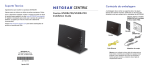
CENTRIA
WNDR4700/WNDR4720
User M anual
350 East Plumeria Drive
San Jose, CA 95134
USA
December 2012
202-11016-02
v1.0
CENTRIA WNDR4700/WNDR4720
Support
Thank you for choosing NETGEAR.
After installing your device, locate the serial number on the label of your product and use it to register your product
at https://my.netgear.com. You must register your product before you can use NETGEAR telephone support.
NETGEAR recommends registering your product through the NETGEAR web site. For product updates and web
support, visit http://support.netgear.com.
Phone (US & Canada only): 1-888-NETGEAR.
Phone (Other Countries): Check the list of phone numbers at
http://support.netgear.com/general/contact/default.aspx.
NETGEAR recommends that you use only the official NETGEAR support resources.
Trademarks
NETGEAR, the NETGEAR logo, and Connect with Innovation are trademarks and/or registered trademarks of
NETGEAR, Inc. and/or its subsidiaries in the United States and/or other countries. Information is subject to change
without notice. © All rights reserved.
2
Contents
Chapter 1
Hardware Setup
Unpack CENTRIA. . . . . . . . . . . . . . . . . . . . . . . . . . . . . . . . . . . . . . . . . . . . . 8
Position CENTRIA . . . . . . . . . . . . . . . . . . . . . . . . . . . . . . . . . . . . . . . . . . . . 8
Hardware Features. . . . . . . . . . . . . . . . . . . . . . . . . . . . . . . . . . . . . . . . . . . . 9
Front and Side Panel . . . . . . . . . . . . . . . . . . . . . . . . . . . . . . . . . . . . . . . . 9
Back Panel . . . . . . . . . . . . . . . . . . . . . . . . . . . . . . . . . . . . . . . . . . . . . . . 11
Label. . . . . . . . . . . . . . . . . . . . . . . . . . . . . . . . . . . . . . . . . . . . . . . . . . . . 11
Install CENTRIA . . . . . . . . . . . . . . . . . . . . . . . . . . . . . . . . . . . . . . . . . . . . . 12
Install an Optional Internal Hard Disk Drive (HDD) . . . . . . . . . . . . . . . . . . 15
HDD Format . . . . . . . . . . . . . . . . . . . . . . . . . . . . . . . . . . . . . . . . . . . . . . 17
Remove a Hard Disk Drive . . . . . . . . . . . . . . . . . . . . . . . . . . . . . . . . . . . . . 17
Requirements for Optional USB Devices . . . . . . . . . . . . . . . . . . . . . . . . . . 19
Chapter 2
Getting Started with NETGEAR genie
Router Setup Preparation. . . . . . . . . . . . . . . . . . . . . . . . . . . . . . . . . . . . . . 21
Use Standard TCP/IP Properties for DHCP . . . . . . . . . . . . . . . . . . . . . . 21
Gather ISP Information. . . . . . . . . . . . . . . . . . . . . . . . . . . . . . . . . . . . . . 21
Wireless Devices and Security Settings . . . . . . . . . . . . . . . . . . . . . . . . . 21
Types of Logins and Access. . . . . . . . . . . . . . . . . . . . . . . . . . . . . . . . . . . . 21
Use NETGEAR genie after Installation. . . . . . . . . . . . . . . . . . . . . . . . . . . . 22
Upgrade the Firmware . . . . . . . . . . . . . . . . . . . . . . . . . . . . . . . . . . . . . . . . 22
Dashboard (Basic Home Screen). . . . . . . . . . . . . . . . . . . . . . . . . . . . . . . . 23
Join Your Wireless Network . . . . . . . . . . . . . . . . . . . . . . . . . . . . . . . . . . . . 24
Manual Method. . . . . . . . . . . . . . . . . . . . . . . . . . . . . . . . . . . . . . . . . . . . 24
Wi-Fi Protected Setup (WPS) Method . . . . . . . . . . . . . . . . . . . . . . . . . . 24
NETGEAR genie App and Mobile genie App . . . . . . . . . . . . . . . . . . . . . . . 25
Chapter 3
NETGEAR genie Basic Settings
Basic Home Screen . . . . . . . . . . . . . . . . . . . . . . . . . . . . . . . . . . . . . . . . . . 27
Internet Setup . . . . . . . . . . . . . . . . . . . . . . . . . . . . . . . . . . . . . . . . . . . . . . . 27
Internet Setup Screen Fields . . . . . . . . . . . . . . . . . . . . . . . . . . . . . . . . . 28
Attached Devices . . . . . . . . . . . . . . . . . . . . . . . . . . . . . . . . . . . . . . . . . . . . 29
Parental Controls . . . . . . . . . . . . . . . . . . . . . . . . . . . . . . . . . . . . . . . . . . . . 30
ReadySHARE Storage . . . . . . . . . . . . . . . . . . . . . . . . . . . . . . . . . . . . . . . . 32
Basic Wireless Settings . . . . . . . . . . . . . . . . . . . . . . . . . . . . . . . . . . . . . . . 33
Wireless Settings Screen Fields. . . . . . . . . . . . . . . . . . . . . . . . . . . . . . . 34
Change WPA Security Option and Password . . . . . . . . . . . . . . . . . . . . 35
Guest Networks . . . . . . . . . . . . . . . . . . . . . . . . . . . . . . . . . . . . . . . . . . . . . 36
Guest Network Wireless Security Options . . . . . . . . . . . . . . . . . . . . . . . 37
3
CENTRIA WNDR4700/WNDR4720
Chapter 4 NETGEAR genie Advanced Home
NETGEAR genie Advanced Home Screen . . . . . . . . . . . . . . . . . . . . . . . . 39
Setup Wizard . . . . . . . . . . . . . . . . . . . . . . . . . . . . . . . . . . . . . . . . . . . . . . . 39
WPS Wizard . . . . . . . . . . . . . . . . . . . . . . . . . . . . . . . . . . . . . . . . . . . . . . . . 40
Setup Menu . . . . . . . . . . . . . . . . . . . . . . . . . . . . . . . . . . . . . . . . . . . . . . . . 41
WAN Setup. . . . . . . . . . . . . . . . . . . . . . . . . . . . . . . . . . . . . . . . . . . . . . . . . 42
Default DMZ Server . . . . . . . . . . . . . . . . . . . . . . . . . . . . . . . . . . . . . . . . 43
Change the MTU Size . . . . . . . . . . . . . . . . . . . . . . . . . . . . . . . . . . . . . . 44
LAN Setup . . . . . . . . . . . . . . . . . . . . . . . . . . . . . . . . . . . . . . . . . . . . . . . . . 45
LAN Setup Screen Settings . . . . . . . . . . . . . . . . . . . . . . . . . . . . . . . . . . 46
Use the Router as a DHCP Server. . . . . . . . . . . . . . . . . . . . . . . . . . . . . 47
Address Reservation . . . . . . . . . . . . . . . . . . . . . . . . . . . . . . . . . . . . . . . 48
Quality of Service (QoS) Setup . . . . . . . . . . . . . . . . . . . . . . . . . . . . . . . . . 48
Chapter 5 Storage
ReadySHARE Access . . . . . . . . . . . . . . . . . . . . . . . . . . . . . . . . . . . . . . . . 53
User Setup . . . . . . . . . . . . . . . . . . . . . . . . . . . . . . . . . . . . . . . . . . . . . . . . . 53
File-Sharing Scenarios . . . . . . . . . . . . . . . . . . . . . . . . . . . . . . . . . . . . . . . . 54
Storage Basic Settings . . . . . . . . . . . . . . . . . . . . . . . . . . . . . . . . . . . . . . . . 56
Add or Edit a Network Folder . . . . . . . . . . . . . . . . . . . . . . . . . . . . . . . . . 57
Storage Advanced Settings . . . . . . . . . . . . . . . . . . . . . . . . . . . . . . . . . . . . 58
Safely Remove a USB or Internal Hard Drive . . . . . . . . . . . . . . . . . . . . . . 59
Media Server . . . . . . . . . . . . . . . . . . . . . . . . . . . . . . . . . . . . . . . . . . . . . . . 60
Specify Approved USB Devices . . . . . . . . . . . . . . . . . . . . . . . . . . . . . . . . . 60
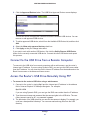
Connect to the USB Drive from a Remote Computer. . . . . . . . . . . . . . . . . 61
Access the Router’s USB Drive Remotely Using FTP . . . . . . . . . . . . . . . . 61
ReadySHARE Cloud . . . . . . . . . . . . . . . . . . . . . . . . . . . . . . . . . . . . . . . . . 62
Back Up Your Computers. . . . . . . . . . . . . . . . . . . . . . . . . . . . . . . . . . . . . . 63
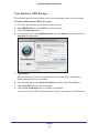
ReadySHARE Vault Windows Backup . . . . . . . . . . . . . . . . . . . . . . . . . . 63
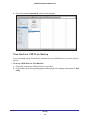
Time Machine HDD Backup . . . . . . . . . . . . . . . . . . . . . . . . . . . . . . . . . . 65
Time Machine USB Drive Backup . . . . . . . . . . . . . . . . . . . . . . . . . . . . . 66
Back Up an SD Card onto the Internal HDD . . . . . . . . . . . . . . . . . . . . . 70
Replace the Internal Hard Disk Drive . . . . . . . . . . . . . . . . . . . . . . . . . . . . . 71
Format the HDD . . . . . . . . . . . . . . . . . . . . . . . . . . . . . . . . . . . . . . . . . . . . . 73
Chapter 6 ReadySHARE Printer
ReadySHARE Printer . . . . . . . . . . . . . . . . . . . . . . . . . . . . . . . . . . . . . . . . . 76
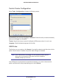
USB Control Center Utility . . . . . . . . . . . . . . . . . . . . . . . . . . . . . . . . . . . . . 80
Control Center Configuration . . . . . . . . . . . . . . . . . . . . . . . . . . . . . . . . . 81
USB Printer. . . . . . . . . . . . . . . . . . . . . . . . . . . . . . . . . . . . . . . . . . . . . . . 81
Scan with a Multifunction Printer . . . . . . . . . . . . . . . . . . . . . . . . . . . . . . 82
Chapter 7 Security
Keyword Blocking of HTTP Traffic . . . . . . . . . . . . . . . . . . . . . . . . . . . . . . . 84
Block Services (Port Filtering) . . . . . . . . . . . . . . . . . . . . . . . . . . . . . . . . . . 85
4
CENTRIA WNDR4700/WNDR4720
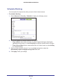
Schedule Blocking . . . . . . . . . . . . . . . . . . . . . . . . . . . . . . . . . . . . . . . . . . . 87
Security Event Email Notifications . . . . . . . . . . . . . . . . . . . . . . . . . . . . . . .88
Chapter 8
Administration
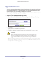
Upgrade the Firmware . . . . . . . . . . . . . . . . . . . . . . . . . . . . . . . . . . . . . . . .90
View Router Status. . . . . . . . . . . . . . . . . . . . . . . . . . . . . . . . . . . . . . . . . . . 91
Router Information . . . . . . . . . . . . . . . . . . . . . . . . . . . . . . . . . . . . . . . . .91
Internet Port (WAN) Setup . . . . . . . . . . . . . . . . . . . . . . . . . . . . . . . . . . .92
Wireless Settings (2.4 GHz and 5 GHz) . . . . . . . . . . . . . . . . . . . . . . . . .94
View Logs of Web Access or Attempted Web Access . . . . . . . . . . . . . . . .95
Manage the Configuration File . . . . . . . . . . . . . . . . . . . . . . . . . . . . . . . . . .96
Back Up Settings . . . . . . . . . . . . . . . . . . . . . . . . . . . . . . . . . . . . . . . . . . 96
Restore Configuration Settings. . . . . . . . . . . . . . . . . . . . . . . . . . . . . . . .96
Erase . . . . . . . . . . . . . . . . . . . . . . . . . . . . . . . . . . . . . . . . . . . . . . . . . . . 97
Set Password . . . . . . . . . . . . . . . . . . . . . . . . . . . . . . . . . . . . . . . . . . . . . . . 97
Password Recovery . . . . . . . . . . . . . . . . . . . . . . . . . . . . . . . . . . . . . . . .97
Chapter 9
Advanced Settings
Advanced Wireless Settings. . . . . . . . . . . . . . . . . . . . . . . . . . . . . . . . . . .100
Restrict Wireless Access by MAC Address . . . . . . . . . . . . . . . . . . . . .101
Wireless AP . . . . . . . . . . . . . . . . . . . . . . . . . . . . . . . . . . . . . . . . . . . . . . . 102
Wireless Repeating Function (WDS) . . . . . . . . . . . . . . . . . . . . . . . . . . . .103
Set Up the Base Station . . . . . . . . . . . . . . . . . . . . . . . . . . . . . . . . . . . .105
Set Up a Repeater Unit. . . . . . . . . . . . . . . . . . . . . . . . . . . . . . . . . . . . .106
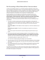
Port Forwarding and Triggering . . . . . . . . . . . . . . . . . . . . . . . . . . . . . . . .107
Remote Computer Access Basics . . . . . . . . . . . . . . . . . . . . . . . . . . . .107
Port Triggering to Open Incoming Ports . . . . . . . . . . . . . . . . . . . . . . . .108
Port Forwarding to Permit External Host Communications . . . . . . . . .110
How Port Forwarding Differs from Port Triggering . . . . . . . . . . . . . . . .111
Set Up Port Forwarding to Local Servers . . . . . . . . . . . . . . . . . . . . . . . . .111
Add a Custom Service . . . . . . . . . . . . . . . . . . . . . . . . . . . . . . . . . . . . .112
Edit or Delete a Port Forwarding Entry . . . . . . . . . . . . . . . . . . . . . . . . .113
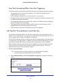
Set Up Port Triggering . . . . . . . . . . . . . . . . . . . . . . . . . . . . . . . . . . . . . . .113
Dynamic DNS . . . . . . . . . . . . . . . . . . . . . . . . . . . . . . . . . . . . . . . . . . . . . . 115
Static Routes . . . . . . . . . . . . . . . . . . . . . . . . . . . . . . . . . . . . . . . . . . . . . . 116
Remote Management . . . . . . . . . . . . . . . . . . . . . . . . . . . . . . . . . . . . . . . .118
USB Settings . . . . . . . . . . . . . . . . . . . . . . . . . . . . . . . . . . . . . . . . . . . . . . 119
Universal Plug and Play . . . . . . . . . . . . . . . . . . . . . . . . . . . . . . . . . . . . . .119
IPv6 . . . . . . . . . . . . . . . . . . . . . . . . . . . . . . . . . . . . . . . . . . . . . . . . . . . . . 120
Auto Detect Fields . . . . . . . . . . . . . . . . . . . . . . . . . . . . . . . . . . . . . . . .121
Auto Config . . . . . . . . . . . . . . . . . . . . . . . . . . . . . . . . . . . . . . . . . . . . . . 122
6to4 Tunnel. . . . . . . . . . . . . . . . . . . . . . . . . . . . . . . . . . . . . . . . . . . . . . 123
Pass Through . . . . . . . . . . . . . . . . . . . . . . . . . . . . . . . . . . . . . . . . . . . . 123
Fixed . . . . . . . . . . . . . . . . . . . . . . . . . . . . . . . . . . . . . . . . . . . . . . . . . . . 124
DHCP . . . . . . . . . . . . . . . . . . . . . . . . . . . . . . . . . . . . . . . . . . . . . . . . . . 125
PPPoE . . . . . . . . . . . . . . . . . . . . . . . . . . . . . . . . . . . . . . . . . . . . . . . . . 126
Traffic Meter . . . . . . . . . . . . . . . . . . . . . . . . . . . . . . . . . . . . . . . . . . . . . . . 126
5
CENTRIA WNDR4700/WNDR4720
Chapter 10
Troubleshooting
Quick Tips . . . . . . . . . . . . . . . . . . . . . . . . . . . . . . . . . . . . . . . . . . . . . . . . 129
Sequence to Restart Your Network . . . . . . . . . . . . . . . . . . . . . . . . . . . 129
Check Ethernet Cable Connections . . . . . . . . . . . . . . . . . . . . . . . . . . . 129
Hard Disk Drive (HDD) . . . . . . . . . . . . . . . . . . . . . . . . . . . . . . . . . . . . . 129
Wireless Settings . . . . . . . . . . . . . . . . . . . . . . . . . . . . . . . . . . . . . . . . . 129
Network Settings . . . . . . . . . . . . . . . . . . . . . . . . . . . . . . . . . . . . . . . . . 130
Troubleshooting with the LEDs . . . . . . . . . . . . . . . . . . . . . . . . . . . . . . . . 130
Power LED Is Off or Blinking . . . . . . . . . . . . . . . . . . . . . . . . . . . . . . . . 130
Power LED Stays Amber . . . . . . . . . . . . . . . . . . . . . . . . . . . . . . . . . . . 130
HDD LED Is Red or Red and Green. . . . . . . . . . . . . . . . . . . . . . . . . . . 131
LEDs Never Turn Off . . . . . . . . . . . . . . . . . . . . . . . . . . . . . . . . . . . . . . 131
Internet LED Is Off . . . . . . . . . . . . . . . . . . . . . . . . . . . . . . . . . . . . . . . . 131
Wireless LED Is Off . . . . . . . . . . . . . . . . . . . . . . . . . . . . . . . . . . . . . . . 131
Cannot Log In to CENTRIA . . . . . . . . . . . . . . . . . . . . . . . . . . . . . . . . . . . 132
Cannot Access the Internet . . . . . . . . . . . . . . . . . . . . . . . . . . . . . . . . . . . 132
Troubleshoot PPPoE . . . . . . . . . . . . . . . . . . . . . . . . . . . . . . . . . . . . . . 134
Troubleshooting Internet Browsing. . . . . . . . . . . . . . . . . . . . . . . . . . . . 134
Changes Not Saved . . . . . . . . . . . . . . . . . . . . . . . . . . . . . . . . . . . . . . . . . 135
Wireless Connectivity . . . . . . . . . . . . . . . . . . . . . . . . . . . . . . . . . . . . . . . . 135
Wireless Signal Strength . . . . . . . . . . . . . . . . . . . . . . . . . . . . . . . . . . . 135
Restore the Factory Settings and Password . . . . . . . . . . . . . . . . . . . . . . 136
Troubleshoot Your Network Using the Ping Utility . . . . . . . . . . . . . . . . . . 136
Test the LAN Path to CENTRIA . . . . . . . . . . . . . . . . . . . . . . . . . . . . . . 136
Test the Path from Your Computer to a Remote Device . . . . . . . . . . . 137
Appendix A Supplemental Information
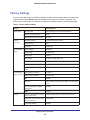
Factory Settings . . . . . . . . . . . . . . . . . . . . . . . . . . . . . . . . . . . . . . . . . . . . 139
Technical Specifications. . . . . . . . . . . . . . . . . . . . . . . . . . . . . . . . . . . . . . 140
Appendix B Notification of Compliance
6
1.
Hardware Setup
Get ti ng to know your CEN T RI A
1
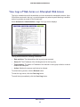
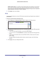
NETGEAR CENTRIA is an all-in-one device with three essential functions.
•
Back up automatically. All your computers—Windows PCs and Macs—can back up
incrementally on the CENTRIA internal hard drive or on an external USB storage drive.
•
Share easily. Store your files and media on your CENTRIA and access or stream them
from any Internet-enabled device.
•
Connect quickly. Enjoy high-performance connectivity throughout your home with your
900 Mbps, dual-band WiFi router.
CENTRIA comes in two models: WNDR4720, which comes with a 2 TB hard drive, and
WNDR4700, for which you provide your own hard drive. You can upgrade the hard disk drive at
any time. Both models have two SuperSpeed USB 3.0 ports for adding even more storage,
should you need it. An SD card reader affords simple, single-click backup of media to the internal
hard drive.
This chapter contains the following sections:
•
Unpack CENTRIA
•
Position CENTRIA
•
Hardware Features
•
Install an Optional Internal Hard Disk Drive (HDD)
•
Remove a Hard Disk Drive
•
Requirements for Optional USB Devices
For information about ReadySHARE features in your product, see Chapter 5, Storage, and visit
www.netgear.com/readyshare.
For more information about the topics covered in this manual, visit the support website at
http://support.netgear.com.
7
CENTRIA WNDR4700/WNDR4720
Unpack CENTRIA
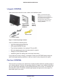
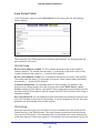
Open the box and remove the router, cables, and installation guide.
Note: If you purchased model
WNDR4720, your hard disk drive
was shipped external to CENTRIA to
protect it from any accidental
damage. Always remove the hard
drive from the internal slot when
shipping CENTRIA.
CENTRIA
Tray for
0.75-inch
HDD only
Hard disk drive
(HDD) included
only with model
WNDR4720
Ethernet cable
Power adapter
Figure 1. Check the package contents
Your box contains the following items:
•
CENTRIA WNDR4700/WNDR4720
•
HDD (model WNDR4720 only)
•
Tray to allow installation of an optional 0.75-inch HDD
•
AC power adapter and power cord (plug varies by region)
•
Category 5 (Cat 5) Ethernet cable
•
Installation guide with cabling and router setup instructions
If any parts are incorrect, missing, or damaged, contact your NETGEAR dealer. Keep the
carton and original packing materials, in case you need to return the product for repair.
Position CENTRIA
The router lets you access your network from virtually anywhere within the operating range of
your wireless network. However, the operating distance or range of your wireless connection
can vary significantly depending on the physical placement of your router. For example, the
thickness and number of walls the wireless signal passes through can limit the range. For
best results, place your router:
Hardware Setup
8
CENTRIA WNDR4700/WNDR4720
•
Near the center of the area where your computers and other devices operate and
preferably within line of sight to your wireless devices.
•
So it is accessible to an AC power outlet and near Ethernet cables for wired computers.
•
In an elevated location such as a high shelf, keeping the number of walls and ceilings
between the router and your other devices to a minimum.
•
Away from electrical devices that are potential sources of interference. Equipment that
might cause interference includes ceiling fans, home security systems, microwaves,
computers, the base of a cordless phone, or 2.4 GHz cordless phone.
•
Away from any large metal surfaces, such as a solid metal door or aluminum studs. Large
expanses of other materials such as glass, insulated walls, fish tanks, mirrors, brick, and
concrete can also affect your wireless signal.
When there is more than one wireless network in the area and they use the same channel,
that can create interference in some instances. If this happens, you can use a different radio
frequency channel to reduce interference. The recommended channel spacing is five
channels. Fr example, different networks in the same area could use Channels 1 and 6, or 6
and 11.
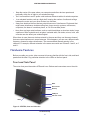
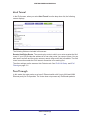
Hardware Features
Before you cable your router, take a moment to become familiar with the front, side, and back
panels and the label. Pay particular attention to the LEDs on the front panel.
Front and Side Panel
The router front panel has status LEDs and icons. Buttons and connectors are on the side.
WPS
WiFi On/Off
Backup
USB port
SD card reader
LEDs
Figure 2. CENTRIA, front and side view
Hardware Setup
9
CENTRIA WNDR4700/WNDR4720
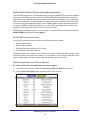
Table 1. LED description
LED
Description
Power
•
•
•
•
•
Internet
• Solid green. The Internet connection is ready.
• Solid amber. The Ethernet cable connection to the modem has been detected.
• Off. No Ethernet cable is connected to CENTRIA.
Wireless
• Solid blue. The wireless radio is operating in either 2.4 GHz or 5 GHz mode.
• Blinking. The router is in WPS (WiFi protected setup) mode.
• Off. The wireless radios are off for both 2.4 GHz and 5 GHz.
USB
• Solid blue: The router has accepted the USB device. The USB device is ready to
be used.
• Blinking blue. A USB device is plugged in and is trying to connect.
• Off. No USB device is connected; someone clicked the Safely Remove Hardware
button, and it is now safe to remove the attached USB device.
HDD
• Solid green. The internal HDD is working and is not full.
• Solid green plus red. The HDD is 85% full.
• Blinking green. Someone pressed the Backup button; the SD card data is being
copied to the internal HDD.
• Blinking green and red. The HDD is 95% full.
• Solid red. The HDD is not formatted, the HDD connection is loose, or there is a
failure alert.
• Off. No internal HDD is connected.
Solid amber. CENTRIA is starting up.
Blinking amber. The firmware is upgrading, or the Reset button was pressed.
Solid green. CENTRIA is ready.
Blinking green. The firmware is corrupted. Visit www.netgear.com/support.
Off. Power is not supplied to CENTRIA.
The following are located on the side.
•
WiFi On/Off button. Pressing and holding the WiFi On/Off button for 2 seconds turns on
or off the 2.4 GHz and 5 GHz wireless radios. If the Wireless LED is lit, then the wireless
radio is on. If the LED is off, then the wireless radios are turned off and you cannot
connect wirelessly to the router.
•
WPS button. You can use this button to use WPS to add a wireless device or computer
to your wireless network.
•
Backup button. You can use this button to back up files and folders onto the internal
hard disk drive from an SD card attached to the card reader. See Back Up an SD Card
onto the Internal HDD on page 70.
•
USB drive. You can use this to attach a USB device such as a flash drive. Files and
folders on the USB device can be shared.
•
SD card reader. The SD card reader supports SD, MMC, MS, or MS Pro type cards. You
can attach an SD card here, and then use the Backup button to back up files and folders
on the SD card onto the internal HDD.
Hardware Setup
10
CENTRIA WNDR4700/WNDR4720
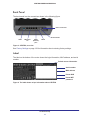
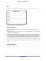
Back Panel
The back panel has the connections shown in the following figure.
Power connector
Power On/Off
USB
LAN ports
1-4
WAN
(Internet)
port
Reset
Figure 3. CENTRIA, rear view
See Factory Settings on page 139 for information about restoring factory settings.
Label
The label on the bottom of the router shows the login information, MAC address, and serial
number.
Default access information
Serial number
MAC address
Preset SSID
Preset WiFi
password
Figure 4. The label shows unique information about CENTRIA
Hardware Setup
11
CENTRIA WNDR4700/WNDR4720
Install CENTRIA
To view the CENTRIA Installation video, visit
http://kb.netgear.com/app/answers/detail/a_id/21753/~/centria-hard-drive-installation-video,
or use the following QR code.
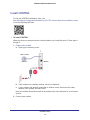
To install CENTRIA:
Make sure that your Internet service is working before you install the router. Follow steps 1
through 5.
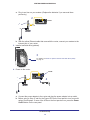
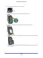
1. Prepare your modem.
a. Unplug your modem’s power.
1
DSL or cable
Internet
Modem
b. If the modem has a battery backup, remove its batteries.
c. If your modem was already connected to another router, disconnect the cable
between your modem and that router.
Now your modem should be turned off and cabled only to the wall jack for your Internet
service.
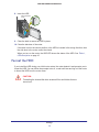
2. Connect your modem.
Hardware Setup
12
CENTRIA WNDR4700/WNDR4720
a. Plug in and turn on your modem. (Replace the batteries if you removed them
previously.)
2
Router
b
a
Modem
b. With the yellow Ethernet cable that came with the router, connect your modem to the
Internet port of your router.
3. Install a hard disk drive (optional).
3
For details, see Install an Optional Internal Hard Disk Drive (HDD)
on page 15.
4. Power on the router.
On/Off
4
Router
Modem
a. Connect the power adapter to the router and plug the power adapter into an outlet.
b. Before going to Step 5, wait for the Power LED on the front panel to turn from solid
amber to solid green. If none of the LEDs on the front panel are on, press the Power
On/Off button on the rear panel.
Hardware Setup
13
CENTRIA WNDR4700/WNDR4720
5. Connect a computer.
Router
Modem
5
You can use an Ethernet cable (not included) or connect wirelessly.
•
Use an Ethernet cable to connect your computer to an Ethernet port on your Router.
•
Or, connect wirelessly by using the preset SSID and preset WiFi password on the
label on the bottom of the router.
6. Launch a browser, and the genie screen displays.
7. Click Next, and follow the onscreen instructions to set up your router.
• If you installed an HDD, you can format it when prompted, or do that later.
•
During installation, you can download and install the ReadySHARE Vault app, or do
that later. ReadySHARE Vault lets you manage your backups from your computer.
See ReadySHARE Vault Windows Backup on page 63.
If the browser cannot display the web page:
•
Make sure that the computer is connected to one of the four LAN Ethernet ports or
wirelessly to the router.
•
Make sure that the router Power LED
•
Close and reopen the browser to make sure that the browser does not cache the previous
page.
•
Browse to http://www.routerlogin.net.
is green and that its Wireless LED
Hardware Setup
14
is lit.
CENTRIA WNDR4700/WNDR4720
•
If the computer is set to a static or fixed IP address (this is uncommon), change it to
obtain an IP address automatically from the router. Consult the documentation that came
with your computer or operating system for instructions about how to do this.
If the router does not connect to the Internet:
1. Review your settings to be sure that you have selected the correct options and typed
everything correctly.
2. Contact your ISP to verify that you have the correct configuration information.
3. Read Chapter 11, Troubleshooting. If problems persist, register your NETGEAR product and
contact NETGEAR technical support.
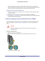
Install an Optional Internal Hard Disk Drive (HDD)
CENTRIA supports an optional HDD. The router supports 3.5-inch SATA HDDs (both 0.75
and 1-inch thickness). Visit www.netgear.com/CENTRIA_HD for list of compatible hard
drives.
CAUTION:
To protect your equipment, always turn off the router before removing or
inserting an HDD.
To install a hard disk drive:
1. Make sure the router is powered off.
2. Open the router side door (a) and move the internal latch down (b) as shown (c).
a
b
c
This allows you to insert the HDD.
Hardware Setup
15
CENTRIA WNDR4700/WNDR4720
3. If you are installing a 0.75-inch-thick HDD (this is uncommon), insert the tray into the router.
Follow the THIS SIDE UP and the BACK OF PRODUCT signs on the tray to place it in the
correct orientation.
4. Insert the HDD.
The metal connector on the HDD is up.
5. Close the latch to secure the HDD in place.
6. Close the side door.
Note: If the latch is not in the correct position or the HDD is inserted in the
wrong direction, then the side door to the router cannot be closed.
When you turn on the router, the HDD LED shows the status of the HDD.
•
Solid green. The internal HDD is working and is not full.
•
Solid green plus red. The HDD is 85% full.
•
Solid red. The HDD is not formatted, the HDD connection is loose, or there is a failure
alert.
•
Off. No internal HDD is connected.
Hardware Setup
16
CENTRIA WNDR4700/WNDR4720
HDD Format
If you install an HDD during your initial router setup, the router detects it. A preformatted HDD
does not have to be reformatted. If the HDD has not yet been formatted, you are prompted to
format the HDD.
CAUTION:
Formatting the hard disks erases any data stored on it.
You can follow the prompts to do so, or wait until later and log in to the router to format the
HDD from the router menu. See Format the HDD on page 73.
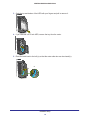
Remove a Hard Disk Drive
CAUTION:
To protect your equipment, always turn off the router before removing or
inserting a hard disk drive (HDD).
To remove the hard disk drive (HDD):
1. Power off the router with the Power On/Off button.
2. Open the router side door and release the internal latch as shown.
Hardware Setup
17
CENTRIA WNDR4700/WNDR4720
3. Grab the top and bottom of the HDD with your fingers and pull to remove it.
4. If you removed a 0.75-inch HDD, remove the tray from the router.
5. Place the latch back to the left (a) so that the router side door can be closed (b).
a
b
Hardware Setup
18
CENTRIA WNDR4700/WNDR4720
Requirements for Optional USB Devices
The router works with USB 3.0 (USB Super Speed), 2.0 (USB High Speed), and 1.0 and 1.1
(USB Full Speed) standards. The approximate USB bus speeds are shown in the following
table. Actual bus speeds can vary, depending on the CPU speed, memory, speed of the
network, and other variables.
Table 2. USB drive speeds
Bus
Speed/Sec
USB 3.0
5,000 Mbits
USB 2.0
480 Mbits
USB 1.1
12 Mbits
The router works with most USB-compliant external flash and hard drives. For the most
up-to-date list of USB drives that the router supports, go to:
http://kbserver.netgear.com/readyshare
The router supports both read and write for FAT16, FAT32, NTFS, Linux file systems (EXT2,
EXT3, EXT4), HFS+ (Hierarchical File System Plus), HFS+ journaled system.
Note: Some USB external hard drives and flash drives require you to load
the drivers onto the computer before the computer can access the
USB device. Such USB devices do not work with the router.
Hardware Setup
19
2.
Getting Started with NETGEAR genie
Con ne cting to CENTRI A
2
This chapter explains how to use NETGEAR genie to set up your router after you complete
cabling as described in the installation guide and in the previous chapter.
This chapter contains the following sections:
•
Router Setup Preparation
•
Types of Logins and Access
•
Use NETGEAR genie after Installation
•
Upgrade the Firmware
•
Dashboard (Basic Home Screen)
•
Join Your Wireless Network
•
NETGEAR genie App and Mobile genie App
20
CENTRIA WNDR4700/WNDR4720
Router Setup Preparation
You can allow NETGEAR genie to automatically set up your router, or you can use the genie
menus and screens to set up your router manually. Before you start the setup process, get
your ISP information and make sure the computers and devices in the network have the
settings described here.
Use Standard TCP/IP Properties for DHCP
If you set up your computer to use a static IP address, you need to change the settings so
that it uses Dynamic Host Configuration Protocol (DHCP). Consult the documentation that
came with your computer or operating system for instructions about how to do this.
Gather ISP Information
If you have DSL broadband service, you might need the following information to set up your
router and to check that your Internet configuration is correct. Your Internet service provider
(ISP) should have provided you with all of the information needed to connect to the Internet.
If you cannot locate this information, ask your ISP to provide it. When your Internet
connection is working, you no longer need to launch the ISP login program on your computer
to access the Internet. When you start an Internet application, your router automatically logs
you in. Make sure that you have the following information:
•
The ISP configuration information for your DSL account
•
ISP login name and password
•
Fixed or static IP address settings (special deployment by ISP; this is rare)
Wireless Devices and Security Settings
Make sure that the wireless device or computer that you are using supports WPA or WPA2
wireless security, which is the wireless security supported by the router.
Types of Logins and Access
Different types of logins have different purposes: It is important that you understand the
difference so that you know which login to use when.
•
Router login logs you in to the router interface from NETGEAR genie. See Use
NETGEAR genie after Installation on page 22 for details about this login.
•
ISP login logs you in to your Internet service. Your service provider has provided you with
this login information, typically in a letter. If you cannot find this login information, contact
your service provider.
•
WiFi password. The preset SSID (WiFi network name) and preset WiFi password for
your router are unique. This information is on the label on the bottom of your router.
Getting Started with NETGEAR genie
21
CENTRIA WNDR4700/WNDR4720
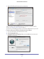
Use NETGEAR genie after Installation
When you first set up your router, NETGEAR genie automatically starts when you launch an
Internet browser on a computer that is connected to the router. You can use NETGEAR genie
again if you want to view or change settings for the router.
1. Launch your browser from a computer or wireless device that is connected to the router.
2. Enter http://www.routerlogin.net in the web browser address bar.
A login window displays.
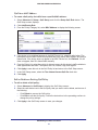
admin
********
3. Enter admin for the router user name and password for the router password, both in
lowercase letters.
Note: The router user name and password are different from the user name
and password for logging in to your Internet connection. See Types of Logins
and Access on page 21 for more information.
Upgrade the Firmware
When you set up your router and are connected to the Internet, the router automatically
checks for you to see if newer firmware is available. If it is, a message is displayed on the top
of the screen. See Upgrade the Modem Router Firmware on page 82 for more information
about upgrading firmware.
Click the message when it shows up, and click Yes to upgrade the router with the latest
firmware. After the upgrade, the router restarts automatically.
CAUTION:
Do not try to go online, turn off the router, shut down the computer, or do
anything else to the router until the router finishes restarting and the Power
LED has stopped blinking for several seconds.
Getting Started with NETGEAR genie
22
CENTRIA WNDR4700/WNDR4720
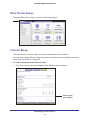
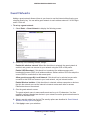
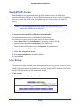
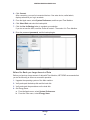
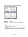
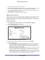
Dashboard (Basic Home Screen)
The Basic Home screen has a dashboard that lets you see the status of your Internet
connection and network at a glance. You can click any of the six sections of the dashboard to
view more detailed information. The left column has the menus, and at the top, there is an
Advanced tab that you can use to access more menus and screens.
Language
Menus
(Click the
Advanced
tab to view
more)
Dashboard
(Click to
view details)
Help
Figure 5. Basic Home screen with dashboard, language, and online help
•
Home. This dashboard screen displays when you log in to the router.
•
Internet. Set, update, and check the ISP settings of your router.
•
Wireless. View or change the wireless settings for your router.
•
Attached Devices. View the devices connected to your network.
•
Parental Controls. Download and set up parental controls to prevent objectionable
content from reaching your computers.
•
ReadySHARE. Manage storage on the internal hard disk drive (HDD) and USB devices
that you connect to the router USB drive.
•
Guest Network. Set up a guest network to allow visitors to use your router’s Internet
connection.
•
Advanced tab. Set the router up for unique situations such as when remote access by IP
or by domain name from the Internet is needed. See Chapter 9, Advanced Settings. You
need a solid understanding of networking protocols to use this tab.
•
Help & Support. Visit the NETGEAR support site to get information, help, and product
documentation. These links work once you have an Internet connection.
Getting Started with NETGEAR genie
23
CENTRIA WNDR4700/WNDR4720
Join Your Wireless Network
You can use the manual or the WPS method to join your wireless network. See Guest
Networks on page 36 for instructions about how to set up a guest network.
Manual Method
With the manual method, you choose the network that you want and enter its password to
connect.
To connect manually:
1. On your computer or wireless device, open the software that manages your wireless
connections. The wireless software scans for all wireless networks in your area.
2. Look for your network and select it.
The preset SSID (wireless network name) and preset WiFi password are on the router
label. If you changed these settings, then look for the network name that you used.
3. Enter the router password and click Connect.
Wi-Fi Protected Setup (WPS) Method
Wi-Fi Protected Setup (WPS) lets you connect to a secure WiFi network without typing its
password. Instead, press a button or enter a PIN. NETGEAR calls WPS Push 'N' Connect.
Some older WiFi equipment is not compatible with WPS. WPS works only with WPA2 or WPA
wireless security.
To use WPS to join the wireless network:
1. Press the WPS button on the router side panel.
2. Within 2 minutes, press the WPS button on your wireless device, or follow the WPS
instructions that came with the device.
The WPS process automatically sets up your wireless computer with the network
password and connects you to the wireless network.
Getting Started with NETGEAR genie
24
CENTRIA WNDR4700/WNDR4720
NETGEAR genie App and Mobile genie App
The genie app is the easy dashboard for managing, monitoring, and repairing your home
network. See the NETGEAR genie App User Manual for details about the genie apps.
Retrieve wireless password
About genie
Language
Menu
Dashboard
(Click to
view
details)
Support
The genie app can help you with the following:
•
Automatically repair common wireless network problems.
•
Have easy access to router features like Live Parental Controls, guest access, Internet
traffic meter, speed test, and more.
The genie mobile app works on your iPhone, iPad, or Android phone:
Phone status
Information about
genie mobile app
and the connected
router
Log in to the router
Search NETGEAR
support
Getting Started with NETGEAR genie
25
3.
NETGEAR genie Basic Settings
Your Internet connection and net work
This chapter contains the following sections:
•
Basic Home Screen
•
Internet Setup
•
Attached Devices
•
Parental Controls
•
ReadySHARE Storage
•
Basic Wireless Settings
•
Guest Networks
26
3
CENTRIA WNDR4700/WNDR4720
Basic Home Screen
The genie Basic Home screen is shown in the following figure:
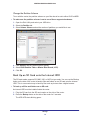
Internet Setup
The Internet Setup screen is where you view or change basic ISP information.
You can use the Setup Wizard to detect the Internet connection and automatically set up the
router. See Setup Wizard on page 39.
To view or change the basic Internet setup:
1. From the Home screen, select Internet. The following screen displays:
Scroll to view
more settings
NETGEAR genie Basic Settings
27
CENTRIA WNDR4700/WNDR4720
The fields that display in the Internet Setup screen depend on whether your Internet
connection requires a login.
•
Yes. Select the encapsulation method and enter the login name. If you want to
change the login time-out, enter a new value in minutes.
•
No. Enter the account and domain names, only if needed.
2. Enter the settings for the IP address and DNS server. The default settings usually work fine.
If you have problems with your connection, check to make sure that the settings in this
screen match the information from your ISP.
3. Click Apply to save your settings.
4. Click Test to test your Internet connection. If the NETGEAR website does not display within
1 minute, see Chapter 11, Troubleshooting.
Internet Setup Screen Fields
The following descriptions explain all of the possible fields in the Internet Setup screen. The
fields that display in this screen depend on whether tan ISP login is required.
Does Your ISP Require a Login? Answer either yes or no.
These fields display when no login is required:
•
Account Name (if required) Enter the account name that your ISP provided. This might
also be called the host name.
•
Domain Name (if required) Enter the domain name that your ISP provided.
These fields display when your ISP requires a login:
•
Internet Service Provider Encapsulation. ISP types. The choices are PPPoE, PPTP, or
L2TP. If you are not sure, check with your ISP.
•
Login. The login name that your ISP provided. This login name is often an email address.
•
Password. The password that you use to log in to your ISP.
•
Idle Timeout (In minutes). If you want to change the login time-out, enter a new value in
minutes. This setting determines how long the router keeps the Internet connection active
after there is no Internet activity from the LAN. A value of 0 (zero) means never log out.
Internet IP Address.
•
Get Dynamically from ISP. Your ISP uses DHCP to assign your IP address. Your ISP
automatically assigns these addresses.
•
Use Static IP Address. Enter the IP address, IP subnet mask, and the gateway IP
address that your ISP assigned. The gateway is the ISP router to which your router will
connect.
Domain Name Server (DNS) Address. The DNS server is used to look up site addresses
based on their names.
NETGEAR genie Basic Settings
28
CENTRIA WNDR4700/WNDR4720
•
Get Automatically from ISP. Your ISP uses DHCP to assign your DNS servers. Your ISP
automatically assigns this address.
•
Use These DNS Servers. If you know that your ISP requires specific servers, select this
option. Enter the IP address of your ISP’s primary DNS server. If a secondary DNS server
address is available, enter it also.
Router MAC Address. The Ethernet MAC address that the router uses on the Internet port.
Some ISPs register the MAC address of the network interface card in your computer when
your account is first opened. They accept traffic only from the MAC address of that computer.
This feature allows your router to use your computer’s MAC address (this is also called
cloning).
•
Use Default Address. Use the default MAC address.
•
Use Computer MAC Address. The router captures and uses the MAC address of the
computer that you are now using. You have to use the one computer that the ISP allows.
•
Use This MAC Address. Enter the MAC address that you want to use.
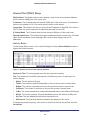
Attached Devices
Use the Attached Device screen to view all computers or devices that are currently
connected to your network.
To go to the Attached Devices screen:
From the Basic Home screen, select Attached Devices to display the following screen:
Wired devices are connected to the router with Ethernet cables. Wireless devices have
joined the wireless network.
•
# (number). The order in which the device joined the network.
•
IP Address. The IP address that the router assigned to this device when it joined the
network. This number can change if a device is disconnected and rejoins the network.
•
MAC Address. The unique MAC address for each device does not change. The MAC
address is typically shown on the product label.
•
Device Name. If the device name is known, it is shown here.
You can click Refresh to update this screen.
NETGEAR genie Basic Settings
29
CENTRIA WNDR4700/WNDR4720
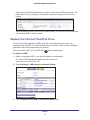
Parental Controls
The first time you select Parental Controls from the Basic Home screen, your browser goes to
the Parental Controls website. You can learn more about Live Parental Controls or download
the application.
To set up Live Parental Controls:
1. Select Parental Controls on the Home (dashboard) screen.
Live Parental Controls uses free OpenDNS accounts. If you do not have one, you can
create one now.
2. Log in to manage Parental Control settings.
3. Click either the Windows Users or Mac Users button.
4. Follow the onscreen instructions to download and install the NETGEAR Live Parental
Controls Management Utility.
NETGEAR genie Basic Settings
30
CENTRIA WNDR4700/WNDR4720
After installation, Live Parental Controls automatically starts.
5. Click Next, read the note, and click Next again to proceed.
You are prompted to log in or create a free account.
6. Select the radio button that applies to you and click Next.
• If you already have an OpenDNS account, leave the Yes radio button selected.
•
If you do not have an OpenDNS account, select the No radio button.
After you log on or create your account, the filtering level screen displays:
NETGEAR genie Basic Settings
31
CENTRIA WNDR4700/WNDR4720
7. Select the radio button for the filtering level that you want and click Next.
8. Click the Take me to the status screen button.
Parental controls are now set up for the router. The dashboard shows Parental Controls as
enabled.
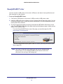
ReadySHARE Storage
You can view information about an internal hard disk drive (HDD) or a USB storage device
that is connected to the router’s USB port here. From the Basic Home screen, select
ReadySHARE to display the USB Storage (Basic Settings) screen:
To work with storage, leave the Basic radio button selected. This screen displays the
following:
•
Network/Device Name. The default is \\readyshare.
•
Available Network Folders. The folders on the HDD or USB device.
NETGEAR genie Basic Settings
32
CENTRIA WNDR4700/WNDR4720
Share Name. You can click the name shown, or you can type it in the address field of
your web browser. If Not Shared is shown, the default share has been deleted and no
other share for the root folder exists. Click the link to change this setting.
Read Access and Write Access. Shows the permissions and access controls on the
network folder: All – no password (the default) allows all users to access the network
folder. The user name (account name) for All – no password is guest. The password for
admin is the same one that you use to log in to the router. By default, it is password.
Folder Name. Full path of the network folder.
Volume Name. Volume name from the storage device (either USB drive or HDD).
Total Space and Free Space. Shows the current utilization of the storage device.
•
Edit. Click the Edit button to edit the Available Network Folders settings.
•
Safely Remove USB or Internal Hard Disk Drive. Safely remove the USB device
attached to your router.
You can click Refresh to update this screen. For more information about USB storage, see
Chapter 5, Storage.
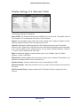
Basic Wireless Settings
The Wireless Settings screen lets you view or configure the wireless network setup.
The CENTRIA comes with preset security. This means that the Wi-Fi network name (SSID),
network key (password), and security option (encryption protocol) are preset in the factory.
You can find the preset SSID and password on the bottom of the unit.
Note: The preset SSID and password are uniquely generated for every
device to protect and maximize your wireless security.
To view or change basic wireless settings:
NETGEAR recommends that you do not change your preset security settings. If you change
your preset security settings, make a note of the new settings and store it in a safe place
where you can easily find it.
If you use a wireless computer to change the wireless network name (SSID) or other wireless
security settings, you are disconnected when you click Apply. To avoid this problem, use a
computer with a wired connection to access the router.
NETGEAR genie Basic Settings
33
CENTRIA WNDR4700/WNDR4720
1. Select Basic > Wireless to display the Wireless Settings screen.
The screen sections, settings, and procedures are explained in the following sections.
2. Make any changes that are needed and click Apply to save your settings.
3. Set up and test your wireless devices and computers to make sure that they can connect
wirelessly. If they do not, check the following:
• Is your wireless device or computer connected to your network or another wireless
network in your area? Some wireless devices automatically connect to the first open
network (without wireless security) that they discover.
•
Does your wireless device or computer show up on the Attached Devices screen? If it
does, then it is connected to the network.
•
If you are not sure what the network name (SSID) or password is, look on the label on
the bottom of your router.
Wireless Settings Screen Fields
Region Selection
The location where the router is used. Select from the countries in the list. In the United
States, the region is fixed to United States and is not changeable.
Wireless Network (2.4 GHz b/g/n and 5 GHz)
The b/g/n notation references the 802.11 standards of conformance for the 2.4 GHz radio
frequency.
Enable Wireless Isolation. If this check box is selected, wireless computers or devices that
join the network can use the Internet but cannot access each other or access Ethernet
devices on the network.
NETGEAR genie Basic Settings
34
CENTRIA WNDR4700/WNDR4720
Enable SSID Broadcast. This setting allows the router to broadcast its SSID so wireless
stations can see this wireless name (SSID) in their scanned network lists. This check box is
selected by default. To turn off the SSID broadcast, clear the Enable SSID Broadcast check
box and click Apply.
Name (SSID). The SSID is also known as the wireless network name. Enter a 32-character
(maximum) name in this field. This field is case-sensitive. The default SSID is randomly
generated, and NETGEAR strongly recommends that you do not change this setting.
Channel. This setting is the wireless channel the gateway uses. Enter a value from 1 through
13. For products in the North America market, only channels 1 through 11 can be operated.
Do not change the channel unless you experience interference (shown by lost connections or
slow data transfers). If this happens, experiment with different channels to see which is the
best.
Mode. Up to 150 Mbps is the default and allows 802.11n and 802.11g wireless devices to join
the network. g & b supports up to 54 Mbps. Up to 65 Mbps supports up to 65 Mbps.
Security Options Settings
The Security Options section of the Wireless Settings screen lets you change the security
option and passphrase. NETGEAR recommends that you do not change the security option
or passphrase, but if you want to change these settings, this section explains how. Do not
disable security.
Change WPA Security Option and Password
You can change the security settings for your router. If you do so, then write down the new
settings and store them in a secure place for future reference.
To change the WPA settings:
1. On the Wireless Settings screen, under Security Options, select the WPA option you
want.
2. In the Passphrase field that displays when you select a WPA security option, enter the
network passphrase (password) that you want to use. It is a text string from 8 to 63
characters.
NETGEAR genie Basic Settings
35
CENTRIA WNDR4700/WNDR4720
Guest Networks
Adding a guest network allows visitors at your home to use the Internet without having your
wireless security key. You can add a guest network to each wireless network: 2.4 GHz b/g/n
and 5.0 GHz a/n
To set up a guest network:
1. Select Basic > Guest Network to display the following screen:
2. Select any of the following wireless settings:
Enable this wireless network. When this check box is selected, the guest network is
enabled, and guests can connect to your network using the SSID of this profile.
Enable SSID Broadcast. If this check box is selected, the wireless access point
broadcasts its name (SSID) to all wireless stations. Stations with no SSID can adopt the
correct SSID for connections to this access point.
Allow guest to access My Local Network. If this check box is selected, anyone who
connects to this SSID has access to your local network, not just Internet access.
Enable Wireless Isolation. If this check box is selected, wireless computers or devices
that join the network can use the Internet but cannot access each other or access
Ethernet devices on the network.
3. Give the guest network a name.
The guest network name is case-sensitive and can be up to 32 characters. You then
manually configure the wireless devices in your network to use the guest network name in
addition to the main SSID.
4. Select a security option from the list. The security options are described in Guest Network
Wireless Security Options on page 37.
5. Click Apply to save your selections.
NETGEAR genie Basic Settings
36
CENTRIA WNDR4700/WNDR4720
Guest Network Wireless Security Options
A security option is the type of security protocol applied to your wireless network. The
security protocol in force encrypts data transmissions and ensures that only trusted devices
receive authorization to connect to your network. Wi-Fi Protected Access (WPA) has several
options including pre-shared key (PSK) encryption.
This section presents an overview of the security options and provides guidance on when to
use which option. It is also possible to set up a guest network without wireless security.
NETGEAR does not recommend this.
WPA Encryption
WPA encryption is built into all hardware that has the Wi-Fi-certified seal. This seal means
that the product is authorized by the Wi-Fi Alliance (http://www.wi-fi.org/) because it complies
with the worldwide single standard for high-speed wireless local area networking.
WPA uses a password for authentication and to generate the initial data encryption keys.
Then it dynamically varies the encryption key. WPA-PSK uses Temporal Key Integrity
Protocol (TKIP) data encryption, implements most of the IEEE 802.11i standard, and works
with all wireless network interface cards, but not all wireless access points.
WPA2-PSK is stronger than WPA-PSK. It is advertised to be theoretically indecipherable due
to the greater degree of randomness in encryption keys that it generates. WPA2-PSK gets
higher speed because it is usually implemented through hardware, while WPA-PSK is usually
implemented through software. WPA2-PSK uses a password to authenticate and generate
the initial data encryption keys. Then it dynamically varies the encryption key.
WPS-PSK + WPA2-PSK Mixed Mode can provide broader support for all wireless clients.
WPA2-PSK clients get higher speed and security, and WPA-PSK clients get decent speed
and security. For help with WPA settings on your wireless computer or device, see the
instructions that came with your product.
NETGEAR genie Basic Settings
37
4.
NETGEAR genie Advanced Home
Spe cif ying custom set ti ngs
This chapter contains the following sections:
•
NETGEAR genie Advanced Home Screen
•
Setup Wizard
•
WPS Wizard
•
Setup Menu
•
WAN Setup
•
LAN Setup
•
Quality of Service (QoS) Setup
Some selections on the Advanced Home screen are described in separate chapters:
•
Storage. See Chapter 5, Storage.
•
Security. See Chapter 7, Security.
•
Administration. See Chapter 8, Administration.
•
Advanced Setup. See Chapter 9, Advanced Settings.
38
4
CENTRIA WNDR4700/WNDR4720
NETGEAR genie Advanced Home Screen
The genie Advanced Home dashboard presents status information. The content is the same
as what is on the Router Status screen available from the Administration menu. The genie
Advanced Home screen is shown in the following figure:
This screen is
also displayed
through the
Administration
menu.
Setup Wizard
You can use the Setup Wizard to detect your Internet settings and automatically set up your
router. The Setup Wizard is not the same as the genie screens that display the first time you
connect to your router to set it up.
To use the Setup Wizard:
1. Select Advanced > Setup Wizard to display the following screen:
2. Select either Yes or No, I want to configure the router myself. If you select No, you are
taken to the Internet Setup screen (see Internet Setup on page 26).
NETGEAR genie Advanced Home
39
CENTRIA WNDR4700/WNDR4720
3. Select Yes and click Next.
The Setup Wizard searches your Internet connection for servers and protocols to
determine your ISP configuration. The following screen displays:
WPS Wizard
The WPS Wizard helps you add a WPS-capable client device (a wireless device or computer)
to your network. On the client device, either press its WPS button or locate its WPS PIN.
To use the WPS Wizard:
1. Select Advanced > WPS Wizard.
2. Click Next. The following screen lets you select the method for adding the WPS client (a
wireless device or computer).
You can use either the push button or PIN method.
3. Select either Push Button or PIN Number.
•
To use the push button method, either click the WPS button on this screen, or press
the WPS button on the side of the router. Within 2 minutes, go to the wireless client
and press its WPS button to join the network without entering a password.
•
To use the PIN method, select the PIN Number radio button, enter the client security
PIN, and click Next.
NETGEAR genie Advanced Home
40
CENTRIA WNDR4700/WNDR4720
Within 2 minutes, go to the client device and use its WPS software to join the network
without entering a password.
The router attempts to add the WPS-capable device. The WPS LED
on the front of
the router blinks green. When the router establishes a WPS connection, the LED is solid
green, and the router WPS screen displays a confirmation message.
4. Repeat Step 2 and Step 3 to add another WPS client to your network.
Setup Menu
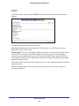
Select Advanced > Setup to display the Setup menu. The following selections are available:
•
Internet Setup. Go to the same Internet Setup screen that you can access from the
dashboard on the Basic Home screen. See Internet Setup on page 26.
•
Wireless Setup. Go to the same Wireless Settings screen that you can access from the
dashboard on the Basic Home screen. See Basic Wireless Settings on page 33.
•
Guest Network. This selection is a shortcut to the same Guest Network screen that you
can access from the dashboard on the Basic Home screen. See Guest Networks on
page 36.
•
WAN Setup. Internet (WAN) setup. See WAN Setup on page 42.
•
LAN Setup. Local area network (LAN) setup. See LAN Setup on page 45.
•
QoS Setup. Quality of Service (QoS) setup. See Quality of Service (QoS) Setup on
page 48.
NETGEAR genie Advanced Home
41
CENTRIA WNDR4700/WNDR4720
WAN Setup
The WAN Setup screen lets you configure a DMZ (demilitarized zone) server, change the
maximum transmit unit (MTU) size, and enable the router to respond to a ping on the WAN
(Internet) port.
To view or change the WAN settings:
Select Advanced > Setup > WAN Setup
The following settings are available:
•
Disable Port Scan and DoS Protection. DoS protection protects your LAN against
denial of service attacks such as Syn flood, Smurf Attack, Ping of Death, Teardrop Attack,
UDP Flood, ARP Attack, Spoofing ICMP, Null Scan, and many others. This should be
disabled only in special circumstances.
•
Default DMZ Server. This feature is sometimes helpful when you are playing online
games or videoconferencing. Be careful when using this feature because it makes the
firewall security less effective. See the following section, Default DMZ Server, for more
details.
•
Respond to Ping on Internet Port. If you want the router to respond to a ping from the
Internet, select this check box. Use this setting only as a diagnostic tool because it allows
your router to be discovered. Do not select this check box unless you have a specific
reason.
•
Disable IGMP Proxying. The IGPM Proxying feature lets a LAN computer receive the
multicast traffic directed to it from the Internet. Selecting this check box prevents this from
occurring.
•
MTU Size (in bytes). The normal MTU (maximum transmit unit) value for most Ethernet
networks is 1500 bytes, or 1492 bytes for PPPoE connections. For some ISPs, you might
need to reduce the MTU. This is rarely required. You should change the setting in this
field only if you are sure that it is necessary for your ISP connection. See Change the
MTU Size on page 44.
•
NAT Filtering. Network Address Translation (NAT) determines how the router processes
inbound traffic. Secured NAT provides a secured firewall to protect the computers on the
NETGEAR genie Advanced Home
42
CENTRIA WNDR4700/WNDR4720
LAN from attacks from the Internet, but might prevent some Internet games,
point-to-point applications, or multimedia applications from functioning. Open NAT
provides a much less secured firewall, but allows almost all Internet applications to
function.
•
Disable SIP ALG. The Session Initiation Protocol (SIP) Application Level Gateway (ALG)
is enabled by default to optimize VoIP phone calls that use the SIP. The Disable SIP ALG
check box allows you to disable the SIP ALG. Disabling the SIP ALG might be useful
when running certain applications.
Default DMZ Server
The default DMZ server feature is helpful when you are using some online games and
videoconferencing applications that are incompatible with Network Address Translation
(NAT). The router recognizes some of these applications and works correctly with them, but
there are other applications that might not function well. In some cases, one local computer
can run the application correctly if that computer’s IP address is entered as the default DMZ
server.
WARNING!
DMZ servers pose a security risk. A computer designated as the
default DMZ server loses much of the protection of the firewall
and is exposed to exploits from the Internet. If compromised, the
DMZ server computer can be used to attack other computers on
your network.
The router usually detects and discards incoming traffic from the Internet that is not a
response to local computers or a service that you set up in the Port Forwarding/Port
Triggering screen. Instead of discarding this traffic, you can have the router forward the traffic
to one computer on your network. This computer is called the default DMZ server.
To set up a default DMZ server:
1. On the WAN Setup screen, select the Default DMZ Server check box.
2. Type the IP address.
3. Click Apply.
NETGEAR genie Advanced Home
43
CENTRIA WNDR4700/WNDR4720
Change the MTU Size
The maximum transmission unit (MTU) is the largest data packet a network device transmits.
When one network device communicates across the Internet with another, the data packets
travel through many devices along the way. If a device in the data path has a lower MTU
setting than the other devices, the data packets are split or “fragmented” to accommodate the
device with the smallest MTU.
The best MTU setting for NETGEAR equipment is often just the default value. In some
situations, changing the value fixes one problem but causes another. Leave the MTU
unchanged unless one of these situations occurs:
•
You have problems connecting to your ISP or other Internet service, and the technical
support of either the ISP or NETGEAR recommends changing the MTU setting. These
web-based applications might require an MTU change:
-
A secure website that does not open, or displays only part of a web page
-
Yahoo email
-
MSN portal
-
America Online’s DSL service
•
You use VPN and have severe performance problems.
•
You used a program to optimize MTU for performance reasons, and now you have
connectivity or performance problems.
Note: An incorrect MTU setting can cause Internet communication
problems. For example, you might not be able to access certain
websites, frames within websites, secure login pages, or FTP or
POP servers.
If you suspect an MTU problem, a common solution is to change the MTU to 1400. If you are
willing to experiment, you can gradually reduce the MTU from the maximum value of 1500
until the problem goes away. The following table describes common MTU sizes and
applications.
Table 3. Common MTU sizes
MTU
Application
1500
The largest Ethernet packet size and the default value. This setting is typical for
connections that do not use PPPoE or VPN, and is the default value for NETGEAR
routers, adapters, and switches.
1492
Used in PPPoE environments.
1472
Maximum size to use for pinging. (Larger packets are fragmented.)
1468
Used in some DHCP environments.
NETGEAR genie Advanced Home
44
CENTRIA WNDR4700/WNDR4720
Table 3. Common MTU sizes (Continued)
MTU
Application
1460
Usable by AOL if you do not have large email attachments..
1436
Used in PPTP environments or with VPN.
1400
Maximum size for AOL DSL.
576
Typical value to connect to dial-up ISPs.
To change the MTU size:
1. Select Advanced > Setup > WAN Setup.
2. In the MTU Size field, enter a value from 64 to 1500.
3. Click Apply to save the settings.
LAN Setup
The LAN Setup screen allows configuration of LAN IP services such as Dynamic Host
Configuration Protocol (DHCP) and Routing Information Protocol (RIP).
The router is shipped preconfigured to use private IP addresses on the LAN side and to act
as a DHCP server. The router’s default LAN IP configuration is:
•
LAN IP address. 192.168.1.1
•
Subnet mask. 255.255.255.0
These addresses are part of the designated private address range for use in private networks
and are suitable for most applications. If your network requires a different IP addressing
scheme, you can change these settings in the LAN Setup screen.
To change the LAN settings:
Note: If you change the LAN IP address of the router, you are
disconnected. To use the router menus, you must use a browser to
connect to the new IP address and log in again.
NETGEAR genie Advanced Home
45
CENTRIA WNDR4700/WNDR4720
1. Select Advanced > Setup > LAN Setup to display the following screen:
2. Enter the settings that you want to customize. These settings are described in the following
section, LAN Setup Screen Settings.
3. Click Apply to save your changes.
LAN Setup Screen Settings
LAN TCP/IP Setup
•
IP Address. The LAN IP address of the router.
•
IP Subnet Mask. The LAN subnet mask of the router. Combined with the IP address, the
IP subnet mask allows a device to know which other addresses are local to it, and which
addresses have to be reached through a gateway or router.
•
RIP Direction. Router Information Protocol (RIP) allows a router to exchange routing
information with other routers. This setting controls how the router sends and receives
RIP packets. Both is the default setting. With the Both or Out Only setting, the router
broadcasts its routing table periodically. With the Both or In Only setting, the router
incorporates the RIP information that it receives.
•
RIP Version. This setting controls the format and the broadcasting method of the RIP
packets that the router sends. It recognizes both formats when receiving. By default, the
RIP function is disabled.
RIP-1 is universally supported. It is adequate for most networks, unless you have an
unusual network setup.
RIP-2 carries more information. Both RIP-2B and RIP-2M send the routing data in RIP-2
format. RIP-2B uses subnet broadcasting. RIP-2M uses multicasting.
NETGEAR genie Advanced Home
46
CENTRIA WNDR4700/WNDR4720
Use Router as a DHCP Server
Usually, this check box is selected so that the router functions as a Dynamic Host
Configuration Protocol (DHCP) server.
•
Starting IP Address. Specify the start of the range for the pool of IP addresses in the
same subnet as the router.
•
Ending IP Address. Specify the end of the range for the pool of IP addresses in the
same subnet as the router.
Address Reservation
When you specify a reserved IP address for a computer on the LAN, that computer receives
the same IP address each time it accesses the router’s DHCP server. Assign reserved IP
addresses to servers that require permanent IP settings. See Address Reservation on
page 48.
Use the Router as a DHCP Server
By default, the router acts as a DHCP server. The router assigns IP, DNS server, and default
gateway addresses to all computers connected to the LAN. The assigned default gateway
address is the LAN address of the router. The router assigns IP addresses to the attached
computers from a pool of addresses specified in this screen. Each pool address is tested
before it is assigned to avoid duplicate addresses on the LAN. For most applications, the
default DHCP and TCP/IP settings of the router are satisfactory.
You can specify the pool of IP addresses that can be assigned by setting the starting IP
address and ending IP address. These addresses should be part of the same IP address
subnet as the router’s LAN IP address. Using the default addressing scheme, define a range
between 192.168.1.2 and 192.168.1.254, although you might want to save part of the range
for devices with fixed addresses.
The router delivers the following parameters to any LAN device that requests DHCP:
•
An IP address from the range you have defined
•
Subnet mask
•
Gateway IP address (the router’s LAN IP address)
•
Primary DNS server (if you entered a primary DNS address in the Internet Setup screen;
otherwise, the router’s LAN IP address)
•
Secondary DNS server (if you entered a secondary DNS address in the Internet Setup
screen)
To use another device on your network as the DHCP server, or to specify the network
settings of all of your computers, clear the Use Router as DHCP Server check box and click
Apply. Otherwise, leave this check box selected. If this service is not enabled and no other
DHCP server is available on your network, set your computers’ IP addresses manually so
that they can access the router.
NETGEAR genie Advanced Home
47
CENTRIA WNDR4700/WNDR4720
Address Reservation
When you specify a reserved IP address for a computer on the LAN, that computer always
receives the same IP address each time it accesses the router’s DHCP server. Reserved IP
addresses should be assigned to computers or servers that require permanent IP settings.
To reserve an IP address:
1. In the Address Reservation section of the screen, click the Add button.
2. In the IP Address field, type the IP address to assign to the computer or server. (Choose an
IP address from the router’s LAN subnet, such as 192.168.1.x.)
3. Type the MAC address of the computer or server.
Tip: If the computer is already on your network, you can copy its MAC
address from the Attached Devices screen and paste it here.
4. Click Apply to enter the reserved address into the table.
The reserved address is not assigned until the next time the computer contacts the
router’s DHCP server. Reboot the computer, or access its IP configuration and force a
DHCP release and renew.
To edit or delete a reserved address entry, select the radio button next to the reserved
address you want to edit or delete. Then click Edit or Delete.
Quality of Service (QoS) Setup
QoS is an advanced feature that can be used to prioritize some types of traffic ahead of
others. The CENTRIA can provide QoS prioritization over the wireless link and on the
Internet connection.
To configure QoS:
Select Advanced > Setup > QoS Setup to display the following screen:
NETGEAR genie Advanced Home
48
CENTRIA WNDR4700/WNDR4720
Enable WMM QoS for Wireless Multimedia Applications
The CENTRIA supports Wi-Fi Multimedia Quality of Service (WMM QoS) to prioritize wireless
voice and video traffic over the wireless link. WMM QoS provides prioritization of wireless
data packets from different applications based on four access categories: voice, video, best
effort, and background. For an application to receive the benefits of WMM QoS, both it and
the client running that application have to have WMM enabled. Legacy applications that do
not support WMM and applications that do not require QoS, are assigned to the best effort
category, which receives a lower priority than voice and video.
WMM QoS is enabled by default. You can disable it in the QoS Setup screen by clearing the
Enable WMM check box and clicking Apply.
Set Up QoS for Internet Access
You can give prioritized Internet access to the following types of traffic:
•
Specific applications
•
Specific online games
•
Individual Ethernet LAN ports of the router
•
A specific device by MAC address
To specify prioritization of traffic, create a policy for the type of traffic and add the policy to the
QoS Policy table in the QoS Setup screen. For convenience, the QoS Policy table lists many
common applications and online games that can benefit from QoS handling.
QoS for Applications and Online Gaming
To create a QoS policy for applications and online games:
1. In the QoS Setup screen, select the Turn Internet Access QoS On check box.
2. Click the Setup QoS Rule button to see the QoS Priority Rule list.
NETGEAR genie Advanced Home
49
CENTRIA WNDR4700/WNDR4720
You can edit or delete a rule by selecting its radio button and clicking either the Edit or
Delete button. You can also delete all the rules by clicking the Delete All button.
3. To add a priority rule, scroll down to the bottom of the QoS Setup screen and click Add
Priority Rule to display the following screen:
4. In the QoS Policy for field, type the name of the application or game.
5. In the Priority Category list, select either Applications or Online Gaming. A list of
applications or games displays.
6. You can select an existing item from the list, or you can scroll and select Add a New
Application or Add a New Game, as applicable.
7. If prompted, in the Connection Type list, select either TCP, UDP, or both (TCP/UDP). Specify
the port number or range of port numbers that the application or game uses.
8. From the Priority list, select the priority for Internet access for this traffic relative to other
applications and traffic. The options are Low, Normal, High, and Highest.
9. Click Apply to save this rule to the QoS Policy list and return to the QoS Setup screen.
QoS for a Router LAN Port
To create a QoS policy for a device connected to one of the router’s LAN ports:
1. Select Advanced > Setup > QoS Setup to display the QoS Setup screen.
2. Select the Turn Internet Access QoS On check box.
3. Click the Setup QoS Rule button.
4. Click the Add Priority Rule button.
5. From the Priority Category list, select Ethernet LAN Port, as shown in the following figure:
6. From the LAN port list, select the LAN port.
7. From the Priority list, select the priority for Internet access for this port’s traffic relative to
other applications. The options are Low, Normal, High, and Highest.
8. Click Apply to save this rule to the QoS Policy list and return to the QoS Setup screen.
9. In the QoS Setup screen, click Apply.
NETGEAR genie Advanced Home
50
CENTRIA WNDR4700/WNDR4720
QoS for a MAC Address
To create a QoS policy for traffic from a specific MAC address:
1. Select Advanced > Setup > QoS Setup, and click the Setup QoS Rule button. The
QoS Setup screen displays.
2. Click Add Priority Rule.
3. From the Priority Category list, select MAC Address to display the following screen:
4. If the device to be prioritized appears in the MAC Device List, select its radio button. The
information from the MAC Device List populates the policy name, MAC Address, and Device
Name fields. If the device does not appear in the MAC Device List, click Refresh. If it still
does not appear, then fill in these fields manually.
5. From the Priority list, select the priority for Internet access for this device’s traffic reelative to
other applications and traffic. The options are Low, Normal, High, and Highest.
6. Click Apply to save this rule to the QoS Policy list and return to the QoS Setup screen.
7. In the QoS Setup screen, select the Turn Internet Access QoS On check box.
8. Click Apply.
Edit or Delete an Existing QoS Policy
To edit or delete a QoS policy:
1. Select Advanced > QoS Setup to display the QoS Setup screen.
2. Select the radio button next to the QoS policy that you want to edit or delete, and do one of
the following:
• Click Delete to remove the QoS policy.
•
Click Edit to edit the QoS policy. Follow the instructions in the preceding sections to
change the policy settings.
3. Click Apply in the QoS Setup screen to save your changes.
NETGEAR genie Advanced Home
51
5.
Storage
Ac c essing a nd configuring an HD D or US B
storage drive
5
This chapter describes how to access and configure a storage drive attached to your router. The
USB port on the router can be used to connect only USB storage devices like flash drives or hard
drives, or a printer. Do not connect computers, USB modems, CD drives, or DVD drives to the
router USB port.
This chapter contains the following sections:
•
ReadySHARE Access
•
User Setup
•
File-Sharing Scenarios
•
Storage Basic Settings
•
Storage Advanced Settings
•
Safely Remove a USB or Internal Hard Drive
•
Media Server
•
Specify Approved USB Devices
•
Connect to the USB Drive from a Remote Computer
•
ReadySHARE Cloud
•
Back Up Your Computers
•
Replace the Internal Hard Disk Drive
•
Format the HDD
For information about using the ReadySHARE Printer feature, see Chapter 6, ReadySHARE
Printer.
For more information about ReadySHARE features, see www.netgear.com/readyshare.
52
CENTRIA WNDR4700/WNDR4720
ReadySHARE Access
ReadySHARE lets you access and share the HDD inside the router or a USB drive
connected the router USB port. (If your USB device has special drivers, it is not compatible.)
When you connect the USB device, it might take up to 2 minutes before it is ready for
sharing.
Note: If your USB device has a power supply, you must use it when you
connect the USB device to the router.
To access the internal HDD or USB device from Windows:
The readyshareconnect.exe file is available to download here:
www.netgear.com/readyshare. You can use any of these methods:
•
Select Start > Run. Enter \\readyshare in the dialog box and click OK.
•
Open a browser and enter \\readyshare in the address bar.
•
Open My Network Places and enter \\readyshare in the address bar.
To access the internal HDD or USB device from a Mac:
1. Select Go > Connect to Server.
2. Enter smb://readyshare as the server address.
3. Click Connect.
User Setup
The router comes with the admin user name that allows you to log in to the router to view its
settings and change them. In the User Setup screen, you can add up to four users in addition
to admin. Each user name and password can contain printable ASCII characters (ASCII 0x20
through 0x7E) and can be up to 60 characters in length.
To add a user:
1. Select Advanced > Storage > User Setup.
Storage
53
CENTRIA WNDR4700/WNDR4720
2. Click Add.
3. In the User Name field, type a name.
4. Type the password in the Password field and in the Re-enter Password field to confirm it.
5. Click the Add button when finished.
File-Sharing Scenarios
You can share files on the USB drive for a wide variety of business and recreational
purposes. The files can be any computer, Mac, or Linux file type including text files, Word,
PowerPoint, Excel, MP3, pictures, and multimedia files. USB drive applications include:
•
Sharing multimedia with friends and family such as MP3 files, pictures, and other
multimedia with local and remote users.
•
Sharing resources on your network. You can store files in a central location so that you do
not have to power up a computer to perform local sharing. In addition, you can share files
between Macintosh, Linux, and Windows computers by using the USB drive as a
go-between across the systems.
•
Sharing files such as Word documents, PowerPoint presentations, and text files with
remote users.
A few common uses are described in the following sections.
Share Photos
You can create your own central storage location for photos and multimedia. This method
eliminates the need to log in to (and pay for) an external photo-sharing site.
To share files with your friends and family:
1. Insert your USB drive into the USB port on the router either directly or with a USB cable.
Computers on your local area network (LAN) can automatically access this USB drive
using a web browser or Microsoft Networking.
2. If you want to specify read-only access or to allow access from the Internet, see Storage
Advanced Settings on page 58.
Storage
54
CENTRIA WNDR4700/WNDR4720
Store Files in a Central Location for Printing
This scenario is for a family that has one high-quality color printer directly attached to a
computer, but not shared on the local area network (LAN). This family does not have a print
server.
•
One family member has photos on a Macintosh computer that she wants to print.
•
The photo-capable color printer is directly attached to a PC, but not shared on the
network.
•
The Mac and PC are not visible to each other on the network.
To print photos from a Mac on the printer attached to a PC:
1. On the Mac, access the USB drive by typing \\readyshare in the address field of a web
browser. Then copy the photos to the USB drive.
2. On the PC, use a web browser or Microsoft Networking to copy the files from the USB drive
to the PC. Then print the files.
Share Large Files over the Internet
Sending files that are larger than 5 MB can pose a problem for many email systems. The
router allows you to share large files such as PowerPoint presentations or .zip files over the
Internet. FTP can be used to easily download shared files from the router.
Sharing files with a remote colleague involves the following considerations:
•
There are three kinds of accounts: admin, guest, and user accounts. The password for
admin is the same one that you use to access the router. By default, it is password. The
guest user account has no password. You specify the passwords for user accounts in the
User Setup screen (User Setup on page 53).
•
On the FTP site, the person receiving the files uses the guest user account and enters the
password. (FTP requires that you type something in the password field.)
•
Be sure to select the FTP (via Internet) check box in the USB Storage (Advanced
Settings) screen. This option supports both downloading and uploading of files.
You can enable the HTTP (via Internet) option on the USB Storage (Advanced Settings)
screen to share large files. This option supports downloading files only.
Storage
55
CENTRIA WNDR4700/WNDR4720
Storage Basic Settings
You can view or edit basic settings for an internal hard disk drive (HDD) in the router and a
USB storage device attached to your router.
To go to Storage Basic Settings:
Select Basic > ReadySHARE.
By default, the HDD and USB storage device are available to all computers on your local
area network (LAN).
The ReadySHARE print feature allows you to share a printer that you connect to the USB
port on your router. To use the ReadySHARE print feature on a Windows computer, you need
to use the NETGEAR USB Control Center utility. For information about this feature, see
Chapter 6, ReadySHARE Printer.
To access your HDD or USB device:
1. Click the network device name or the share name in your computer’s network folders
list.
2. For SMB://readyshare, click Connect.
Note: If you logged in to the router before you connected your USB device,
you might not see your USB device in the router screens. If this
happens, log out and then log back in.
Storage
56
CENTRIA WNDR4700/WNDR4720
Add or Edit a Network Folder
1. You can access this feature by selecting Basic > ReadySHARE, and clicking Edit, or
selecting Advanced > USB Storage > Advanced Settings.
2. Specify the changes that you want to make:
• To add a folder, click Create Network Folder.
•
To edit a folder, select its radio button and then click Edit.
3. You can use this screen to select a folder, change the share name, or change the read
access or write access from All – no password to admin.
The user name (account name) for All – no password is guest. The password for admin is
the same one that is used to log in to the router. By default, it is password.
4. Click Apply for your changes to take effect.
Storage
57
CENTRIA WNDR4700/WNDR4720
Storage Advanced Settings
You can set up the device name, workgroups, and network folders for your USB device.
To go to storage advances settings:
On the USB Settings screen, click the Edit button to display the following screen:
You can use this screen to specify access to the USB storage device.
•
Network Device Name. The default is readyshare. This is the name used to access the
USB device connected to the router.
•
Workgroup. If you are using a Windows workgroup rather than a domain, the workgroup
name is displayed here. The name works only in an operating system that supports
NetBIOS, such as Microsoft Windows.
•
Access Method. The access methods are described here.
Network Connection. Enabled by default, this connection allows all users on the LAN to
have access to the USB drive.
HTTP. Enabled by default. You can type http://readyshare.routerlogin.net/shares to
access the USB drive.
HTTP (via Internet). Disabled by default. If you enable this setting, remote users can
type http://<public IP address/shares> (for example, http://1.1.10.102/shares) or a
URL domain name to access the USB drive over the Internet. This setting supports file
uploading only.
FTP. Disabled by default.
FTP (via Internet). Disabled by default. If you enable this setting, remote users can
access the USB drive through FTP over the Internet. This setting supports both
downloading and uploading of files.
Storage
58
CENTRIA WNDR4700/WNDR4720
Available Network Folders
You might need to scroll down to view this section of the screen:
•
Share Name. If only one device is connected, the default share name is USB_Storage.
You can click the name shown, or you can type it in the address field of your web browser.
If Not Shared is shown, the default share has been deleted and no other share for the
root folder exists. Click the link to change this setting.
•
Read Access and Write Access. Shows the permissions and access controls on the
network folder: All - no password (the default) allows all users to access the network
folder. The password for admin is the same one that you use to log in to the router.
•
Folder Name. Full path of the network folder.
•
Volume Name. Volume name from the storage device (either USB drive or HDD).
•
Total Space and Free Space. Shows the current utilization of the storage device.
•
S.M.A.R.T. This information is for advanced users. Click the click here link to display
S.M.A.R.T information of the internal HDD.
•
Format Internal Disk. You click this button to format the internal hard disk drive. This
erases all data on the drive. When you click Format Internal Disk, you are asked to
confirm before any data is erased. For more information about formatting the internal
hard disk drive, see See Format the HDD on page 73.
Safely Remove a USB or Internal Hard Drive
To remove a USB device or internal hard disk drive (HDD) safely, select Storage > Basic
Settings, and click the Safely Remove USB or Internal Hard Drive button. This takes the
drive offline.
Storage
59
CENTRIA WNDR4700/WNDR4720
Media Server
By default, the router is set up to act as a ReadyDLNA media server. This setting lets you
view movies and photos on DLNA/UPnP AV–compliant media players, such as Xbox360,
Playstation, and NETGEAR’s Digital Entertainer Live.
To view these settings, select Advanced > USB Storage > Media Server to display the
following screen:
By default the Enable Media Server check box and the Automatic (when new files are added)
radio button are selected. When these options are selected, the router scans for media files
whenever new files are added to the ReadySHARE USB hard drive.
Specify Approved USB Devices
For more security, you can set up the router to share approved USB devices only. You can
access this feature from the Advanced Setup menu on the Advanced tab.
To set up approved USB devices:
1. Select Advanced > Advanced Setup > USB Settings. The following screen displays.
Storage
60
CENTRIA WNDR4700/WNDR4720
2. Click the Approved Devices button. The USB Drive Approved Devices screen displays:
This screen shows the approved USB devices and the available USB devices. You can
remove or add approved USB devices.
3. To add an approved USB device, select it from the Available USB Devices list, and then click
Add.
4. Select the Allow only approved devices check box.
5. Click Apply so that your change takes effect.
If you want to work with another USB device, first click the Safely Remove USB Device
button for the currently connected USB device. Connect the other USB device and repeat
this process.
Connect to the USB Drive from a Remote Computer
To connect to the USB drive from remote computers with a web browser, use the router’s
Internet port IP address. If you are using Dynamic DNS, you can type the DNS name rather
than the IP address. You can view the router’s Internet IP address from the dashboard on the
Basic Home screen or the Advanced Home screen.
Access the Router’s USB Drive Remotely Using FTP
To connect to the router’s USB drive using a web browser:
1. Connect to the router by typing ftp:// and the Internet port IP address in the address
field of Internet Explorer or Netscape Navigator. For example:
ftp://10.1.65.4
If you are using Dynamic DNS, you can type the DNS name rather than the IP address.
2. Type the account name and password that has access rights to the USB drive. The user
name (account name) for All – no password is guest.
3. The directories of the USB drive that your account has access to display. For example, you
could see: share/partition1/directory1. You can now read and copy files from the USB
directory.
Storage
61
CENTRIA WNDR4700/WNDR4720
ReadySHARE Cloud
ReadySHARE Cloud gives you remote access over the Internet to a USB storage device that
is connected to your router’s USB port.
To enable ReadySHARE Cloud, log in to the router and select ReadySHARE. Follow the
instructions to register your router with the ReadySHARE Cloud server.
Use this feature to invite friends and family members to access the shared contents on the
USB device.
If your friends and family do not have a ReadySHARE Cloud account, they are invited to
create one so they can access the shared contents.
Visit http://readyshare.netgear.com and create an account to make your files and folders
accessible at any time, from anywhere.
In addition to remotely sharing anything stored on the USB device connected to your router,
you can:
•
Control friend and family access to each item stored on the USB device.
•
Invite new users to access the shared contents.
Storage
62
CENTRIA WNDR4700/WNDR4720
Back Up Your Computers
You can back up your computers onto the CENTRIA internal SATA hard disk drive or to a
connected external USB storage drive. You can use a formatted HDD or you can format an
HDD from the router menu (see Format the HDD on page 73).
Note: For information about backing up the router configuration file, see
Manage the Configuration File on page 96.
The following figure shows an example of the sequence of tasks you could use to back up
your computers.
1. Install CENTRIA using a PC, Mac, tablet, or smartphone.
3.To back up your Mac, use
Apple Time Machine.
2.To back up your Windows computers, install
ReadySHARE Vault on each PC.
Figure 6. Install CENTRIA, then back up your Windows computers and Macs.
CAUTION:
NETGEAR assumes no responsibility for lost data and does not offer data
recovery services if a drive fails.
ReadySHARE Vault Windows Backup
ReadySHARE Vault lets you back up files from your Windows PC onto the internal hard disk
in the router or to a USB device attached to the router USB port. ReadySHARE Vault uses
incremental backup technology. After the first backup has been completed, ReadySHARE
Vault checks to find out which files have changed since the last backup, and then backs up
only the changes.
Storage
63
CENTRIA WNDR4700/WNDR4720
To back up a Windows PC on to an HDD in the router:
The first time you back up your PC, the backup could take a while to complete. During the
backup you can continue to use your computer.
1. Install the genie app on each PC by downloading the software from
www.netgear.com/genie.
2. Install ReadySHARE Vault on each PC by downloading the software from
www.netgear.com/readyshare.
3. Launch ReadySHARE Vault. The Dashboard screen displays.
4. Click the Backup tab.
5. Follow the steps on this screen to specify the backup drive, which files and folders you want
to back up, and whether you want to enable security.
6. Click Save and Start Backup.
Storage
64
CENTRIA WNDR4700/WNDR4720
Time Machine HDD Backup
Time Machine works on Mac computers only, and automatically backs up your computer.
To back up a Mac onto an HDD in the router:
1. From your Mac Desktop, open Macintosh HD or Finder.
2. Select WNDR4700 from the SHARED list in the left menu.
3. Click the Connect As button.
4. In the pop-up window, select Registered User, and enter admin as the user name and
password as the password.
5. Click Connect.
After connecting, you can list connected devices. One extra device, called admin,
displays whenever you log in as admin.
6. From the Apple menu, select System Preferences, and then open Time Machine.
7. Click Select Disk and select the backup disk.
8. Click the Use for Backup button to complete your selection.
If you do not see the HDD, use Mac Finder to locate it. Then select it in Time Machine.
Storage
65
CENTRIA WNDR4700/WNDR4720
9. Enter the password (password), and the backup begins.
Time Machine USB Drive Backup
If you are already using Time Machine software with your USB hard drive, you can skip this
section.
To set up a USB drive for Time Machine:
1. Physically connect the USB hard drive to your Mac.
2. On your Mac, go to the magnifying glass at the top right of the desktop, and search for disk
utility.
Storage
66
CENTRIA WNDR4700/WNDR4720
3. Open the Disk Utility and format your drive, as shown here.
The router supports GUID and MBR partitions only. To see how to change the partition
scheme, see Change the Partition Scheme on page 70.
You can now use Time Machine wirelessly by connecting the USB hard drive to your router.
To back up a Mac onto a USB drive attached to the router USB port:
1. From your Mac Desktop, open Macintosh HD or Finder.
2. Click the Connect As button.
3. In the pop-up window, select Registered User, and enter admin as the user name and
password as the password.
Storage
67
CENTRIA WNDR4700/WNDR4720
4. Click Connect.
After connecting, you can list connected devices. One extra device, called admin,
displays whenever you log in as admin.
5. From the Apple menu, select System Preferences, and then open Time Machine.
6. Click Select Disk and select the backup disk.
7. Click the Use for Backup button to complete your selection.
If you do not see the HDD, use Mac Finder to locate it. Then select it in Time Machine.
8. Enter the password (password), and the backup begins.
Before You Back up a Large Amount of Data
Before you back up a large amount of data with Time Machine, NETGEAR recommends that
you do the following to ensure a successful operation:
1. Upgrade the operating system of the Mac machine.
2. Verify and repair the backup disk and the local disk.
3. Verify and repair the permissions on the local disk.
4. Set Energy Saver.
a. From the Apple menu, select System Preferences.
b. From the View menu, select Energy Saver.
Storage
68
CENTRIA WNDR4700/WNDR4720
c. On the Energy Saver screen, select Wake for Ethernet network access.
d. Click the Back arrow to exit this screen. Your changes are saved.
5. Modify your Security settings.
a. From the Apple menu, select System Preferences.
b. From the View menu, select Security.
c. On the Security screen, leave the Log out after minutes of inactivity check box
cleared (not selected).
Storage
69
CENTRIA WNDR4700/WNDR4720
Change the Partition Scheme
To run with the router, the partition scheme on your Mac has to be set to either GUID or MBR.
To make sure the partition scheme is set to one of these supported schemes:
1. Open the Disk Utility and select your USB drive.
2. Select the Partition tab.
3. Select Volume Scheme and set the number of partitions you would like to use.
4. Click Options, and the Partition options appear.
5. Select GUID Partition Table or Master Boot Record (MBR).
6. Click OK.
Back Up an SD Card onto the Internal HDD
The SD card reader supports SD, MMC, MS, or MS Pro type cards. You can use the Backup
button on the side of the router to backup files and folders on an SD card onto the internal
HDD. This is a convenient way to back up files such as pictures from a digital camera.
To back up all files and folders on an SD card:
An internal HDD must be installed inside the router.
1. Plug the SD card into the SD card reader on the side of the router.
2. Press the Backup button on the side of the router for 2 seconds.
The HDD LED starts blinking green.
Storage
70
CENTRIA WNDR4700/WNDR4720
All the data on SD card is backed up in a folder on the internal HDD root directory. The
folder name is Card_1_Backup_<time stamp>, where time stamp is the time of the
backup.
When the backup is done, the HDD LED stops blinking. You can go to the root directory
of the internal HDD to check the data.
Replace the Internal Hard Disk Drive
You can install a hard disk drive (HDD) inside the router and back up files from your
computers onto the HDD. For instructions about how to install an HDD, see the installation
guide that came in the package with your product.
blinks red and green.
When your HDD is 95% full, the HDD LED
To replace an HDD:
1. Obtain a compatible HDD. It can be preformatted or unformatted.
For a list of HDDs that are compatible with the router, visit
www.netgear.com/CENTRIA_HD.
2. Select Advanced > USB Storage > Advanced Settings.
3. Click the Safely Remove USB or Internal Hard Drive button.
Storage
71
CENTRIA WNDR4700/WNDR4720
4. Use the Power On/Off button to turn off the router.
5. Open the router side door and release the internal latch as shown.
6. Grab the top and bottom of the HDD with your fingers and pull to remove it.
7. If you are installing a 0.75-inch-thick HDD (this is uncommon), insert the tray into the router.
Follow the THIS SIDE UP and the BACK OF PRODUCT signs on the tray to place it in the
correct orientation.
Storage
72
CENTRIA WNDR4700/WNDR4720
8. Insert the HDD.
The connector
is up.
9. Close the latch to secure the HDD in place.
10. Close the side door of the router.
If the latch is not in the correct position or the HDD is inserted in the wrong direction, then
the side door to the router cannot be closed.
When you turn on the router, the HDD LED shows the status of the HDD. See Table 1,
LED description on page 10.
Format the HDD
If you install the HDD during your initial router setup, the router detects it and prompts you to
format the HDD. You can follow the prompts to do so, or wait until later and log in to the router
to format the HDD from the router menu.
CAUTION:
Formatting the internal disk drive erases all files and folders that are
stored on it.
Storage
73
CENTRIA WNDR4700/WNDR4720
To format the HDD:
1. Select Advanced > Storage > Advanced Settings.
2. Click the Format Internal Disk button.
Storage
74
6.
ReadySHARE Printer
S hare a printer connecte d to the US B por t
6
ReadySHARE Printer is compatible with Macs and Windows PCs. It lets you connect a USB
printer to the router’s USB port, and access it wirelessly.
This chapter contains the following sections:
•
ReadySHARE Printer
•
USB Control Center Utility
For more information about ReadySHARE features, visit www.netgear.com/readyshare.
75
CENTRIA WNDR4700/WNDR4720
ReadySHARE Printer
You can connect a USB printer to the router’s USB port, and share it among Windows and
Mac computers on the network.
To set up ReadySHARE Printer:
1. Connect the USB printer to the router’s USB port with a USB printer cable.
2. Install the USB printer driver software on each computer that will share the printer. If you do
not have the printer driver, contact the printer manufacturer to find and download the most
recent printer driver software.
3. On each computer that shares the printer, download the NETGEAR USB Control Center
utility. The NETGEAR USB utility has a Mac version and a Windows version, which you can
access in two different ways:
• From the ReadySHARE Printer area of the page you reach through this URL:
www.netgear.com/readyshare
•
From the ReadySHARE tab of genie. (See NETGEAR genie App and Mobile genie
App on page 25).
Note: You have to install this utility before you can use the ReadySHARE
Printer feature. For the ReadySHARE Printer feature to work, this
utility has to be running in the background.
ReadySHARE Printer
76
CENTRIA WNDR4700/WNDR4720
4. Follow the instructions to install the NETGEAR USB Control Center utility.
5. After you have installed the utility, select the language.
ReadySHARE Printer
77
CENTRIA WNDR4700/WNDR4720
6. The first time you access the utility, you are asked to select the printer and click the Connect
button.
Once the connection is established, the status changes to Manually connected by xxx.
You can click the Disconnect button at any time to release the connection. The status
then changes to Available.
After you click the Connect button once on each computer in the network, the utility on each of
them handles the printing queue and handling. The status of the printer is Available on all of
the computers.
•
When the status is Available, you can use the USB printer.
•
When the status is Manually connected by xxx, only the xxx computer can use the
printer. Other network devices must wait until the xxx computer has released the
connection, or until the connection times out (the default time-out value is 30
seconds).
ReadySHARE Printer
78
CENTRIA WNDR4700/WNDR4720
•
You can set the value for the default time-out time from Tools > Configuration.
•
The USB Control Center utility must be running for the computer to be able to print to
the USB printer attached to the router. If you exit the utility, printing does not work.
•
Some firewall software, such as Comodo, blocks the ReadySHARE Print utility from
accessing the USB printer. If you do not see the printer in the utility, you can disable
the firewall temporarily to allow the utility to work.
7. If your printer supports scanning, make sure that the printer is in the Available state, and
click the Network Scanner button. The Scanner window opens so you can use the printer
for scanning.
ReadySHARE Printer
79
CENTRIA WNDR4700/WNDR4720
USB Control Center Utility
The USB Control Center utility allows you to control a shared USB device from your computer
that is connected to the USB port on your router. The utility allows you to control a printer and
a scanner.
You have to install the utility on each computer on the network from which you want to control
the device. You can download this utility for PC and Mac at
www.netgear.com/landing/en-us/readyshare.aspx.
When you launch the USB Control Center utility, a screen similar to the following displays:
The main screen shows a device icon, the description for this USB device, and its status.
Available. The device is available from the computer that you are using.
Waiting to Connect. You need to connect to this device from the computer that you are
using. If this is the first time you are connecting, you might be prompted to install the device
driver.
Menu selections:
•
System. Exit the utility.
•
Tools. Access the Control Center Configuration to set up your shared USB device. See
the following section, Control Center Configuration.
•
About. View details about the USB Control Center software.
ReadySHARE Printer
80
CENTRIA WNDR4700/WNDR4720
Control Center Configuration
Select Tools > Configuration to display the following screen:
Automatically execute when logging on Windows. Enable this utility to start automatically
when you are logged in to Windows.
Timeout. Specify the time-out value for holding the USB resource when it is not in use.
Language. Select the display language for this utility.
USB Printer
The first time you use a printer, click Connect. You might be asked to install the driver for this
printer. After the driver is installed, the printer status changes to Available.
Note: Some USB printers (for example: HP and Lexmark printers) request
that you do not connect the USB cable until their installation
software prompts you to do so.
If the USB printer is detected and connected automatically, you need to disconnect the
printer, and then wait for the prompt asking you to click Connect.
ReadySHARE Printer
81
CENTRIA WNDR4700/WNDR4720
Once the printer shows Available status, it is no longer grayed out in a Paused state in the
Windows Printers window.
This USB printer is ready. The utility does not need to hold the connection of this USB printer.
Once there is any print job for this printer, the USB utility connects to this USB printer and
prints. After the print job is done, the printer status returns to the Paused state.
Scan with a Multifunction Printer
You can use the scan feature of a multifunction printer.
1. Make sure that the printer status shows as Available.
2. Click the Network Scanner button.
This activates the scanner window to perform scans.
ReadySHARE Printer
82
7.
Security
Keepi ng unwanted content out of your net work
7
This chapter explains how to use the basic firewall features of the router to prevent objectionable
content from reaching the computers and devices on your network.
This chapter includes the following sections:
•
Keyword Blocking of HTTP Traffic
•
Block Services (Port Filtering)
•
Schedule Blocking
•
Security Event Email Notifications
83
CENTRIA WNDR4700/WNDR4720
Keyword Blocking of HTTP Traffic
Use keyword blocking to prevent certain types of HTTP traffic from accessing your network.
The blocking can be always or according to a schedule.
1. Select Advanced > Security > Block Sites to display the following screen:
2. Select one of the keyword blocking options:
• Per Schedule. Turn on keyword blocking according to the Schedule screen settings.
•
Always. Turn on keyword blocking all the time, independent of the Schedule screen.
3. In the keyword field, enter a keyword or domain, click Add Keyword, and click Apply.
The keyword list supports up to 32 entries. Here are some sample entries:
•
Specify XXX to block http://www.badstuff.com/xxx.html.
•
Specify .com if you want to allow only sites with domain suffixes such as .edu or .gov.
•
Enter a period (.) to block all Internet browsing access.
To delete a keyword or domain:
1. Select the keyword you want to delete from the list.
2. Click Delete Keyword and then Apply to save your changes.
To specify a trusted computer:
You can exempt one trusted computer from blocking and logging. The computer you exempt
has to have a fixed IP address.
1. In the Trusted IP Address field, enter the IP address.
2. Click Apply to save your changes.
Security
84
CENTRIA WNDR4700/WNDR4720
Block Services (Port Filtering)
Services are functions that server computers perform at the request of client computers. For
example, web servers serve web pages, time servers serve time and date information, and
game hosts serve data about other players’ moves. When a computer on the Internet sends
a request for service to a server computer, the requested service is identified by a service or
port number. This number appears as the destination port number in the transmitted IP
packets. For example, a packet that is sent with the destination port number 80 is an HTTP
(web server) request.
The service numbers for many common protocols are defined by the Internet Engineering
Task Force (IETF at http://www.ietf.org/) and published in RFC1700, “Assigned Numbers.”
Service numbers for other applications are typically chosen from the range 1024 to 65535 by
the authors of the application. Although the router already holds a list of many service port
numbers, you are not limited to these choices. Usually, you can determine this information by
contacting the publisher of the application or the relevant user groups or news groups.
The Block Services screen lets you add and block specific Internet services by computers on
your network. This is called service blocking or port filtering. To add a service for blocking,
first determine which port number or range of numbers the application uses.
To block services:
1. Select Advanced > Security > Block Services to display the following screen:
2. Select either Per Schedule or Always to enable service blocking, and click Apply. If you
selected Per Schedule, specify a time period in the Schedule screen as described in
Schedule Blocking on page 87.
Security
85
CENTRIA WNDR4700/WNDR4720
3. Click Add to add a service. The Block Services Setup screen displays:
4. From the Service Type list, select the application or service to allow or block. The list already
displays several common services, but you are not limited to these choices. To add any
additional services or applications that do not already appear, select User Defined.
5. If you know that the application uses either TCP or UDP, select the appropriate protocol. If
you are not sure, select Both.
6. Enter the starting and ending port numbers. If the application uses a single port number,
enter that number in both fields.
7. Select the radio button for the IP address configuration you want to block, and enter the IP
addresses. You can block the specified service for a single computer, a range of computers
with consecutive IP addresses, or all computers on your network.
8. Click Add to enable your Block Services Setup selections.
Security
86
CENTRIA WNDR4700/WNDR4720
Schedule Blocking
You can specify the days and time that you want to block Internet access.
To schedule blocking:
1. Select Advanced > Security > Schedule to display the following screen:
2. Set up the schedule for blocking keywords and services.
• Days to Block. Select days on which you want to apply blocking by selecting the
appropriate check boxes, or select Every Day to select the check boxes for all days.
•
Time of Day to Block Select a start and end time in 24-hour format, or select All Day
for 24-hour blocking.
3. Select your time zone from the list. If you use daylight savings time, select the
Automatically adjust for daylight savings time check box.
4. Click Apply to save your settings.
Security
87
CENTRIA WNDR4700/WNDR4720
Security Event Email Notifications
To receive logs and alerts by email, provide your email information in the Email screen, and
specify which alerts you want to receive and how often.
To set up email notifications:
1. Select Advanced > Security > Email to display the following screen:
2. To receive email logs and alerts from the router, select the Turn Email Notification On
check box.
3. In the Your Outgoing Mail Server field, enter the name of your ISP’s outgoing (SMTP) mail
server (such as mail.myISP.com). You might be able to find this information in the
configuration screen of your email program. If you leave this field blank, no log and alert
messages are sent.
4. Enter the email address to which logs and alerts are sent in the Send to This Email Address
field. This email address is also used for the From address. If you leave this field blank, log
and alert messages are not sent.
5. If your outgoing email server requires authentication, select the My mail server requires
authentication check box. Fill in the User Name and Password fields for the outgoing email
server.
6. You can have email alerts sent immediately when someone attempts to visit a blocked site,
and you can specify that logs are sent automatically.
If you select the Weekly, Daily, or Hourly option and the log fills up before the specified
period, the log is emailed to the specified email address. After the log is sent, the log is
cleared from the router’s memory. If the router cannot email the log file, the log buffer
might fill up. In this case, the router overwrites the log and discards its contents.
7. Click Apply to save your settings.
Security
88
8.
Administration
8
M anaging your net work
This chapter describes the router settings for administering and maintaining your router and
home network. See Remote Management on page 118 for information about upgrading or
checking the status of your router over the Internet. For information about monitoring Internet
traffic, see Traffic Meter on page 126.
This chapter includes the following sections:
•
Upgrade the Firmware
•
View Router Status
•
View Logs of Web Access or Attempted Web Access
•
Manage the Configuration File
•
Set Password
89
CENTRIA WNDR4700/WNDR4720
Upgrade the Firmware
The router firmware (routing software) is stored in flash memory. You can update the firmware
from the Administration menu on the Advanced tab. You might see a message at the top of
the genie screens when new firmware is available for your product.
You can use the Check button on the Router Update screen to check and update to the latest
firmware for your product if new firmware is available.
To check for new firmware and update your router:
1. Select Advanced > Administration > Firmware Upgrade to display the following
screen:
2. Click Check.
If new firmware is available, the router finds it.
3. Click Yes to update and locate the firmware you downloaded (the file ends in .img).
WARNING!
When uploading firmware to the router, do not interrupt the web
browser by closing the window, clicking a link, or loading a new
page. If the browser is interrupted, it could corrupt the firmware.
When the upload is complete, your router restarts. The upgrade process typically takes
about 1 minute. Read the new firmware release notes to determine whether you need to
reconfigure the router after upgrading.
Administration
90
CENTRIA WNDR4700/WNDR4720
View Router Status
To view router status and usage information, select Advanced Home or select
Administration > Router Status to display the following screen:
Router Information
Hardware Version. The router model.
Firmware Version. The version of the router firmware. It changes if you upgrade the router
firmware.
GUI Language Version. The localized language of the user interface.
LAN Port.
•
MAC Address. The Media Access Control address. This is the unique physical address
that the Ethernet (LAN) port of the router uses.
•
IP Address. The IP address that the Ethernet (LAN) port of the router uses. The default
is 192.168.1.1.
•
DHCP Server. Identifies whether the router’s built-in DHCP server is active for devices on
the LAN.
Administration
91
CENTRIA WNDR4700/WNDR4720
Internet Port (WAN) Setup
MAC Address. The Media Access Control address, which is the unique physical address
that the Internet (WAN) port of the router uses.
IP Address. The IP address that the Internet (WAN) port of the router uses. If no address is
shown or the address is 0.0.0, the router cannot connect to the Internet.
Connection. This shows if the router is using a fixed IP address on the WAN. If the value is
DHCP Client, the router obtains an IP address dynamically from the ISP.
IP Subnet Mask. The IP subnet mask that the Internet (WAN) port of the router uses.
Domain Name Server. The Domain Name Server addresses that the router uses. A Domain
Name Server translates human-language URLs such as www.netgear.com into IP
addresses.
Statistics Button
On the Router Status screen, in the Internet Port pane, click the Show Statistics button to
display the following screen:
Figure 7. System up time and poll interval statistics
System Up Time. The time elapsed since the router was last restarted.
Port. The statistics for the WAN (Internet) and LAN (Ethernet) ports. For each port, the
screen displays:
•
Status. The link status of the port.
•
TxPkts. The number of packets transmitted on this port since reset or manual clear.
•
RxPkts. The number of packets received on this port since reset or manual clear.
•
Collisions. The number of collisions on this port since reset or manual clear.
•
Tx B/s. The current transmission (outbound) bandwidth used on the WAN and LAN ports.
•
Rx B/s. The current reception (inbound) bandwidth used on the WAN and LAN ports.
•
Up Time. The time elapsed since this port acquired the link.
•
Poll Interval. The interval at which the statistics are updated in this screen.
To change the polling frequency, enter a time in seconds in the Poll Interval field, and click
Set Interval.
Administration
92
CENTRIA WNDR4700/WNDR4720
To stop the polling entirely, click Stop.
Connection Status Button
On the Router Status screen in the Internet Port pane, click the Connection Status button to
view connection status information.
Figure 8. View connection status information
The Release button returns the status of all items to 0. The Renew button refreshes the
items. The Close Window button closes the Connection Status screen.
IP Address. The IP address that is assigned to the router.
Subnet Mask. The subnet mask that is assigned to the router.
Default Gateway. The IP address for the default gateway that the router communicates with.
DHCP Server. The IP address for the Dynamic Host Configuration Protocol server that
provides the TCP/IP configuration for all the computers that are connected to the router.
DNS Server. The IP address of the Domain Name Service server that provides translation of
network names to IP addresses.
Lease Obtained. The date and time when the lease was obtained.
Lease Expires. The date and time that the lease expires.
Administration
93
CENTRIA WNDR4700/WNDR4720
Wireless Settings (2.4 GHz and 5 GHz)
The following settings are displayed:
Name (SSID). The wireless network name (SSID) that the router uses. The default name for
5 GHz ends in -5G to distinguish it from the 2.4 GHz network.
Region. The geographic region where the router is being used. It might be illegal to use the
wireless features of the router in some parts of the world.
Channel. Identifies the operating channel of the wireless port being used. The default
channel is Auto. When Auto is selected, the router finds the best operating channel available.
If you notice interference from nearby devices, you can select a different channel. Channels
1, 6, and 11 do not interfere with each other.
Mode. Indicates the wireless communication mode: Up to 54 Mbps, Up to 217 Mbps
(default), or Up to 1300 Mbps.
Wireless AP. Indicates whether the radio feature of the router is enabled. If this feature is not
enabled, the Wireless LED on the front panel is off.
Broadcast Name. Indicates whether the router is broadcasting its SSID.
Wireless Isolation. Select this check box only if you want to prevent wireless connections to
the router.
Wi-Fi Protected Setup. Indicates whether Wi-Fi Protected Setup is configured for this
network.
Administration
94
CENTRIA WNDR4700/WNDR4720
View Logs of Web Access or Attempted Web Access
The log is a detailed record of the websites you have accessed or attempted to access. Up to
256 entries are stored in the log. Log entries appear only when keyword blocking is enabled
and no log entries are made for the trusted user.
Select Advanced > Administration > Logs. The Logs screen displays.
The log screen shows the following information:
•
Date and time. The date and time the log entry was recorded.
•
Source IP. The IP address of the initiating device for this log entry.
•
Target address. The name or IP address of the website or news group visited or to which
access was attempted.
•
Action. Whether the access was blocked or allowed.
To refresh the log screen, click the Refresh button.
To clear the log entries, click the Clear Log button.
To email the log immediately, click the Send Log button.
Administration
95
CENTRIA WNDR4700/WNDR4720
Manage the Configuration File
The configuration settings of the CENTRIA are stored within the router in a configuration file.
You can back up (save) this file to your computer, restore it, or reset it to the factory default
settings.
Note: For information about backing up your computer onto the router’s
internal hard disk drive (HDD) or onto a USB device attached to the
router USB port, see Back Up Your Computers on page 63.
Back Up Settings
To back up the router’s configuration settings:
1. Select Advanced > Administration > Backup Settings to display the following screen:
2. Click Back Up to save a copy of the current settings.
3. Choose a location to store the .cfg file that is on a computer on your network.
Restore Configuration Settings
To restore configuration settings that you backed up:
1. Enter the full path to the file on your network or click the Browse button to find the file.
2. When you have located the .cfg file, click the Restore button to upload the file to the router.
Upon completion, the router reboots.
WARNING!
Do not interrupt the reboot process.
Administration
96
CENTRIA WNDR4700/WNDR4720
Erase
Under some circumstances, you might want to erase the configuration and restore the factory
default settings. Some examples are if you move the router to a different network or if you
have forgotten the password.
You can use the Reset button on the back of the router (see Factory Settings on page 139),
or you can click the Erase button in this screen.
Erase sets the user name to admin, the password to password, and the LAN IP address to
192.168.1.1, and enables the router’s DHCP.
Set Password
This feature allows you to change the default password that is used to log in to the router with
the user name admin.
This is not the same as changing the password for wireless access. The label on the bottom
of your router shows your unique wireless network name (SSID) and password for wireless
access (see Label on page 11).
To set the password for the user name admin:
1. Select Advanced > Administration > Set Password to display the following screen:
2. Type the old password and type the new password twice in the fields on this screen.
3. If you want to be able to recover the password, select the Enable Password Recovery
check box.
4. Click Apply so that your changes take effect.
Password Recovery
NETGEAR recommends that you enable password recovery if you change the password for
the router’s user name of admin. Then if you forget the password, you will have an easy way
to recover it. This recovery process is supported in Internet Explorer, Firefox, and Chrome
browsers, but not in the Safari browser.
To set up password recovery:
1. Select the Enable Password Recovery check box.
2. Select two security questions and provide answers to them.
Administration
97
CENTRIA WNDR4700/WNDR4720
3. Click Apply to save your changes.
When you use your browser to access the router, the login window displays. If password
recovery is enabled, when you click Cancel, the password recovery process starts. You can
then enter the saved answers to the security questions to recover the password.
Administration
98
9.
Advanced Settings
9
Custom ize your net work
This chapter describes the advanced features of your router. The information is for readers with
advanced networking knowledge who want to set the router up for unique situations such as
when remote access from the Internet by IP or domain name is needed.
This chapter includes the following sections:
•
Advanced Wireless Settings
•
Wireless AP
•
Wireless Repeating Function (WDS)
•
Port Forwarding and Triggering
•
Set Up Port Forwarding to Local Servers
•
Set Up Port Triggering
•
Dynamic DNS
•
Static Routes
•
Remote Management
•
USB Settings
•
Universal Plug and Play
•
IPv6
•
Traffic Meter
99
CENTRIA WNDR4700/WNDR4720
Advanced Wireless Settings
Select Advanced > Advanced Setup > Wireless Settings to display the following screen:
The following settings are available in this screen:
Enable Wireless Router Radio. You can completely turn off the wireless portion of the
wireless router by clearing this check box. Select this check box again to enable the wireless
portion of the router. When the wireless radio is disabled, other members of your household
can use the router by connecting their computers to the router with an Ethernet cable.
Enable 20/40 MHz Coexistence. This is for the 2.4 GHz band only. The 20/40 MHz
coexistence function is enabled by default, which is required for Wi-Fi certification.
CENTRIA can run in either 40 MHz mode or 20 MHz mode. When this check box is selected,
CENTRIA runs in 40 MHz mode unless there is another nearby WiFi network in the area
already running in 40 MHz mode. If that happens, CENTRIA runs in 20 MHz mode to coexist
with that network.
If you want CENTRIA to always run in 40 MHz mode, clear this check box and click Apply.
Note: The Fragmentation Length, CTS/RTS Threshold, and Preamble
Mode options are reserved for wireless testing and advanced
configuration only. Do not change these settings.
Advanced Settings
100
CENTRIA WNDR4700/WNDR4720
Turn off wireless signal by schedule. You can use this feature to turn off the wireless signal
from your router at times when you do not need a wireless connection. For example, you
could turn it off for the weekend if you leave town.
WPS Settings.You can add WPS devices to your network.
AP Mode. You can set up the CENTRIA as a wireless AP (access point). See Wireless AP on
page 102.
Wireless Card Access List. Click the Set Up Access List button display the Wireless Card
Access List screen. You can restrict access to your network to specific devices based on their
MAC address.
Restrict Wireless Access by MAC Address
You can set up a list of computers and wireless devices that are allowed to join the wireless
network. This list is based on the unique MAC address of each computer and device.
Each network device has a MAC address, which is a unique 12-character physical address,
containing the hexadecimal characters 0–9, a–f, or A–F only, and separated by colons (for
example, 00:09:AB:CD:EF:01). Typically, the MAC address is on the label of the wireless
card or network interface device. If you do not have access to the label, you can display the
MAC address using the network configuration utilities of the computer. You might also find
the MAC addresses in the Attached Devices screen.
To restrict access based on MAC addresses:
1. On the Advanced Wireless Settings screen, click the Setup Access List to display the
Wireless Card Access List.
2. Click Add to add a wireless device to the wireless access control list.
The Wireless Card Access Setup screen opens and displays a list of currently active
wireless cards and their Ethernet MAC addresses.
3. If the computer or device you want is in the Available Wireless Cards list, select that radio
button; otherwise, type a name and the MAC address. You can usually find the MAC
address on the bottom of the wireless device.
Tip: You can copy and paste the MAC addresses from the Attached Devices
screen into the MAC Address field of this screen. To do this, use each
wireless computer to join the wireless network. The computer should
then appear in the Attached Devices screen.
4. Click Add to add this wireless device to the Wireless Card Access List. The screen changes
back to the list screen.
5. Add each computer or device you want to allow to connect wirelessly.
6. Select the Turn Access Control On check box.
7. Click Apply.
Advanced Settings
101
CENTRIA WNDR4700/WNDR4720
Wireless AP
The CENTRIA can be configured as a wireless AP. This mode lets you add a second router to
your network. To use the wireless AP feature, you need two routers: one set up as a router
and the other set up as a wireless AP.
For example, you could install the first router in a room like a home office that has your
Internet connection. Then, set up the second router as a wireless AP. Place the router that is
an AP in a different room that has your home entertainment center. Cable the router that is a
wireless AP to your Smart TV, DVR, game console or Blu-ray player, and then use its
802.11ac WiFi connection to the first router.
To set up a router as a wireless access point:
1. Make sure that your router has an Internet connection and that wireless devices can
connect to it.
2. Select Advanced > Advanced Setup > Wireless AP.
3. Select the Enable Access Point Mode radio button.
4. Click Apply.
Advanced Settings
102
CENTRIA WNDR4700/WNDR4720
Wireless Repeating Function (WDS)
You can set the CENTRIA up to be used as a wireless access point (AP). Doing this enables
the router to act as a wireless repeater. A wireless repeater connects to another wireless
router as a client where the network to which it connects becomes the ISP service.
Wireless repeating is a type of Wireless Distribution System (WDS). A WDS allows a wireless
network to be expanded through multiple access points instead of using a wired backbone to
link them. The following figure shows a wireless repeating scenario.
Repeater
access point
Base station
access point
Figure 9. Wireless repeating scenario
Note: If you use the wireless repeating function, you need to select either
WEP or None as a security option in the Wireless Settings screen.
The WEP option displays only if you select the wireless mode Up to
54 Mbps in the Wireless Settings screen.
Wireless base station. The router acts as the parent access point, bridging traffic to and
from the child repeater access point. The base station also handles wireless and wired local
computers. To configure this mode, you have to know the MAC addresses of the child
repeater access point.
Wireless repeater. The router sends all traffic from its local wireless or wired computers to a
remote access point. To configure this mode, you have to know the MAC address of the
remote parent access point.
Advanced Settings
103
CENTRIA WNDR4700/WNDR4720
The router is always in dual-band concurrent mode, unless you turn off one radio. If you
enable the wireless repeater in either radio band, the wireless base station or wireless
repeater cannot be enabled in the other radio band. However, if you enable the wireless base
station in either radio band and use the other radio band as a wireless router or wireless base
station, dual-band concurrent mode is not affected.
For you to set up a wireless network with WDS, both access points must meet the following
conditions:
•
Both access points have to use the same SSID, wireless channel, and encryption mode.
•
Both access points have to be on the same LAN IP subnet. That is, all the access point
LAN IP addresses are in the same network.
•
All LAN devices (wired and wireless computers) are configured to operate in the same
LAN network address range as the access points.
To view or change the Wireless Repeating Function settings:
Select Advanced > Advanced Setup > Wireless Repeating to view or change wireless
repeater settings for the router.
Scroll to view
more settings
The following settings are available:
•
Enable Wireless Repeating Function. Select the check box for the 2.4 GHz or 5 GHz
network to use the wireless repeating function.
•
Wireless MAC of this router. This field displays the MAC address for your router for your
reference. You need to enter this MAC address in the corresponding Wireless Repeating
Function screen of the other access point you are using.
•
Wireless Repeater. If your router is the repeater, select this check box.
Advanced Settings
104
CENTRIA WNDR4700/WNDR4720
Repeater IP Address. If your router is the repeater, enter the IP address of the other
access point.
Disable Wireless Client Association. If your router is the repeater, selecting this check
box means that wireless clients cannot associate with it. Only LAN client associations are
allowed.
-
If you are setting up a point-to-point bridge, select this check box.
-
If you want all client traffic to go through the other access point (repeater with wireless
client association), leave this check box cleared.
Base Station MAC Address. If your router is the repeater, enter the MAC address for the
access point that is the base station.
•
Wireless Base Station. If your router is the base station, select this check box.
Disable Wireless Client Association. If your router is the base station, selecting this
check box means that wireless clients cannot associate with it. Only LAN client
associations are allowed.
Repeater MAC Address (1 through 4). If your router is the base station, it can act as the
“parent” of up to four other access points. Enter the MAC addresses of the other access
points in these fields.
Set Up the Base Station
The wireless repeating function works only in hub and spoke mode. The units cannot be
daisy-chained. You have to know the wireless settings for both units. You have to know the
MAC address of the remote unit. First, set up the base station, and then set up the repeater.
To set up the base station:
1. Set up both units with the same wireless settings (SSID, mode, channel, and security).
The wireless security option must be set to None or WEP.
Advanced Settings
105
CENTRIA WNDR4700/WNDR4720
2. Select Advanced > Advanced Setup > Wireless Repeating Function to display the
Wireless Repeating Function screen.
Scroll to view
more settings
3. Select the Enable Wireless Repeating Function check box and select the Wireless Base
Station radio button.
4. Enter the MAC address for one or more repeater units.
5. Click Apply to save your changes.
Set Up a Repeater Unit
Use a wired Ethernet connection to set up the repeater unit to avoid conflicts with the wireless
connection to the base station.
Note: If you are using the WNDR4700/WNDR4720 base station with a
non-NETGEAR router as the repeater, you might need to change
additional configuration settings. In particular, you should disable the
DHCP server function on the wireless repeater AP.
To configure the router as a repeater unit:
1. Log in to the router that will be the repeater.
2. Select Basic > Wireless Settings and verify that the wireless settings match the base unit
exactly. The wireless security option must be set to None or WEP.
3. Select Advanced > Wireless Repeating Function, and select the Enable Wireless
Repeating Function check box and the Wireless Repeater radio button.
Advanced Settings
106
CENTRIA WNDR4700/WNDR4720
4. Fill in the Repeater IP Address field. This IP address must be in the same subnet as the
base station, but different from the LAN IP address of the base station.
5. Click Apply to save your changes.
6. Verify connectivity across the LANs.
A computer on any wireless or wired LAN segment of the router can connect to the
Internet or share files and printers with any other wireless or wired computer or server
connected to the other access point.
Port Forwarding and Triggering
By default, the router blocks inbound traffic from the Internet to your computers except replies
to your outbound traffic. You might need to create exceptions to this rule for these purposes:
•
To allow remote computers on the Internet to access a server on your local network.
•
To allow certain applications and games to work correctly when your router does not
recognize their replies.
Your router provides two features for creating these exceptions: port forwarding and port
triggering. The next sections provide background information to help you understand how
port forwarding and port triggering work, and the differences between the two.
Remote Computer Access Basics
When a computer on your network needs to access a computer on the Internet, your
computer sends your router a message containing the source and destination address and
process information. Before forwarding your message to the remote computer, your router
has to modify the source information and create and track the communication session so that
replies can be routed back to your computer.
Here is an example of normal outbound traffic and the resulting inbound responses:
1. You open a browser and your operating system assigns port number 5678 to this
browser session.
2. You type http://www.example.com into the URL field, and your computer creates a web page
request message with the following address and port information. The request message is
sent to your router.
Source address. Your computer’s IP address.
Source port number. 5678, which is the browser session.
Destination address. The IP address of www.example.com, which your computer finds
by asking a DNS server.
Destination port number. 80, which is the standard port number for a web server
process.
3. Your router creates an entry in its internal session table describing this communication
session between your computer and the web server at www.example.com. Before sending
Advanced Settings
107
CENTRIA WNDR4700/WNDR4720
the web page request message to www.example.com, your router stores the original
information and then modifies the source information in the request message, performing
Network Address Translation (NAT):
• The source address is replaced with your router’s public IP address. This is necessary
because your computer uses a private IP address that is not globally unique and cannot
be used on the Internet.
•
The source port number is changed to a number chosen by the router, such as 33333.
This is necessary because two computers could independently be using the same
session number.
Your router then sends this request message through the Internet to the web server at
www.example.com.
4. The web server at www.example.com composes a return message with the requested web
page data. The return message contains the following address and port information. The
web server then sends this reply message to your router.
Source address. The IP address of www.example.com.
Source port number. 80, which is the standard port number for a web server process.
Destination address. The public IP address of your router.
Destination port number. 33333.
5. Upon receiving the incoming message, your router checks its session table to determine
whether there is an active session for port number 33333. Finding an active session, the
router then modifies the message to restore the original address information replaced by
NAT. Your router sends this reply message to your computer, which displays the web page
from www.example.com. The message now contains the following address and port
information.
Source address. The IP address of www.example.com.
Source port number. 80, which is the standard port number for a web server process.
Destination address. Your computer’s IP address.
Destination port number. 5678, which is the browser session that made the initial
request.
6. When you finish your browser session, your router eventually detects a period of inactivity in
the communications. Your router then removes the session information from its session
table, and incoming traffic is no longer accepted on port number 33333.
Port Triggering to Open Incoming Ports
In the preceding example, requests are sent to a remote computer by your router from a
particular service port number. Replies from the remote computer to your router are directed
to that port number. If the remote server sends a reply to a different port number, your router
does not recognize it and discards it. However, some application servers (such as FTP and
IRC servers) send replies to multiple port numbers. Using the port triggering function of your
Advanced Settings
108
CENTRIA WNDR4700/WNDR4720
router, you can tell the router to open additional incoming ports when a particular outgoing
port originates a session.
An example is Internet Relay Chat (IRC). Your computer connects to an IRC server at
destination port 6667. The IRC server not only responds to your originating source port, but
also sends an “identify” message to your computer on port 113. Using port triggering, you can
tell the router, “When you initiate a session with destination port 6667, you have to also allow
incoming traffic on port 113 to reach the originating computer.” Using steps similar to the
preceding example, the following sequence shows the effects of the port triggering rule you
have defined:
1. You open an IRC client program to start a chat session on your computer.
2. Your IRC client composes a request message to an IRC server using a destination port
number of 6667, the standard port number for an IRC server process. Your computer
then sends this request message to your router.
3. Your router creates an entry in its internal session table describing this communication
session between your computer and the IRC server. Your router stores the original
information, performs Network Address Translation (NAT) on the source address and
port, and sends this request message through the Internet to the IRC server.
4. Noting your port triggering rule and having observed the destination port number of
6667, your router creates an additional session entry to send any incoming port 113
traffic to your computer.
5. The IRC server sends a return message to your router using the NAT-assigned source
port (as in the previous example, say port 33333) as the destination port. The IRC
server also sends an “identify” message to your router with destination port 113.
6. Upon receiving the incoming message to destination port 33333, your router checks its
session table to determine whether there is an active session for port number 33333.
Finding an active session, the router restores the original address information replaced
by NAT and sends this reply message to your computer.
7. Upon receiving the incoming message to destination port 113, your router checks its
session table and learns that there is an active session for port 113, associated with
your computer. The router replaces the message’s destination IP address with your
computer’s IP address and forwards the message to your computer.
8. When you finish your chat session, your router eventually senses a period of inactivity in
the communications. The router then removes the session information from its session
table, and incoming traffic is no longer accepted on port numbers 33333 or 113.
To configure port triggering, you need to know which inbound ports the application needs.
Also, you need to know the number of the outbound port that will trigger the opening of the
inbound ports. Usually, you can determine this information by contacting the publisher of the
application or the relevant user groups or news groups.
Note: Only one computer at a time can use the triggered application.
Advanced Settings
109
CENTRIA WNDR4700/WNDR4720
Port Forwarding to Permit External Host Communications
In both of the preceding examples, your computer initiates an application session with a
server computer on the Internet. However, you might need to allow a client computer on the
Internet to initiate a connection to a server computer on your network. Normally, your router
ignores any inbound traffic that is not a response to your own outbound traffic. You can
configure exceptions to this default rule by using the port forwarding feature.
A typical application of port forwarding can be shown by reversing the client-server
relationship from the previous web server example. In this case, a remote computer’s
browser needs to access a web server running on a computer in your local network. Using
port forwarding, you can tell the router, “When you receive incoming traffic on port 80 (the
standard port number for a web server process), forward it to the local computer at
192.168.1.123.” The following sequence shows the effects of the port forwarding rule you
have defined:
1. The user of a remote computer opens a browser and requests a web page from
www.example.com, which resolves to the public IP address of your router. The remote
computer composes a web page request message with the following destination
information:
Destination address. The IP address of www.example.com, which is the address of your
router.
Destination port number. 80, which is the standard port number for a web server
process.
The remote computer then sends this request message through the Internet to your
router.
2. Your router receives the request message and looks in its rules table for any rules
covering the disposition of incoming port 80 traffic. Your port forwarding rule specifies
that incoming port 80 traffic should be forwarded to local IP address 192.168.1.123.
Therefore, your router modifies the destination information in the request message:
The destination address is replaced with 192.168.1.123.
Your router then sends this request message to your local network.
3. Your web server at 192.168.1.123 receives the request and composes a return message
with the requested web page data. Your web server then sends this reply message to
your router.
4. Your router performs NAT on the source IP address, and sends this request message
through the Internet to the remote computer, which displays the web page from
www.example.com.
To configure port forwarding, you need to know which inbound ports the application needs.
Usually, you can determine this information by contacting the publisher of the application or
the relevant user groups or news groups.
Advanced Settings
110
CENTRIA WNDR4700/WNDR4720
How Port Forwarding Differs from Port Triggering
The following points summarize the differences between port forwarding and port triggering:
•
Port triggering can be used by any computer on your network, although only one
computer can use it at a time.
•
Port forwarding is configured for a single computer on your network.
•
Port triggering does not require that you know the computer’s IP address in advance. The
IP address is captured automatically.
•
Port forwarding requires that you specify the computer’s IP address during configuration,
and the IP address can never change.
•
Port triggering requires specific outbound traffic to open the inbound ports, and the
triggered ports are closed after a period of no activity.
•
Port forwarding is always active and does not need to be triggered.
Set Up Port Forwarding to Local Servers
Using the port forwarding feature, you can allow certain types of incoming traffic to reach
servers on your local network. For example, you might want to make a local web server, FTP
server, or game server visible and available to the Internet.
Use the Port Forwarding screen to configure the router to forward specific incoming protocols
to computers on your local network. In addition to servers for specific applications, you can
also specify a default DMZ server to which all other incoming protocols are forwarded.
Before starting, determine which type of service, application, or game you want to provide.
Find out the local IP address of the computer that will provide the service. The server
computer has to always have the same IP address.
To set up port forwarding:
Tip: To ensure that your server computer always has the same IP address,
use the reserved IP address feature of your CENTRIA.
1. Select Advanced Setup > Port Forwarding/Port Triggering to display the following
screen:
Advanced Settings
111
CENTRIA WNDR4700/WNDR4720
Port Forwarding is selected as the service type.
2. From the Service Name list, select the service or game that you will host on your network. If
the service does not appear in the list, see Add a Custom Service on page 112.
3. In the corresponding Server IP Address field, enter the last digit of the IP address of your
local computer that will provide this service.
4. Click Add. The service appears in the list in the screen.
Add a Custom Service
To define a service, game, or application that does not appear in the Service Name list, first
determine which port number or range of numbers the application uses. Usually, you can
determine this information by contacting the publisher of the application or the relevant user
groups or news groups.
To add a custom service:
1. Select Advanced > Advanced Setup > Port Forwarding/Port Triggering.
2. Select Port Forwarding as the service type.
3. Click the Add Custom Service button to display the following screen:
4. In the Service Name field, enter a descriptive name.
5. In the Protocol list, select the protocol. If you are unsure, select TCP/UDP.
6. Specify the port settings:
• External Starting Port and External Ending Port. These are the starting number
and ending number for the public ports at the Internet interface. For single port
forwarding, number in the External Starting Port and External Ending Port fields can
be the same. The range is from 1 to 65534.
•
Use the same port range for Internal port. This check box is selected by default. If
you want to use different ports, clear this check box and specify the internal ports.
•
Internal Starting Port and Internal Ending Port. These are the starting number and
ending number for the ports of a computer on the router’s local area network (LAN).
These are private ports. The router calculates the internal ending port.
Advanced Settings
112
CENTRIA WNDR4700/WNDR4720
7. In the Internal IP Address field, enter the IP address of your local computer that will provide
this service.
8. Click Apply. The service appears in the list in the Port Forwarding/Port Triggering screen.
Edit or Delete a Port Forwarding Entry
To edit or delete a port forwarding entry:
1. In the table, select the radio button next to the service name.
2. Click Edit Service or Delete Service.
Application Example: Making a Local Web Server Public
If you host a web server on your local network, you can use port forwarding to allow web
requests from anyone on the Internet to reach your web server.
To make a local web server public:
1. Assign your web server either a fixed IP address or a dynamic IP address using DHCP
address reservation. In this example, your router always gives your web server an IP
address of 192.168.1.33.
2. In the Port Forwarding/Port Triggering screen, configure the router to forward the HTTP
service to the local address of your web server at 192.168.1.33. HTTP (port 80) is the
standard protocol for web servers.
3. (Optional) Register a host name with a Dynamic DNS service, and configure your router to
use the name as described in Dynamic DNS on page 115. To access your web server from
the Internet, a remote user has to know the IP address that your ISP assigned. However, if
you use a Dynamic DNS service, the remote user can reach your server by a user-friendly
Internet name, such as mynetgear.dyndns.org.
Set Up Port Triggering
Port triggering is a dynamic extension of port forwarding that is useful in these cases:
•
More than one local computer needs port forwarding for the same application (but not
simultaneously).
•
An application needs to open incoming ports that are different from the outgoing port.
When port triggering is enabled, the router monitors outbound traffic looking for a specified
outbound “trigger” port. When the router detects outbound traffic on that port, it remembers
the IP address of the local computer that sent the data. The router then temporarily opens the
specified incoming port or ports, and forwards incoming traffic on the triggered ports to the
triggering computer.
Port forwarding creates a static mapping of a port number or range to a single local computer.
Port triggering can dynamically open ports to any computer that needs them and can close
the ports when they are no longer needed.
Advanced Settings
113
CENTRIA WNDR4700/WNDR4720
Note: If you use applications such as multiplayer gaming, peer-to-peer
connections, real-time communications such as instant messaging,
or remote assistance (a feature in Windows XP), you should also
enable Universal Plug and Play (UPnP) according to the instructions
in Universal Plug and Play on page 119.
To configure port triggering, you need to know which inbound ports the application needs,
and the number of the outbound port that will trigger the opening of the inbound ports.
Usually, you can determine this information by contacting the publisher of the application or
the relevant user groups or news groups.
To set up port triggering:
1. Select Advanced > Advanced Setup > Port Forwarding/Port Triggering.
2. Select the Port Triggering radio button to display the port triggering information.
3. Clear the Disable Port Triggering check box if it is selected.
Note: If the Disable Port Triggering check box is selected after you configure
port triggering, port triggering is disabled. However, any port triggering
configuration information you added to the router is retained even though it is
not used.
4. In the Port Triggering Timeout field, enter a value up to 9999 minutes.
This value controls the inactivity timer for the designated inbound ports. The inbound
ports close when the inactivity time expires. This is required because the router cannot be
sure when the application has terminated.
Advanced Settings
114
CENTRIA WNDR4700/WNDR4720
5. Click Add Service to display the following screen:
6. In the Service Name field, type a descriptive service name.
7. In the Service User list, select Any (the default) to allow this service to be used by any
computer on the Internet. Otherwise, select Single address, and enter the IP address of
one computer to restrict the service to a particular computer.
8. Select the service type, either TCP or UDP or both (TCP/UDP). If you are not sure, select
TCP/UDP.
9. In the Triggering Port field, enter the number of the outbound traffic port that you want to
cause the inbound ports to open.
10. Enter the inbound connection port information in the Connection Type, Starting Port, and
Ending Port fields.
11. Click Apply. The service appears in the Port Triggering Portmap table.
Dynamic DNS
If your Internet service provider (ISP) gave you a permanently assigned IP address, you can
register a domain name and have that name linked with your IP address by public Domain
Name Servers (DNS). However, if your Internet account uses a dynamically assigned IP
address, you do not know in advance what your IP address will be, and the address can
change frequently. In this case, you can use a commercial Dynamic DNS service. This type
of service lets you register your domain to their IP address and forwards traffic directed at
your domain to your frequently changing IP address.
If your ISP assigns a private WAN IP address (such as 192.168.x.x or 10.x.x.x), the Dynamic
DNS service does not work because private addresses are not routed on the Internet.
Your router contains a client that can connect to the Dynamic DNS service provided by
DynDNS.org. First visit their website at http://www.dyndns.org and obtain an account and
host name that you configure in the router. Then, whenever your ISP-assigned IP address
changes, your router contacts the Dynamic DNS service provider, logs in to your account,
and registers your new IP address. If your host name is hostname, for example, you can
reach your router at http://hostname.dyndns.org.
Advanced Settings
115
CENTRIA WNDR4700/WNDR4720
On the Advanced tab, select Advanced Setup > Dynamic DNS to display the following
screen:
To set up Dynamic DNS:
1. Register for an account with one of the Dynamic DNS service providers whose names
appear in the Service Provider list.
2. Select the Use a Dynamic DNS Service check box.
3. Select the web address of your Dynamic DNS service provider.
For example, for DynDNS.org, select www.dyndns.org.
4. Type the host name (or domain name) that your Dynamic DNS service provider gave you.
5. Type the user name for your Dynamic DNS account. This is the name that you use to log in
to your account, not your host name.
6. Type the password (or key) for your Dynamic DNS account.
7. If your Dynamic DNS provider allows the use of wildcards in resolving your URL, you can
select the Use Wildcards check box to activate this feature.
For example, the wildcard feature causes *.yourhost.dyndns.org to be aliased to the
same IP address as yourhost.dyndns.org.
8. Click Apply to save your configuration.
Static Routes
Static routes provide additional routing information to your router. Typically, you do not need
to add static routes. You have to configure static routes only for unusual cases such as
multiple routers or multiple IP subnets on your network.
As an example of when a static route is needed, consider the following case:
•
Your primary Internet access is through a cable modem to an ISP.
•
You have an ISDN router on your home network for connecting to the company where
you are employed. This router’s address on your LAN is 192.168.1.100.
•
Your company’s network address is 134.177.0.0.
When you first configured your router, two implicit static routes were created. A default route
was created with your ISP as the gateway, and a second static route was created to your
local network for all 192.168.1.x addresses. With this configuration, if you attempt to access a
device on the 134.177.0.0 network, your router forwards your request to the ISP. The ISP
Advanced Settings
116
CENTRIA WNDR4700/WNDR4720
forwards your request to the company where you are employed, and the request is likely to
be denied by the company’s firewall.
In this case you have to define a static route, telling your router that 134.177.0.0 should be
accessed through the ISDN router at 192.168.1.100. In this example:
•
The Destination IP Address and IP Subnet Mask fields specify that this static route
applies to all 134.177.x.x addresses.
•
The Gateway IP Address field specifies that all traffic for these addresses should be
forwarded to the ISDN router at 192.168.1.100.
•
A metric value of 1 works since the ISDN router is on the LAN.
•
Private is selected only as a precautionary security measure in case RIP is activated.
To set up a static route:
1. Select Advanced > Advanced Setup > Static Routes, and click Add to display the
following screen:
2. In the Route Name field, type a name for this static route (for identification purposes only.)
3. Select the Private check box if you want to limit access to the LAN only. If Private is
selected, the static route is not reported in RIP.
4. Select the Active check box to make this route effective.
5. Type the IP address of the final destination.
6. Type the IP subnet mask for this destination. If the destination is a single host, type
255.255.255.255.
7. Type the gateway IP address, which has to be a router on the same LAN segment as the
router.
8. Type a number from 1 through 15 as the metric value.
This value represents the number of routers between your network and the destination.
Usually, a setting of 2 or 3 works, but if this is a direct connection, set it to 1.
9. Click Apply to add the static route.
Advanced Settings
117
CENTRIA WNDR4700/WNDR4720
Remote Management
The remote management feature lets you upgrade or check the status of your CENTRIA over
the Internet.
To set up remote management:
1. Select Advanced > Advanced Setup > Remote Management.
Note: Be sure to change the router’s default login password to a secure
password. The ideal password contains no dictionary words from any language
and contains uppercase and lowercase letters, numbers, and symbols. It can
be up to 30 characters.
2. Select the Turn Remote Management On check box.
3. Under Allow Remote Access By, specify the external IP addresses to be allowed to access
the router’s remote management.
For enhanced security, restrict access to as few external IP addresses as practical.
•
To allow access from a single IP address on the Internet, select Only This Computer.
Enter the IP address that will be allowed access.
•
To allow access from a range of IP addresses on the Internet, select IP Address
Range. Enter a beginning and ending IP address to define the allowed range.
•
To allow access from any IP address on the Internet, select Everyone.
4. Specify the port number for accessing the management interface.
Normal web browser access uses the standard HTTP service port 80. For greater
security, enter a custom port number for the remote web management interface. Choose
a number from 1024 to 65535, but do not use the number of any common service port.
The default is 8080, which is a common alternate for HTTP.
5. Click Apply to have your changes take effect.
6. When accessing your router from the Internet, type your router’s WAN IP address into your
browser’s address or location field followed by a colon (:) and the custom port number. For
example, if your external address is 134.177.0.123 and you use port number 8080, enter
http://134.177.0.123:8080 in your browser.
Advanced Settings
118
CENTRIA WNDR4700/WNDR4720
USB Settings
For added security, the router can be set up to share only approved USB devices. See
Specify Approved USB Devices on page 60 for the procedure.
Universal Plug and Play
Universal Plug and Play (UPnP) helps devices, such as Internet appliances and computers,
access the network and connect to other devices as needed. UPnP devices can
automatically discover the services from other registered UPnP devices on the network.
If you use applications such as multiplayer gaming, peer-to-peer connections, or real-time
communications such as instant messaging or remote assistance (a feature in Windows XP),
you should enable UPnP.
To turn on Universal Plug and Play:
1. Select Advanced > Advanced Setup > UPnP. The UPnP screen displays.
2. The available settings and information in this screen are:
Turn UPnP On. UPnP can be enabled or disabled for automatic device configuration.
The default setting for UPnP is disabled. If this check box is not selected, the router does
not allow any device to automatically control the resources, such as port forwarding
(mapping) of the router.
Advertisement Period. The advertisement period is how often the router broadcasts its
UPnP information. This value can range from 1 to 1440 minutes. The default period is 30
minutes. Shorter durations ensure that control points have current device status at the
expense of additional network traffic. Longer durations can compromise the freshness of
the device status, but can significantly reduce network traffic.
Advertisement Time to Live. The time to live for the advertisement is measured in hops
(steps) for each UPnP packet sent. The time to live hop count is the number of steps a
broadcast packet is allowed to propagate for each UPnP advertisement before it
disappears. The number of hops can range from 1 to 255. The default value for the
advertisement time to live is 4 hops, which is fine for most home networks. If you notice
that some devices are not being updated or reached correctly, then it might be necessary
to increase this value.
Advanced Settings
119
CENTRIA WNDR4700/WNDR4720
UPnP Portmap Table. The UPnP Portmap Table displays the IP address of each UPnP
device that is currently accessing the router and which ports (internal and external) that
device has opened. The UPnP Portmap Table also displays what type of port is open and
whether that port is still active for each IP address.
3. Click Apply to save your settings.
IPv6
You can use this feature to set up an IPv6 Internet connection type if genie does not detect it
automatically.
To set up an IPv6 Internet connection type:
1. Select Advanced > Advanced Setup > IPv6 to display the following screen:
2. Select the IPv6 connection type from the list. Your Internet service provider (ISP) can provide
this information.
• If your ISP did not provide details, you can select IPv6 Tunnel.
•
If you are not sure, select Auto Detect so that the router detects the IPv6 type that is
in use.
•
If your Internet connection does not use PPPoE, DHCP, or fixed, but is IPv6, select
Auto Config.
•
For more detailed information about Internet connection types, see the following
sections.
3. Click Apply so that your changes take effect.
Advanced Settings
120
CENTRIA WNDR4700/WNDR4720
Auto Detect Fields
In the IPv6 screen, when you select Auto Detect from the drop-down list, the following
screen displays.
The Connection Type field indicates the connection type detected. The following fields are
also included in this screen:
IPv6 LAN Setup
Router's IPv6 Address on WAN. The IPv6 address acquired for the router's WAN (or
Internet) interface. The number after the slash ('/') is the length of the prefix, which is also
roughly indicated by the underline ('_') under the IPv6 address.
Router's IPv6 Address on LAN. The IPv6 address acquired for the router's LAN interface.
The number after the slash ('/') is the length of the prefix, which is also roughly indicated by
the underline ('_') under the IPv6 address.
IP Address Assignment. You can select how you want to assign IPv6 address to the
devices on your home network (the LAN). You can select either DHCP Server or Auto
Config to assign an IPv6 address. Using DHCP Server might pass more information to LAN
devices, but some IPv6 systems might not support the DHCv6 client function. Auto Config is
selected by default.
Use This Interface ID. You can enable this option and specify the interface ID that you want
for the IPv6 address for the router's LAN interface. If you do not specify an ID here, the router
generates one automatically from its MAC address.
IPv6 Filtering
When the connection type is not IPv6 Pass Through or Disabled, the router starts the SPI
firewall function on the WAN interface. The router creates connection records and checks
every inbound IPv6 packet. If the inbound packet is not destined to the router itself and the
router does expect to receive such a packet, or the packet is not in the connection record, the
Advanced Settings
121
CENTRIA WNDR4700/WNDR4720
router blocks this packet. This function has two modes. The default is Secured mode, which
checks both TCP and UDP packets. For Open mode, the checking is applied only to the UDP
connection.
Auto Config
In the IPv6 screen, when you select Auto Config from the drop-down list, the following
screen displays.
The following fields are included in this screen:
DHCP User Class. Most people do not need to fill in this field, but if your ISP has given you a
specific host name, enter it here.
DHCP Domain Name. This is not needed for most connections. You can type the domain
name of your ISP. For example, if your ISP's mail server is mail.xxx.yyy.zzz, you would type
xxx.yyy.zzz as the domain name.
If your ISP provided you with a domain name, type it in this field. For example, Earthlink
Cable might require a host name of home and Comcast sometimes supplies a domain name.
This is the domain name for the IPv6 connection. Do not enter the domain name for the IPv4
connection here.
The other settings are the same as Auto Detect mode. See IPv6 LAN Setup and IPv6
Filtering on page 121.
Advanced Settings
122
CENTRIA WNDR4700/WNDR4720
6to4 Tunnel
In the IPv6 screen, when you select 6to4 Tunnel from the drop-down list, the following
screen displays.
The following fields are included in this screen:
Remote 6to4 Relay Router. The remote relay router to which your router creates the 6to4
tunnel. If your ISP provides the address of its own relay router, you can put it here. You can
also leave it as Auto and the router uses any remote relay router that is available. The 6to4
tunnel connection needs the IPv4 Internet connection to be working first.
The other settings are the same as Auto Detect mode. See IPv6 LAN Setup and IPv6
Filtering on page 121
Pass Through
In this mode, the router works as a layer 2 Ethernet switch with 2 ports (LAN and WAN
Ethernet ports) for IPv6 packets. The router does not process any IPv6header packets.
Advanced Settings
123
CENTRIA WNDR4700/WNDR4720
Fixed
In the IPv6 screen, when you select Fixed from the drop-down list, the following screen
displays.
The following fields are included in this screen:
IPv6 Fixed WAN Setup
IPv6 Address/Prefix Length. The IPv6 address and prefix length of the router's WAN
interface.
Default IPv6 Gateway. The IPv6 address of the default IPv6 gateway, which is supposed to
be on the router's WAN interface.
Primary/Secondary DNS Server. The DNS servers that resolve IPv6 domain name records
for you. If these fields are not specified, the router uses the DNS server configured for the
IPv4 Internet connection on the Internet Settings screen. (See Internet Setup on page 27.)
IP Address Assignment. You can select how you want to assign IPv6 addresses to the
devices on your home network (the LAN). You can use either DHCP Server or Auto Config to
assign IPv6 address. Using DHCP Server might pass more information to LAN devices, but
some IPv6 systems might not support the DHCv6 client function. Auto Config is used by
default.
IPb6 Fixed LAN Setup
IPv6 Address/Prefix Length. The IPv6 address and prefix length of the router's LAN
interface.
Advanced Settings
124
CENTRIA WNDR4700/WNDR4720
DHCP
In the IPv6 screen, when you select DHCP from the drop-down list, the following screen
displays.
The following fields are included in this screen:
User Class. Most people do not need to fill in this field, but if your ISP has given you a
specific host name, enter it here.
Domain Name. This is not needed for Internet connections. You can type the domain name
of your ISP. For example, if your ISP's mail server is mail.xxx.yyy.zzz, you would type
xxx.yyy.zzz as the domain name. If your ISP provided a domain name, type it in this field.
(For example, Earthlink Cable might require a host name of home and Comcast sometimes
supplies a domain name.)
This is the domain name for the IPv6 connection. Do not enter the domain name for the IPv4
connection here.
The other settings are the same as Auto Detect mode. See IPv6 LAN Setup and IPv6
Filtering on page 121.
Advanced Settings
125
CENTRIA WNDR4700/WNDR4720
PPPoE
In the IPv6 screen, when you select PPPoE from the drop-down list, the following screen
displays.
The following fields are included in this screen:
Login. This is usually the name that you use in your email address. For example, if your main
mail account is [email protected], then you would put JerAB in this field.
Some ISPs (like Mindspring, Earthlink, and T-DSL) require that you use your full email
address when you log in. If your ISP requires your full email address, type it in this field.
Password. Type the password that you use to log in to your ISP.
Service Name. If your ISP provided a service name, enter it here. Otherwise, you can leave
this field blank.
Connection Mode. This specifies when the router should establish the PPPoE connection.
Currently the connection mode is always on to provide a steady IPv6 connection. The router
never disconnects the connection, and in case the connection is broken (such as if the
modem is turned off), the router establishes the connection right after the PPPoE connection
is available.
The other settings are the same as Auto Detect mode. See IPv6 LAN Setup and IPv6
Filtering on page 121.
Traffic Meter
Traffic metering allows you to monitor the volume of Internet traffic passing through your
router’s Internet port. With the Traffic Meter utility, you can set limits for traffic volume, set a
monthly limit, and get a live update of traffic usage.
Advanced Settings
126
CENTRIA WNDR4700/WNDR4720
To monitor Internet traffic:
1. Click Advanced > Advanced Setup > Traffic Meter to display the following screen.
Scroll to view
more settings
2. To enable the traffic meter, select the Enable Traffic Meter check box.
3. If you would like to record and restrict the volume of Internet traffic, select the Traffic
volume control by radio button. You can select one of the following options for controlling
the traffic volume:
No Limit. No restriction is applied when the traffic limit is reached.
Download only. The restriction is applied to incoming traffic only.
Both Directions. The restriction is applied to both incoming and outgoing traffic.
4. You can limit the amount of data traffic allowed per month by specifying how many Mbytes
per month are allowed or by specifying how many hours of traffic are allowed.
5. Set the Traffic Counter to begin at a specific time and date.
6. Set up Traffic Control to issue a warning message before the monthly limit of Mbytes or
hours is reached. You can select one of the following to occur when the limit is attained:
• The Internet LED flashes green or amber.
•
The Internet connection is disconnected and disabled.
7. Set up Internet Traffic Statistics to monitor the data traffic.
8. Click the Traffic Status button for an update on Internet traffic status on your router.
9. Click Apply to save your settings.
Advanced Settings
127
10.
Troubleshooting
10
This chapter provides information to help you diagnose and solve problems you might have with
your router. If you do not find the solution here, check the NETGEAR support site at
http://support.netgear.com for product and contact information.
This chapter contains the following sections:
•
Quick Tips
•
Troubleshooting with the LEDs
•
Cannot Log In to CENTRIA
•
Cannot Access the Internet
•
Changes Not Saved
•
Wireless Connectivity
•
Restore the Factory Settings and Password
•
Troubleshoot Your Network Using the Ping Utility
128
CENTRIA WNDR4700/WNDR4720
Quick Tips
This section describes tips for troubleshooting some common problems.
Sequence to Restart Your Network
Be sure to restart your network in this sequence:
1. Turn off and unplug the modem.
2. Turn off the router and computers.
3. Plug in the modem and turn it on. Wait 2 minutes.
4. Turn on the router and wait 2 minutes.
5. Turn on the computers.
Check Ethernet Cable Connections
Make sure that the Ethernet cables are securely plugged in:
•
The Internet LED on the router is on if the Ethernet cable connecting the router and the
modem is plugged in securely and the modem and router are turned on.
•
For each powered-on computer connected to the router by an Ethernet cable, the
corresponding numbered router LAN port LED is on.
Hard Disk Drive (HDD)
If you turn off the router when an HDD is installed, wait 2 seconds before turning it back on to
give the HDD enough time to reset.
If the HDD LED is red and it used to be green, the HDD connection could be loose. Turn off
the router. Disconnect the HDD, and then connect it again. Turn on the router and check the
HDD LED.
Wireless Settings
Make sure that the wireless settings in the computer and router match exactly.
•
For a wirelessly connected computer, the wireless network name (SSID) and wireless
security settings of the router and wireless computer need to match exactly.
•
If you set up an access list in the Advanced Wireless Settings screen, you have to add
each wireless computer’s MAC address to the router’s access list.
Troubleshooting
129
CENTRIA WNDR4700/WNDR4720
Network Settings
Make sure that the network settings of the computer are correct:
•
Wired and wirelessly connected computers need to have network (IP) addresses on the
same network as the router. The simplest way to do this is to configure each computer to
obtain an IP address automatically using DHCP.
•
Some cable modem service providers require you to use the MAC address of the
computer initially registered on the account. You can view the MAC address in the
Attached Devices screen.
Troubleshooting with the LEDs
After you turn on power to the router, the following sequence of events should occur:
1. When power is first applied, verify that the Power LED
is on.
2. Verify that the Power LED turns amber within a few seconds, indicating that the self-test is
running.
3. After 2 minutes, verify the following:
• The Power LED lights solid green.
•
The Internet LED lights.
•
The Wireless LED lights blue.
The LEDs on the front panel of the router can be used for troubleshooting.
Power LED Is Off or Blinking
•
Make sure that the power cord is securely connected to your router and that the power
adapter is securely connected to a functioning power outlet.
•
Check that you are using the 12V DC, 5A power adapter that NETGEAR supplied for this
product.
•
If the Power LED blinks slowly and continuously, the router firmware is corrupted. This can
happen if a firmware upgrade is interrupted, or if the router detects a problem with the
firmware. If the error persists, you have a hardware problem. For recovery instructions, or
help with a hardware problem, contact technical support at www.netgear.com/support.
Power LED Stays Amber
When the router is turned on, the Power LED turns amber for about 20 seconds and then
turns green. If the LED does not turn green, the router has a problem.
If the Power LED is still amber 1 minute after you turn on power to the router:
1. Turn off the power and then turn it back on to see if the router recovers.
2. Press and hold the Reset button to return the router to its factory settings. as explained
in Restore the Factory Settings and Password on page 136.
Troubleshooting
130
CENTRIA WNDR4700/WNDR4720
If the error persists, you might have a hardware problem and should contact technical
support at www.netgear.com/support.
HDD LED Is Red or Red and Green
•
If the HDD LED is solid green plus red, the internal hard disk drive (HDD) is 85% full.
•
If the HDD LED is blinking green and red, the HDD is 95% full.
•
If the HDD LED is solid red, the HDD is not formatted, the HDD connection is loose, or
there is a failure alert.
LEDs Never Turn Off
When the router is turned on, the LEDs turn on for about 10 seconds and then turn off. If all
the LEDs stay on, there is a fault within the router.
If all LEDs are still on 1 minute after power-up:
•
Cycle the power to see if the router recovers.
•
Press and hold the Reset button to return the router to its factory settings as explained in
Restore the Factory Settings and Password on page 136.
If the error persists, you might have a hardware problem and should contact technical
support at www.netgear.com/support.
Internet LED Is Off
If the Internet LED does not light, check the following:
•
Make sure that the Ethernet cable connections are secure at the router and at the modem
or computer.
•
Make sure that power is turned on to the connected modem or computer.
•
Be sure that you are using the correct cable.
When connecting the router’s Internet port to a cable or DSL modem, use the cable that
was supplied with the cable or DSL modem. This cable could be a standard
straight-through Ethernet cable or an Ethernet crossover cable.
Wireless LED Is Off
If the Wireless LED stays off, check to see if the Wi-Fi On/Off button on the router has been
pressed. This button turns the wireless radios in the router on and off. The Wireless LEDs are
lit when the wireless radio is turned on.
Troubleshooting
131
CENTRIA WNDR4700/WNDR4720
Cannot Log In to CENTRIA
If you are unable to log in to CENTRIA from a computer on your local network, check the
following:
•
If you are using an Ethernet-connected computer, check the Ethernet connection
between the computer and the router as described in the previous section.
•
Make sure that your computer’s IP address is on the same subnet as the router. If you are
using the recommended addressing scheme, your computer’s address should be in the
range of 192.168.1.2 to 192.168.1.254.
•
If your computer’s IP address is shown as 169.254.x.x, recent versions of Windows and
Mac OS generate and assign an IP address if the computer cannot reach a DHCP server.
These autogenerated addresses are in the range of 169.254.x.x. If your IP address is in
this range, check the connection from the computer to the router, and reboot your
computer.
•
If your router’s IP address was changed and you do not know the current IP address,
clear the router’s configuration to factory defaults. This sets the router’s IP address to
192.168.1.1. This procedure is explained in Factory Settings on page 139.
•
Make sure that your browser has Java, JavaScript, or ActiveX enabled. If you are using
Internet Explorer, click Refresh to be sure that the Java applet is loaded.
•
Try quitting the browser and launching it again.
•
Make sure that you are using the correct login information. The factory default login name
is admin and the password is password. Make sure that Caps Lock is off when you enter
this information.
•
If you are attempting to set up your NETGEAR router as a replacement for an ADSL
gateway in your network, the router cannot perform many gateway services. For
example, the router cannot convert ADSL or cable data into Ethernet networking
information. NETGEAR does not support such a configuration.
Cannot Access the Internet
If you can access CENTRIA but not the Internet, check to see if the router can obtain an IP
address from your Internet service provider (ISP). Unless your ISP provides a fixed IP
address, your router requests an IP address from the ISP. You can determine whether the
request was successful using the Router Status screen.
To check the WAN IP address:
1. Start your browser, and select an external site such as www.netgear.com.
2. Access the router interface at www.routerlogin.net.
3. Select Administration > Router Status.
4. Check that an IP address is shown for the Internet port. If 0.0.0.0 is shown, your router has
not obtained an IP address from your ISP.
Troubleshooting
132
CENTRIA WNDR4700/WNDR4720
If your router cannot obtain an IP address from the ISP, you might need to force your cable or
DSL modem to recognize your new router by restarting your network, as described in
Sequence to Restart Your Network on page 129.
If your router is still unable to obtain an IP address from the ISP, the problem might be one of
the following:
•
Your Internet service provider (ISP) might require a login program.
Ask your ISP whether it requires PPP over Ethernet (PPPoE) or some other type of login.
•
If your ISP requires a login, the login name and password might be set incorrectly.
•
Your ISP might check for your computer’s host name.
Assign the computer host name of your ISP account as the account name in the Internet
Setup screen.
•
Your ISP allows only one Ethernet MAC address to connect to Internet and might check
for your computer’s MAC address. In this case, do one of the following:
-
Inform your ISP that you have bought a new network device, and ask them to use the
router’s MAC address.
-
Configure your router to clone your computer’s MAC address.
If your router can obtain an IP address, but your computer is unable to load any web pages
from the Internet:
•
Your computer might not recognize any DNS server addresses.
A DNS server is a host on the Internet that translates Internet names (such as www
addresses) to numeric IP addresses. Typically, your ISP provides the addresses of one or
two DNS servers for your use. If you entered a DNS address during the router’s
configuration, reboot your computer, and verify the DNS address. You can configure your
computer manually with DNS addresses, as explained in your operating system
documentation.
•
Your computer might not have the router configured as its TCP/IP gateway.
If your computer obtains its information from the router by DHCP, reboot the computer,
and verify the gateway address.
•
You might be running login software that is no longer needed.
If your ISP provided a program to log you in to the Internet (such as WinPoET), you no
longer need to run that software after installing your router. You might need to go to
Internet Explorer and select Tools > Internet Options, click the Connections tab, and
select Never dial a connection.
Troubleshooting
133
CENTRIA WNDR4700/WNDR4720
Troubleshoot PPPoE
If you are using PPPoE, try troubleshooting your Internet connection.
To troubleshoot a PPPoE connection:
1. Log in to the router.
2. Select Administration > Router Status.
3. Click Connection Status. If all of the steps indicate OK, then your PPPoE connection is
up and working.
If any of the steps indicate Failed, you can attempt to reconnect by clicking Connect. The
router continues to attempt to connect indefinitely.
If you cannot connect after several minutes, you might be using an incorrect service name,
user name, or password. There might be a provisioning problem with your ISP.
Note: Unless you connect manually, the router does not authenticate using
PPPoE until data is transmitted to the network.
Troubleshooting Internet Browsing
If your router can obtain an IP address but your computer is unable to load any web pages
from the Internet, check the following:
•
Your computer might not recognize any DNS server addresses. A DNS server is a host on
the Internet that translates Internet names (such as www addresses) to numeric IP
addresses.
Typically, your ISP provides the addresses of one or two DNS servers for your use. If you
entered a DNS address during the router’s configuration, restart your computer.
Alternatively, you can configure your computer manually with a DNS address, as
explained in the documentation for your computer.
•
Your computer might not have the router configured as its default gateway.
Reboot the computer and verify that the router address (www.routerlogin.net) is listed by
your computer as the default gateway address.
•
You might be running log in software that is no longer needed. If your ISP provided a
program to log you in to the Internet (such as WinPoET), you no longer need to run that
software after installing your router. You might need to go to Internet Explorer and select
Tools > Internet Options, click the Connections tab, and select Never dial a
connection.
Troubleshooting
134
CENTRIA WNDR4700/WNDR4720
Changes Not Saved
If the router does not save the changes you make in the router interface, check the following:
•
When entering configuration settings, always click the Apply button before moving to
another screen or tab, or your changes are lost.
•
Click the Refresh or Reload button in the web browser. The changes might have
occurred, but the old settings might be in the web browser’s cache.
Wireless Connectivity
If you are having trouble connecting wirelessly to the router, try to isolate the problem.
•
Does the wireless device or computer that you are using find your wireless network?
If not, check the Wireless LEDs on the front of the router. It should be lit. If it is not, you
can press the WiFi On/Off button on the back of the router to turn the router’s wireless
radio back on.
If you disabled the router’s SSID broadcast, then your wireless network is hidden and
does not show up in your wireless client’s scanning list. By default, SSID broadcast is
enabled.
•
Does your wireless device support the security that you are using for your wireless
network (WPA or WPA2)?
•
If you want to view the wireless settings for the router, use an Ethernet cable to connect a
computer to a LAN port on the router. Then log in to the router, and select Wireless (see
(Basic Wireless Settings on page 33).
Note: Be sure to click Apply to save your changes.
Wireless Signal Strength
If your wireless device finds your network, but the signal strength is weak, check these
conditions:
•
Is your router too far from your computer, or too close? Place your computer near the
router, but at least 6 feet (1.8 meters) away, and see whether the signal strength
improves.
•
Is your wireless signal blocked by objects between the router and your computer?
Troubleshooting
135
CENTRIA WNDR4700/WNDR4720
Restore the Factory Settings and Password
This section explains how to restore the factory settings, changing the router’s administration
password back to password. You can erase the current configuration and restore factory
defaults in two ways:
•
Use the Erase function of the router (see Erase on page 97).
•
Use the Reset button on the back of the router. See Factory Settings on page 139. If you
restore the factory settings and the router fails to restart, or the green Power LED
continues to blink, the unit might be defective. If the error persists, you might have a
hardware problem and should contact technical support at
http://www.netgear.com/support.
Troubleshoot Your Network Using the Ping Utility
Most network devices and routers contain a ping utility that sends an echo request packet to
the designated device. The device then responds with an echo reply. You can easily
troubleshoot a network by using the ping utility in your computer or workstation.
Test the LAN Path to CENTRIA
You can ping the router from your computer to verify that the LAN path to your router is set up
correctly.
To ping the router from a running Windows computer:
1. From the Windows toolbar, click Start, and then select Run.
2. In the field provided, type ping followed by the IP address of the router, as in this example:
ping www.routerlogin.net
3. Click OK.
You should see a message like this one:
Pinging <IP address > with 32 bytes of data
If the path is working, you see this message:
Reply from < IP address >: bytes=32 time=NN ms TTL=xxx
If the path is not working, you see this message:
Request timed out
If the path is not functioning correctly, you could have one of the following problems:
•
Wrong physical connections
For a wired connection, make sure that the numbered LAN port LED is on for the port to
which you are connected.
Troubleshooting
136
CENTRIA WNDR4700/WNDR4720
Check that the appropriate LEDs are on for your network devices. If your router and
computer are connected to a separate Ethernet switch, make sure that the link LEDs are
on for the switch ports that are connected to your computer and router.
•
Wrong network configuration
Verify that the Ethernet card driver software and TCP/IP software are both installed and
configured on your computer.
Verify that the IP address for your router and your computer are correct and that the
addresses are on the same subnet.
Test the Path from Your Computer to a Remote Device
After verifying that the LAN path works correctly, test the path from your computer to a remote
device.
1. From the Windows toolbar, click the Start button, and then select Run.
2. In the Windows Run window, type:
ping -n 10 <IP address>
where <IP address> is the IP address of a remote device such as your ISP DNS server.
If the path is functioning correctly, replies like those shown in the previous section are
displayed.
If you do not receive replies:
•
Check that your computer has the IP address of your router listed as the default gateway.
If the IP configuration of your computer is assigned by DHCP, this information is not
visible in your computer’s Network Control Panel. Verify that the IP address of the router
is listed as the default gateway.
•
Check to see that the network address of your computer (the portion of the IP address
specified by the subnet mask) is different from the network address of the remote device.
•
Check that your cable or DSL modem is connected and functioning.
•
If your ISP assigned a host name to your computer, enter that host name as the account
name in the Internet Setup screen.
•
Your ISP could be rejecting the Ethernet MAC addresses of all but one of your computers.
Many broadband ISPs restrict access by allowing traffic only from the MAC address of your
broadband modem. Some ISPs additionally restrict access to the MAC address of a single
computer connected to that modem. If this is the case, configure your router to “clone” or
“spoof” the MAC address from the authorized computer.
Troubleshooting
137
A.
Supplemental Information
A
This appendix provides factory default settings and technical specifications for the CENTRIA
WNDR4700/WNDR4720.
This appendix includes the following sections:
•
Factory Settings
•
Technical Specifications
138
CENTRIA WNDR4700/WNDR4720
Factory Settings
You can return the router to its factory settings. Use the end of a paper clip or a similar object
to press and hold the Reset button on the back of the router for at least 7 seconds. The
router resets, and returns to the factory configuration settings shown in the following table.
Table 4. Factory default settings
Feature
Router login
Internet
connection
Local network
(LAN)
Default behavior
User login URL
www.routerlogin.com or www.routerlogin.net
User name (case-sensitive)
admin
Login password (case-sensitive)
password
WAN MAC address
Use default hardware address
WAN MTU size
1500
Port speed
AutoSensing
LAN IP address
192.168.1.1
Subnet mask
255.255.255.0
DHCP server
Enabled
DHCP range
192.168.1.2 to 192.168.1.254
Time zone
Pacific time
Time zone daylight savings time
Disabled
Allow a registrar to configure this
router
Enabled
Local network
DHCP starting IP address
(LAN) continued
DHCP ending IP address
Firewall
192.168.1.2
192.168.1.254
DMZ
Disabled
Time zone
GMT for WW except NA and GR, GMT+1 for GR, GMT-8
for NA
Time zone adjusted for daylight
savings time
Disabled
SNMP
Disabled
Inbound (communications coming
in from the Internet)
Disabled (except traffic on port 80, the HTTP port)
Outbound (communications going
out to the Internet)
Enabled (all)
Source MAC filtering
Disabled
Supplemental Information
139
CENTRIA WNDR4700/WNDR4720
Table 4. Factory default settings (Continued)
Feature
Wireless
Firewall
Default behavior
Wireless communication
Enabled
SSID name
See router label
Security
WPA2-PSK (AES)
Broadcast SSID
Enabled
Transmission speed
Auto*
Country/region
United States in the US, otherwise varies by region
RF channel
6 until region selected
Operating mode
2.4 GHz b/g/n: Up to 195 Mbps
5 GHz a/n: Up to 450 Mbps
Inbound (communications coming
in from the Internet)
Disabled (bars all unsolicited requests)
Outbound (communications going
out to the Internet)
Enabled (all)
*. Maximum Wireless signal rate derived from IEEE Standard 802.11 specifications. Actual throughput can vary.
Network conditions and environmental factors, including volume of network traffic, building materials and
construction, and network overhead, lower actual data throughput rate.
Technical Specifications
Table 5. WNDR4700/WNDR4720 Router specifications
Feature
Description
Data and routing protocols
TCP/IP, RIP-1, RIP-2, DHCP, PPPoE, PPTP, Bigpond, Dynamic DNS, UPnP,
and SMB
Power adapter
•
•
•
•
Dimensions
256 x 206 x 85 mm (10.07 x 8.11 x 3.34 in)
Weight
0.87 kg (1.91 lbs)
Operating temperature
0° to 40° C (32º to 104º F)
Operating humidity
90% maximum relative humidity, noncondensing
Electromagnetic Emissions
FCC Part 15 Class B
VCCI Class B
EN 55 022 (CISPR 22), Class B C-Tick N10947
North America: 120V, 60 Hz, input
UK, Australia: 240V, 50 Hz, input
Europe: 230V, 50 Hz, input
All regions (output): 12V DC @ 5A, output
Supplemental Information
140
CENTRIA WNDR4700/WNDR4720
Table 5. WNDR4700/WNDR4720 Router specifications (Continued)
Feature
Description
LAN
10BASE-T or 100BASE-Tx or 1000BASE-T, RJ-45
WAN
10BASE-T or 100BASE-Tx or 1000BASE-T, RJ-45
Wireless
Maximum wireless signal rate complies with the IEEE 802.11 standard. See the
footnote for the previous table.
Radio data rates
Auto Rate Sensing
Data encoding standards
IEEE 802.11n version 2.0
IEEE 802.11n, IEEE 802.11g, IEEE 802.11b 2.4 GHz
IEEE 802.11n, IEEE 802.11a 5.0 GHz
Maximum computers per
wireless network
Limited by the amount of wireless network traffic generated by each node
(typically 50–70 nodes).
Operating frequency range
2.4 GHz
2.412–2.462 GHz (US)
2.412–2.472 GHz (Japan)
2.412–2.472 GHz (Europe ETSI)
5 GHz
5.18–5.24 + 5.745–5.825 GHz (US)
5.18–5.24 GHz (Europe ETSI)
802.11 security
40-bit (also called 64-bit) and 128-bit WEP, WPA-PSK, WPA2-PSK, and
WPA/WPA2 Enterprise.
Supplemental Information
141
B.
Notification of Compliance
NETGEAR Dual Band - Wireless
B
Regulatory Compliance Information
This section includes user requirements for operating this product in accordance with National laws for usage of radio
spectrum and operation of radio devices. Failure of the end-user to comply with the applicable requirements may
result in unlawful operation and adverse action against the end-user by the applicable National regulatory authority.
Note: Note: This product's firmware limits operation to only the channels allowed in a particular Region or Country.
Therefore, all options described in this user's guide may not be available in your version of the product.
Europe - EU Declaration of Conformity
Marking by the above symbol indicates compliance with the Essential Requirements of the R&TTE Directive of the
European Union (1999/5/EC). This equipment meets the following conformance standards:
EN300 328 (2.4Ghz), EN301 489-17, EN301 893 (5Ghz), EN60950-1
For complete DoC please visit the NETGEAR EU Declarations of Conformity website at:
http://support.netgear.com/app/answers/detail/a_id/11621/
EDOC in Languages of the European Community
Language
Statement
Cesky [Czech]
NETGEAR Inc. tímto prohlašuje, že tento Radiolan je ve shode se základními
požadavky a dalšími príslušnými ustanoveními smernice 1999/5/ES.
Dansk [Danish]
Undertegnede NETGEAR Inc. erklærer herved, at følgende udstyr Radiolan overholder
de væsentlige krav og øvrige relevante krav i direktiv 1999/5/EF.
Deutsch
[German]
Hiermit erklärt NETGEAR Inc., dass sich das Gerät Radiolan in Übereinstimmung mit
den grundlegenden Anforderungen und den übrigen einschlägigen Bestimmungen der
Richtlinie 1999/5/EG befindet.
Eesti [Estonian]
Käesolevaga kinnitab NETGEAR Inc. seadme Radiolan vastavust direktiivi 1999/5/EÜ
põhinõuetele ja nimetatud direktiivist tulenevatele teistele asjakohastele sätetele.
English
Hereby, NETGEAR Inc., declares that this Radiolan is in compliance with the essential
requirements and other relevant provisions of Directive 1999/5/EC.
142
CENTRIA WNDR4700/WNDR4720
Español
[Spanish]
Por medio de la presente NETGEAR Inc. declara que el Radiolan cumple con los
requisitos esenciales y cualesquiera otras disposiciones aplicables o exigibles de la
Directiva 1999/5/CE.
Ελληνική
[Greek]
ΜΕ ΤΗΝ ΠΑΡΟΥΣΑ NETGEAR Inc. ΔΗΛΩΝΕΙ ΟΤΙ Radiolan ΣΥΜΜΟΡΦΩΝΕΤΑΙ ΠΡΟΣ
ΤΙΣ ΟΥΣΙΩΔΕΙΣ ΑΠΑΙΤΗΣΕΙΣ ΚΑΙ ΤΙΣ ΛΟΙΠΕΣ ΣΧΕΤΙΚΕΣ ΔΙΑΤΑΞΕΙΣ ΤΗΣ ΟΔΗΓΙΑΣ
1999/5/ΕΚ.
Français
[French]
Par la présente NETGEAR Inc. déclare que l'appareil Radiolan est conforme aux
exigences essentielles et aux autres dispositions pertinentes de la directive 1999/5/CE.
Italiano [Italian]
Con la presente NETGEAR Inc. dichiara che questo Radiolan è conforme ai requisiti
essenziali ed alle altre disposizioni pertinenti stabilite dalla direttiva 1999/5/CE.
Latviski
[Latvian]
Ar šo NETGEAR Inc. deklarē, ka Radiolan atbilst Direktīvas 1999/5/EK būtiskajām
prasībām un citiem ar to saistītajiem noteikumiem.
Lietuvių
[Lithuanian]
Šiuo NETGEAR Inc. deklaruoja, kad šis Radiolan atitinka esminius reikalavimus ir kitas
1999/5/EB Direktyvos nuostatas.
Nederlands
[Dutch]
Hierbij verklaart NETGEAR Inc. dat het toestel Radiolan in overeenstemming is met de
essentiële eisen en de andere relevante bepalingen van richtlijn 1999/5/EG.
Malti [Maltese]
Hawnhekk, NETGEAR Inc., jiddikjara li dan Radiolan jikkonforma mal-htigijiet essenzjali
u ma provvedimenti ohrajn relevanti li hemm fid-Dirrettiva 1999/5/EC.
Magyar
[Hungarian]
Alulírott, NETGEAR Inc. nyilatkozom, hogy a Radiolan megfelel a vonatkozó alapvetõ
követelményeknek és az 1999/5/EC irányelv egyéb elõírásainak.
Polski [Polish]
Niniejszym NETGEAR Inc. oświadcza, że Radiolan jest zgodny z zasadniczymi
wymogami oraz pozostałymi stosownymi postanowieniami Dyrektywy 1999/5/EC.
Português
[Portuguese]
NETGEAR Inc. declara que este Radiolan está conforme com os requisitos essenciais e
outras disposições da Directiva 1999/5/CE.
Slovensko
[Slovenian]
NETGEAR Inc. izjavlja, da je ta Radiolan v skladu z bistvenimi zahtevami in ostalimi
relevantnimi določili direktive 1999/5/ES.
Slovensky
[Slovak]
NETGEAR Inc. týmto vyhlasuje, že Radiolan spĺňa základné požiadavky a všetky
príslušné ustanovenia Smernice 1999/5/ES.
Suomi [Finnish]
NETGEAR Inc. vakuuttaa täten että Radiolan tyyppinen laite on direktiivin 1999/5/EY
oleellisten vaatimusten ja sitä koskevien direktiivin muiden ehtojen mukainen.
Svenska
[Swedish]
Härmed intygar NETGEAR Inc. att denna Radiolan står I överensstämmelse med de
väsentliga egenskapskrav och övriga relevanta bestämmelser som framgår av direktiv
1999/5/EG.
Notification of Compliance
143
CENTRIA WNDR4700/WNDR4720
Íslenska
[Icelandic]
Hér með lýsir NETGEAR Inc. yfir því að Radiolan er í samræmi við grunnkröfur og aðrar
kröfur, sem gerðar eru í tilskipun 1999/5/EC.
Norsk
[Norwegian]
NETGEAR Inc. erklærer herved at utstyret Radiolan er i samsvar med de grunnleggende
krav og øvrige relevante krav i direktiv 1999/5/EF.
This device is a 2.4 GHz and 5 GHz wideband transmission system (transceiver), intended for use in all EU member
states and EFTA states, and Switzerland.
In Italy the end-user should apply for a license at the national spectrum authorities in order to obtain authorization to
use the device for setting up outdoor radio links and/or for supplying public access to telecommunications and/or
network services.
This device may not be used for setting up outdoor radio links in France and in some areas the RF output power may
be limited to 10 mW EIRP in the frequency range of 2454 - 2483.5 MHz. For detailed information the end-user should
contact the national spectrum authority in France.
FCC Requirements for Operation in the United States
For operation within 5.15 ~ 5.25GHz, the CENTRIA WNDR4700/WNDR4720 is restricted to indoor environment.
FCC Information to User
This product does not contain any user serviceable components and is to be used with approved antennas only.
Any product changes or modifications will invalidate all applicable regulatory certifications and approvals.
FCC Guidelines for Human Exposure
This equipment complies with FCC radiation exposure limits set forth for an uncontrolled environment. This
equipment should be installed and operated with minimum distance of 22 cm between the radiator and your body.
This transmitter must not be co-located or operating in conjunction with any other antenna or transmitter.
FCC Declaration of Conformity
We, NETGEAR, Inc., 350 East Plumeria Drive, San Jose, CA 95134, declare under our sole responsibility that the
CENTRIA WNDR4700/WNDR4720 complies with Part 15 Subpart B of FCC CFR47 Rules. Operation is subject to
the following two conditions:
• This device may not cause harmful interference, and
• This device must accept any interference received, including interference that may cause undesired operation.
Federal Communication Commision Interference Statement
This device complies with Part 15 of the FCC Rules. Operation is subject to the following two conditions: (1) This
device may not cause harmful interference, and (2) this device must accept any interference received, including
interference that may cause undesired operation.
This equipment has been tested and found to comply with the limits for a Class B digital device, pursuant to Part 15
of the FCC Rules. These limits are designed to provide reasonable protection against harmful interference in a
residential installation. This equipment generates, uses and can radiate radio frequency energy and, if not installed
and used in accordance with the instructions, may cause harmful interference to radio communications. However,
there is no guarantee that interference will not occur in a particular installation. If this equipment does cause
harmful interference to radio or television reception, which can be determined by turning the equipment off and on,
the user is encouraged to try to correct the interference by one of the following measures:
• Reorient or relocate the receiving antenna.
• Increase the separation between the equipment and receiver.
• Connect the equipment into an outlet on a circuit different from that to which the receiver is connected.
• Consult the dealer or an experienced radio/TV technician for help.
FCC Caution:
Any changes or modifications not expressly approved by the party responsible for compliance could void the user's
authority to operate this equipment.
Notification of Compliance
144
CENTRIA WNDR4700/WNDR4720
This transmitter must not be co-located or operating in conjunction with any other antenna or transmitter.
For operation within 5.15 ~ 5.25GHz / 5.47 ~5.725GHz frequency range, it is restricted to indoor environment. The
band from 5600-5650MHz will be disabled by the software during the manufacturing and cannot be changed by the
end user. This device meets all the other requirements specified in Part 15E, Section 15.407 of the FCC Rules.
FOR MOBILE DEVICE USAGE (>22cm/low power)
Radiation Exposure Statement:
This equipment complies with FCC radiation exposure limits set forth for an uncontrolled environment. This
equipment should be installed and operated with minimum distance 22cm between the radiator & your body.
Canadian Department of Communications Radio Interference Regulations
This digital apparatus (CENTRIA WNDR4700/WNDR4720) does not exceed the Class B limits for radio-noise
emissions from digital apparatus as set out in the Radio Interference Regulations of the Canadian Department of
Communications.
This Class [B] digital apparatus complies with Canadian ICES-003.
Cet appareil numérique de la classe [B] est conforme à la norme NMB-003 du Canada
Industry Canada
This device complies with RSS-210 of the Industry Canada Rules. Operation is subject to the following two conditions:
(1) This device may not cause harmful interference, and (2) this device must accept any interference received,
including interference that may cause undesired operation.
interference that may cause undesired operation.
Ce dispositif est conforme à la norme CNR-210 d'Industrie Canada applicable aux appareils radio exempts de licence.
Son fonctionnement est sujet aux deux conditions suivantes: (1) le dispositif ne doit pas produire de brouillage
préjudiciable, et (2) ce dispositif doit accepter tout brouillage reçu, y compris un brouillage susceptible de provoquer un
fonctionnement indésirable.
IMPORTANT NOTE: Radiation Exposure Statement:
This equipment complies with IC radiation exposure limits set forth for an uncontrolled environment. This equipment
should be installed and operated with minimum distance 22 cm between the radiator & your body.
Caution:
The device for the band 5150-5250 MHz is only for indoor usage to reduce po-tential for harmful interference to
co-channel mobile satellite systems.
High power radars are allocated as primary users (meaning they have priority) of 5250-5350 MHz and 5650-5850 MHz
and these radars could cause interference and/or damage to LE-LAN devices.
Ce dispositif est conforme à la norme CNR-210 d'Industrie Canada applicable aux appareils radio exempts de licence.
Son fonctionnement est sujet aux deux conditions suivantes: (1) le dispositif ne doit pas produire de brouillage
préjudiciable, et (2) ce dispositif doit accepter tout brouillage reçu, y compris un brouillage susceptible de provoquer un
fonctionnement indésirable.
NOTE IMPORTANTE: Déclaration d'exposition aux radiations:
Cet équipement est conforme aux limites d'exposition aux rayonnements IC établies pour un environnement non
contrôlé. Cet équipement doit être installé et utilisé avec un minimum de 22 cm de distance entre la source de
rayonnement et votre corps.
Avertissement:
Le dispositif fonctionnant dans la bande 5150-5250 MHz est réservé uniquement pour une utili-sation à l'intérieur afin
de réduire les risques de brouillage préjudiciable aux systèmes de satellites mobiles utilisant les mêmes canaux.
Les utilisateurs de radars de haute puissance sont désignés utilisateurs principaux (c.-à-d., qu'ils ont la priorité) pour
les bandes 5250-5350 MHz et 5650-5850 MHz et que ces radars pourraient causer du brouillage et/ou des dommages
aux dispositifs LAN-EL.
Notification of Compliance
145
CENTRIA WNDR4700/WNDR4720
Interference Reduction Table
The table below shows the Recommended Minimum Distance between NETGEAR equipment and household
appliances to reduce interference (in feet and meters).
Household Appliance
Recommended Minimum Distance
(in feet and meters)
Microwave ovens
30 feet / 9 meters
Baby Monitor - Analog
20 feet / 6 meters
Baby Monitor - Digital
40 feet / 12 meters
Cordless phone - Analog
20 feet / 6 meters
Cordless phone - Digital
30 feet / 9 meters
Bluetooth devices
20 feet / 6 meters
ZigBee
20 feet / 6 meters
Notification of Compliance
146