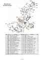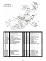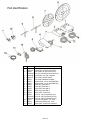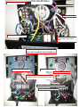
1
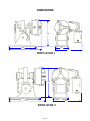
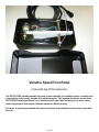
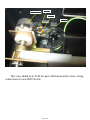
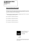
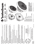
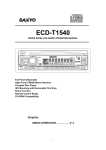
ROTO-STAR
BENCHTOP WELDING POSITIONER
USER’S MANUAL
JANCY ENGINEERING INC.
2735 Hickory Grove Road
Davenport, Iowa 52804
Phone (563) 391-1300
Fax (563) 391-2323
Jancy Bench-Top Welding Positioner
Congratulations on your purchase of a Jancy welding positioner. Please take a moment to complete
and mail your product warranty registration card. Doing so will validate your machine’s warranty period
and ensure prompt service if needed. Thank you for selecting a welding positioner from
Jancy Engineering Inc.
TABLE OF CONTENTS
Table of contents and warranty………………………………………………………... 2
Important safety and special instructions……………………………………………… 3
Installation and package contents……………………………………………………... 4
Maintenance and parts not shown...…………………………………………………… 5
Optional equipment and specifications………………………………………………… 6-7
Breakdown and parts list ROTO-STAR 1…………………………………………….. 8
Breakdown and parts list ROTO-STAR 3…………………………………………...... 9
Part identification……………………………………………………………………….… 10-11
Variable speed pedal reference view………………………………………………...... 12
Clarification view for RO538……………………………………………………………..13
Purge plug………………………………………………………………………………… 14
LIMITED WARRANTY
Jancy Engineering Inc. will, within (12) months from the original date of purchase, repair or replace any goods
found to be defective in materials or workmanship, provided the product warranty registration card has
been returned to Jancy Engineering Inc. within (30) days of purchase date. This warranty is void if the item
has been damaged by accident, neglect, improper service or other causes not arising out of defects in
materials or workmanship. This warranty does not apply to machines and/or components that have been
altered, changed, or modified in any way, or subject to use beyond recommended capacities and specifications. Electrical components are subject to respective manufactures warranties. All goods returned defective
shall be returned prepaid freight to Jancy, which shall be the buyer’s sole and exclusive remedy for defective
goods. In no event shall Jancy Engineering be liable for loss or damage resulting directly or indirectly from
the use of merchandise or from any other cause. Jancy Engineering is not liable for any costs incurred on
such goods or consequential damages. No officer, employee or agent of Jancy is authorized to make oral
representations of fitness or to waive any of the foregoing terms of sale and none shall be binding on Jancy.
JANCY ENGINEERING RESERVES THE RIGHT TO MAKE
IMPROVEMENTS AND MODIFICATIONS TO DESIGN WITHOUT PRIOR NOTICE
2 of 14
IMPORTANT SAFETY INSTRUCTIONS
WARNING!
WHEN USING ELECTRIC TOOLS, BASIC SAFETY PRECAUTIONS SHOULD ALWAYS BE FOLLOWED
TO REDUCE RISK OF FIRE, ELECTRIC SHOCK AND PERSONAL INJURY.
READ AND SAVE ALL INSTRUCTIONS FOR FUTURE REFERENCE
1.
Keep work area clean
Cluttered areas and benches invite injuries.
2.
Consider work area environment
Do not expose power tools to rain.
Do not use power tools in damp or wet locations.
Keep work area well lit.
Do not use tool in presence of flammable liquids or gases.
3.
Guard against electric shock
Prevent body contact with grounded surfaces. For example: pipes, radiators, ranges and refrigerator enclosures.
4.
Keep children away
Do not let visitors contact tool or extension cord.
All visitors should be kept away from work area.
5.
Store idle tools
When not in use, tools should be stored in a dry, high and locked-up place, out of reach of children.
6.
Do not force tool
It will do the job better and safer at the rate for which it was intended.
7.
Use the right tool
Do not force a small tool or attachment to do the job of a heavy-duty tool.
8.
Dress properly
Do not wear loose clothing or jewelry. They can be caught up in moving parts.
Non-skid foot wear is recommended when working outdoors.
Wear protective hair covering to contain long hair.
9.
Check for damaged parts
Before further use of the tool, a guard or other part that is damaged should be carefully checked to determine that
it will operate properly and perform its intended function. Check for alignment of moving parts, binding of moving
parts, breakage of parts, mounting and any other condition that may effect its operation. A guard or other part that
is damaged should be properly repaired or replaced by an authorized service center. Do not use this tool if
switches do not turn it on and off. Have defective switches replaced by an authorized service center.
1.
Always securely fasten the ROTO-STAR to the work surface, using ½” bolts through the holes in the base plate.
The ROTO-STAR is not stable unless fastened down, especially with a load in the chuck or on the face plate.
2.
Use caution when changing the tilt position of the ROTO-STAR. Never remove the tilt bolt unless the tilting
portion of the ROTO-STAR is securely held. Never attempt to change the tilt position with a load in the chuck or
on the face plate.
3.
Ensure that the ROTO-STAR is securely attached to the welder’s ground lead, either through the underside of the
base plate to a grounded metallic work surface, or by clamping the welder’s ground lead to the ground stud on the
base plate.
4.
Never reverse the direction of rotation with the motor running. Allow the motor to come to a complete stop before
reversing. Failure to do so will result in excessively high motor current, possibly resulting in damage to the motor
and or controller.
WARNING: SPECIAL INSTRUCTIONS
3 of 14
INSTALLATION
WARNING
Read and follow all instructions
1.
Securely bolt or clamp the ROTO-STAR to the work surface.
It is imperative that the base plate of the ROTO-STAR be securely fastened to a stable work surface. Failure to do
so may result in the ROTO-STAR and its load tipping over, possibly resulting in equipment damage and or
operator injury. Use ½ “bolts through the mounting holes provided in the base plate. If so desired, the grounding
of the ROTO-STAR may be accomplished by securing the unit to a metallic work surface that is connected to the
welding machine ground (the under side of the ROTO-STAR is bare metal).
2.
Attach ROTO-STAR to welding machine ground.
If you have bolted the ROTO-STAR to a metallic work surface in step 1 above, then ensure that the welding
machine ground is securely attached to the work surface. If it is not possible to ground the ROTO-STAR through
the work surface, then attach the welding machine ground clamp to the aluminum ground stud located on the
base plate below the chuck. Failure to securely ground the ROTO-STAR to the welding machine will result in
motor and or controller damage. The ROTO-STAR warranty does not cover damage due to failure to
properly ground the unit.
3.
Attach ROTO-STAR motor to controller.
Plug the ROTO-STAR motor into the controller. Rotate the cable connector against the socket on the controller
until it drops into place, and then rotate the outer ring on the cable connector to lock it in place.
4.
Attach motor controller to foot pedal and AC line.
Plug the motor controller AC line into the connector on the end of the foot pedal cord. Then plug the foot pedal
connector into the AC line socket. The foot pedal acts as a switch in the AC line, applying power to the motor
controller only when depressed.
5.
Test ROTO-STAR motion.
Test the installation as follows:
A) Turn the speed control knob on the motor controller fully CCW (zero RPM).
B) Turn the AC power switch on the motor controller ON (may be marked 0/1, 1 is on).
C) If so equipped, switch the Break/Run switch on the controller to Run.
D) Depress the foot pedal. Slowly turn the speed control knob CW to start rotation.
You should be able to go from Zero RPM at fully CCW on the speed control to maximum speed (approx 15
RPM on the ROTO 1 and 8 on the ROTO 3) at fill CW. Lifting off the foot pedal should stop all rotation. With
the motor stopped, change the direction of rotation by switching the FWD/REV switch on the controller, and
again press the foot pedal and check rotation in the opposite direction.
NEVER CHANGE ROTATION DIRECTION WITH THE MOTOR RUNNING.
Doing so will cause excessive motor current, possibly resulting in damage to the motor and or controller.
Package contents
ROTO-STAR 1 and 3
Main unit with chuck
T-handle
5/16” Allen (type) wrench
Warranty card
DVD
Manual
Foot pedal
Control box
ROTO-STAR 1-P and 3P
Main unit with face plate
Warranty card
DVD
Manual
Foot pedal
Control box
4 of 14
MAINTENANCE
PERIODICALLY CHECK THE FOLLOWING MAINTENANCE ITEMS TO
ENSURE CONTINUED TROUBLE FREE OPERATION OF YOUR ROTO-STAR:
1.
Add a few drops of lubricating oil to the two oil fittings on the spindle housing.
2.
Check that all connections to the welder ground system are secure and clean.
3.
Check the drive chain for proper tension. If the chain is too loose, the spindle may reverse direction slightly when
the motor is stopped, especially if the load is not balanced. Tighten the chain as follows:
A) Loosen the two set screws securing the motor mount pins located on the back side of the spindle housing.
B) Loosen the two 10-32 screws on the side of the chain guard where it attaches to the angle bracket to the motor
mount. Do not loosen the screws attaching the guard bracket to the motor mount.
C) On the ROTO-STAR 1, loosen the two 5/16 nuts attaching the chain guard to the front of the spindle housing.
The studs these nuts are on are actually long set screws that secure the motor mount pins on the front side of
the spindle housing. Loosen these two set screws with an Allen type wrench to allow the motor mount pins to
move in the housing.
On the ROTO-STAR 3, remove the two 5/16 bolts securing the chain guard to at the front of the spindle
housing. Then, using an Allen type wrench, loosen the two set screws securing the motor mount pins.
D) You should now be able to slide the motor assembly back, tightening the drive chain. It will be necessary to
apply pressure to the motor assembly, holding the chain tight, while you tighten a set screw on each motor
mount pin. The slotted attachment for the chain guard should allow sufficient movement of the motor assembly
to allow the chain guard to be tightened. If not, the chain may need replacement.
E) Reverse the steps above to tighten the four set screws securing the motor mount pins, the guard screws to the
angle bracket, and the guard attachment at the front of the spindle housing.
Parts not shown
Part#
RO631-DGR130
RO633-2
RO635
RO637
RO639
RO641
RO647
RO721
Description
Kit, low gearing for Roto-Star 3
Motor, Roto-Star 3 (220 V)
Motor brush, Roto-Star 1
Motor brush, Roto-Star 3
Brush cover, Roto-Star 1
Brush cover, Roto-Star 3
Kit, low gearing for Roto-Star 1
Hex key, 5/16 inch (short)
5 of 14
RO507 - 16" diameter for 3-P
RO503 - 12" diameter for 1-P
RO574 - Wing Bolt, adjustable clamp
ROTO-STAR 3-P (shown)
ROTO-STAR 1-P (not shown)
6 of 14
DIMENSIONS
11.6
12.0
6.0
14.4
11.7
ROTO-STAR 1
14.4
15.0
17.5
7.5
13.5
ROTO-STAR 3
7 of 14
Breakdown
ROTO-STAR 1
Item
1
2
3
4
5
6
7
8
9
10
11
12
13
14
15
16
17
18
19
20
21
22
Part
RO653
RO655
RO621
RO659
RO665
RO667B
RO667A
RO670
RO671
RO673
RO676
RO677
RO631
RO682
RO685
RO686
RO687
RO689
RO565
RO690
RO692
RO694
Description
Base Frame Assy., Roto-Star 1
Upper Frame, Roto-Star 1
Chuck, 3 jaw Roto-Star 1
Drive Shaft Weldment, Roto-Star 1
Spacer Ring, Roto-Star 1
Thrust Washer Plate, Roto-Star 1
Thrust Washer Bearing, Roto-Star 1
Bronze Bushing
Rear Locking Collar, Roto-Star 1
Chain Tension Rod, Roto-Star 1
Gear, 45T Roto-Star 1
Motor Mount Plate, Roto-Star 1
Motor, 90 VDC - Roto-Star 1
Pinion Gear, 10T Roto-Star 1
Chain, Roto-Star 1
Chain Guard, Roto-Star 1
Chain Guard, bracket #1 Roto-Star 1
Chain Guard, bracket #2
Grounding Contact, 12" long
Grounding Post
Handle with Knob, Roto-Star 1
Scr, HHCS 1/2"-13 x 5 1/2
Qty. Item
Part
1
23 RO693
1
24 RO697
1
25 RO696
1
26 RO698
1
27 RO706
2
28 RO714
1
29 RO701
2
30 RO719
1
31 RO708
2
32 RO716
1
33 RO702
1
34 RO645
1
35 RO710
1
36 RO700
1
37 RO718
1
38 RO713
1
39 RO704
1
40 RO699
1
41 RO707
1
42 RO705
1
43 RO576
1
8 of 14
Description
Knob
Washer, flat 1/2" SS
Nut, 1/2"-13 nylock
Washer, flat 1/2" ss (large od)
Scr, FHSCS 3/8"-16 x 3/4 ss
Scr, SHCS M8-1.25 x 20 ss
Washer, flat 5/16" ss
Scr, CPSSS 5/16"-18 x 3/8 ss
Scr, HHCS 1/2"-13 x 1 1/4 ss
Scr, SHCS 3/8"-16 x 3/4 ss
Washer, flat 3/8" ss
Scr, SHCS 1/4"-20 x 3/4 ss
Scr, SHCS 1/4"-20 x 1/2 ss
Washer, flat 1/4" ss
Scr, CPSSS 1/4"-20 x 1/4 ss
Scr, SHCS 5/16"-18 x 5/8 ss
Scr, BHCS 10-32 x 3/8 ss
Washer, flat #10 ss
Scr, HHCS 10-32 x 1/2 ss
Scr, BHCS 10-32 x 1/2 ss
Motor cord (only) with plug
Qty.
1
4
1
2
2
3
5
10
1
1
1
4
1
5
1
2
3
5
1
1
Breakdown
ROTO-STAR 3
Item
1
2
3
4
5
6
7
8
9
10
11
12
13
14
15
16
17
18
19
20
21
22
23
24
25
Part
RO578
RO657
RO623
RO661
RO669
RO663
RO668B
RO668A
RO651
RO672
RO674
RO675
RO679
RO633
RO681
RO683
RO684
RO509
RO688
RO689
RO566
RO567
RO690
RO691
RO693
Description
Base Frame Assy., Roto-Star 3
Upper Frame, Roto-Star 3
Chuck, 3 jaw Roto-Star 3
Drive Shaft Weldment, Roto-Star 3
Contact Plate
Spacer Ring, Roto-Star 3
Thrust Washer Plate, Roto-Star 3
Thrust Washer Bearing, Roto-Star 3
Bronze Bushing
Rear Locking Collar, Roto-Star 3
Chain Tension Rod, Roto-Star 3
Gear, 45T Roto-Star 3
Motor Mount Plate, Roto-Star 3
Motor, 90 VDC - Roto-Star 3
Pinion Gear, 10T Roto-Star 3
Key, 3/16" x 1"
Chain, Roto-Star 3
Chain Guard, Roto-Star 3
Chain Guard, bracket #1 Roto-Star 3
Chain Guard, bracket #2
Grounding Contact, 13" long
Ground Strap
Grounding Post
Handle with Knob, Roto-Star 3
Knob
Qty.
1
1
1
1
1
1
2
1
2
1
2
1
1
1
1
1
1
1
1
1
1
1
1
1
1
9 of 14
Item
26
27
28
29
30
31
32
33
34
35
36
37
38
39
40
41
42
43
44
45
46
47
48
49
50
Part
Description
RO711 Scr, HHCS 1/2"-13 x 7
RO697 Washer, flat 1/2" ss
RO698 Washer, flat 1/2" ss (large od)
RO696 Nut, 1/2"-13 nylock
RO706 Scr, FHSCS 3/8"-16 x 3/4 ss
RO710 Scr, SHCS 1/4"-20 x 1/2 ss
RO700 Washer, flat 1/4" ss
RO709 Scr, BHCS 1/4"-20 x 1 ss
RO695 Nut, 1/4"-20 ss
RO717 Scr, SHCS M10 X 1 ss
RO702 Washer, flat 3/8" ss
RO720 Scr, CPSSS 5/16"-18 x 1/2 ss
0010185 Scr, CPSSS 3/8"-24 x 5/16
RO718 Scr, CPSSS 1/4"-20 x 1/4 ss
RO719 Scr, CPSSS 5/16"-18 x 3/8 ss
RO708 Scr, HHCS 1/2"-13 x 1 1/4 ss
RO715 Scr, SHCS 5/16"-18 x 3/8 ss
RO701 Washer, flat 5/16" ss
RO697 Washer, flat 1/2" ss
RO712 Scr, SHCS 1/4"-20 x 1 ss
RO707 Scr, HHCS 10-32 x 1/2 ss
RO705 Scr, BHCS 10-32 x 1/2 ss
RO704 Scr, BHCS 10-32 x 3/8 ss
RO699 Washer, flat #10 ss
RO576 Motor cord (only) with plug
Qty.
1
4
2
1
1
1
6
1
1
3
3
2
2
2
6
3
2
2
2
4
1
1
4
6
Part identification
Item
Part
1 RO515
RO515-2
2 RO540
RO540-15
3 RO540-B
4 RO540-F
5 RO520
6 RO505
7 RO501
8 RO525
9 RO530
10 RO555
11 RO550
12 RO536
13 RO538
RO538-15
RO538-50
14 RO537
15 RO526
16 RO539
Description
Control Box, complete (std.)
Control Box, complete (std.)-220v
Foot Pedal, var. spd. w/cont. box
Foot Ped.,var.spd.w/con.box/w15'crd.
Control Box, var. spd. complete
Foot Pedal, variable speed
Foot Pedal, standard complete
Surface Plate, 16" for chuck(ROTO3)
Surface Plate, 12" for chuck(ROTO1)
Chuck Key, Roto-Star 3
Chuck Key, Roto-Star 1
Purge Plug, Roto-Star 3
Purge Plug, Roto-Star 1
Power Cord, control box
Cord, var. spd. foot pedal 8' long
Cord, var. spd. foot pedal 15' long
Cord, var. spd. foot pedal 50' long
Cord, std. foot pedal - 7' 6" long
Female Plug Socket, ext. cord
Power Cord, control box extension
10 of 14
Part identification
Bottom view of switch plate.
RO643 - POTENTIOMETER
RO615 - 15 A - fuse
RO513 - PC Board, control box
Some of the older control boxes
had 20 A fuses - part number
RO620
Reference views of control box's with
some part numbers and descriptions.
RO540-B - with top cover off
Top view of switch plate
RO515 - with top cover off
RO649 - Ceramic Capacitor, 10000PF 250V
Note: Some boxes may not have this capacitor
RO517 - PC Board, variable speed foot pedal
RO544 - Motor cord, receptacle
11 of 14
Variable Speed Foot Pedal
(View with top off for reference)
The ROTO-STAR variable speed foot pedal system consists of a modified motor controller and
a heavy duty continuously variable foot pedal assembly. This system allows the speed of the
ROTO-STAR welding positioner to be controlled with your foot, allowing you to more easily
weld complex parts that require different speeds on different areas.
For those of you that purchased this option the safety and installation instructions came with
the unit.
12 of 14
RO540-F-1
WIRE# 2
WIRE# 1
WIRE# 3
This view added on 4-25-08 for part clarification and to show wiring
connections for new RO538 cord.
13 of 14
PURGE PLUG
When welding certain metals, like stainless steel, inconel, titanium, etc, the back side of the weld will end up
covered in “black sugar” (as welders call it) if not kept in an inert gas (such as argon) atmosphere.
This is usually an issue when welding pipe or tubing made of these materials.
The purge plug attaches to the back end of the ROTO-STAR spindle, and allows purge gas to be flooded into the
interior of the spindle and then into the interior of the pipe being welded.
When done this way, the interior of the weld will look as good or better than the outside, and the weld will infact be
stronger (this isn’t just cosmetic).
Most high-purity piping or aircraft work REQUIRES that purge gas be used.
JUNE - 2009
14 of 14