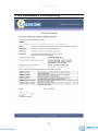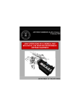
1
ATEX & Class1 Division1
User Instructions
iCAM501U
This device complies with part 15 of the
FCC Rules. Operation is subject to the
following two conditions: (1) This device
may not cause harmful interference, and
(2) this device must accept any
interference received, including
interference that may cause undesired
operation
Country of Origin: United Kingdom
www.atex-shop.de
Operating Manual
This page is intentionally left blank.
2
www.atex-shop.de
Operating Manual
Document Number 332346
Revision 02 (based on safety instructions 331684_02)
©2011 Extronics Limited. This document is Copyright Extronics limited.
Extronics reserve the right to change this manual and its contents without notice, the latest
version applies.
3
www.atex-shop.de
Operating Manual
Contents
Contents ..................................................................................................................... 4
1 Safety Information and Notes .............................................................................. 5
1.1
Storage of this Manual ................................................................................. 5
1.2
List of Notes ................................................................................................. 5
2 User Guide .......................................................................................................... 7
2.1
Changing/Installing Batteries........................................................................ 7
2.2
Preparing for first use ................................................................................... 9
2.3
Powering On / Off........................................................................................10
2.4
Setting Time and Date of the iCAM501U ....................................................10
2.5
Taking a picture...........................................................................................11
2.5.1
Taking a picture....................................................................................12
2.5.2
Enabling the Flash ...............................................................................13
2.5.3
Enabling the Audio Recording Feature ................................................14
2.5.4
Image blur analysis feature ..................................................................15
2.5.5
Variable flash brightness......................................................................16
2.5.6
Picture Time Stamping.........................................................................16
2.5.7
Error Codes..........................................................................................16
2.6
Installing the iCAM501U With an Operating System ...................................17
2.6.1
Windows XP.........................................................................................17
2.6.2
Windows Vista / Windows 7 .................................................................18
2.7
Setting Time and Date of the iCAM501U ....................................................20
2.7.1
Setting Time and Date in Windows XP ................................................20
2.7.2
Setting Time and Date in Windows Vista .............................................21
2.7.3
Setting Time and Date in Windows 7 ...................................................21
2.7.4
Setting Time and Date in Apple OSX ...................................................22
2.8
Configuring How the Camera Behaves With Windows XP..........................23
2.9
Configuring How the Camera Behaves With Windows Vista/Windows 7 ....24
2.10 Configuring How the Camera Behaves With Apple OSx .............................25
2.11 Compatibility of the iCAM501U LED flash with optical flame detection
equipment ..............................................................................................................28
3 Structure and Function .......................................................................................29
3.1
Intended Purpose Usage.............................................................................29
3.2
Transportation and Storage.........................................................................29
3.3
Authorized Persons .....................................................................................29
3.4
Cleaning and Maintenance..........................................................................29
3.5
Safety Precautions ......................................................................................30
3.6
Cleaning and Maintenance Intervals ...........................................................30
3.7
Aggressive substances and environments ..................................................30
3.8
Exposure to external stresses .....................................................................30
4 Technical Data ...................................................................................................31
5 EC Declaration of Conformity .............................................................................32
6 FM Class 1 Division 1 USA Certificate of Compliance........................................33
7 FM Class 1 Division 1 Canadian Certificate of Compliance................................35
8 Revision History .................................................................................................37
4
www.atex-shop.de
Operating Manual
1 Safety Information and Notes
1.1
Storage of this Manual
Keep this user manual safe and in the vicinity of the device. All persons required to work with the
device should be advised on where this manual is stored.
1.2
List of Notes
The notes supplied in this chapter provide information on the following.
•
Danger! / Warning!
o
•
Caution
o
•
Possible damage to property.
Important
o
•
Possible hazard to life or health.
Possible damage to enclosure, device or associated equipment.
Information
o
Notes on the optimum use of the device
Warning!
For ATEX applications, ONLY Duracell Plus MN1500 or Duracell Procell
MN1500 cells may be used with the iCAM501U.
Warning!
Any connection to the iCAM501 USB port must NOT be made in a
hazardous area.
Warning!
For Class1 Division 1 applications NOTE THE REDUCED TEMPERATURE
CLASSSIFICATION of T4 at 55oC when Duracell MN1500/ Duracell Procell
MN1500 cells are used.
Warning!
For Class 1 Division 1 applications ONLY, Duracell Procell PC1500 or
Energizer E91 cells may additionally be used, NOTE THE REDUCED
TEMPERATURE CLASSIFICATION of T3C at 50oC ambient when these
cells are used (see Table 1).
Warning!
The user shall NOT mix MN1500, PC1500 or E91 cells in ANY application
Warning!
For GROUP I applications ONLY, the changing of the cells in the
hazardous area or the transportation of spare cells into the hazardous
area is NOT PERMITTED.
5
www.atex-shop.de
Operating Manual
Warning!
For GROUP II applications ONLY, the user shall not carry more than a
maximum of 2 spare Duracell Plus MN1500 or Duracell Procell MN1500
cells into the hazardous area. Precautions shall be taken to prevent
short circuiting of un-protected cell terminals. Discharged cells shall be
removed from the hazardous area.
Warning!
For Class 1 Division 1 applications ONLY, the user shall not carry more
than a maximum of 2 spare Duracell Plus MN1500, Duracell Procell
MN1500/PC1500 or Energizer E91 cells into the hazardous area.
Precautions shall be taken to prevent short circuiting of un-protected
cell terminals. Discharged cells shall be removed from the hazardous
area.
Warning!
For GROUP II applications ONLY the rated ambient temperature range of
the equipment is from -20oC to 60oC.
Warning!
For GROUP I applications ONLY the rated ambient temperature range of
the equipment is from 0oC to 60oC.
Warning!
For Class 1 Division 1 applications ONLY the rated ambient temperature
range of the equipment is from -20oC to 50 oC/55oC dependent on which
cells are used (see Table 1).
Warning!
If any damage to the iCAM501U is found which may invalidate the
required safety minimum IP rating (IP54 for group I applications), (IP20
for group II and class 1 division 1 applications), the iCAM501U shall be
removed from the hazardous area.
Important
Any repairs or replacement of parts MUST be performed by the
manufacturer or its nominated sub contractor or agent.
Important
The iCAM501U contains no user serviceable parts. The main part of the
enclosure must not be opened under any circumstances.
Application
Duracell Plus
MN1500
Duracell
Procell
MN1500
Duracell
Procell
PC1500
ATEX GROUP
II
ATEX GROUP
I
CLASS 1
DIVISION 1
OK, T4 at 60oC OK, T4 at 60oC CANNOT BE
USED
o
o
OK, T4 at 60 C OK, T4 at 60 C CANNOT BE
USED
OK, T4 at 55oC OK, T4 at 55oC OK, T3C at
50oC
Table 1 iCAM501U cell usage table
6
www.atex-shop.de
Energizer E91
CANNOT BE
USED
CANNOT BE
USED
OK, T3C at
50oC
Operating Manual
2 User Guide
2.1
Changing/Installing Batteries
To change or install the batteries in the iCAM501U turn the screw as indicated below
to remove the cover
Warning!
For ATEX applications, ONLY Duracell Plus MN1500 or Duracell Procell
MN1500 cells may be used with the iCAM501U.
Warning!
For Class1 Division 1 applications NOTE THE REDUCED TEMPERATURE
CLASSSIFICATION of T4 at 55oC when Duracell MN1500/ Duracell Procell
MN1500 cells are used.
Warning!
For Class 1 Division 1 applications ONLY, Duracell Procell PC1500 or
Energizer E91 cells may additionally be used, NOTE THE REDUCED
TEMPERATURE CLASSIFICATION of T3C at 50oC ambient when these
cells are used (see Table 1).
Warning!
The user shall NOT mix MN1500, PC1500 or E91 cells in ANY application
Warning!
For GROUP I applications ONLY, the changing of the cells in the
hazardous area or the transportation of spare cells into the hazardous
area is NOT PERMITTED.
Warning!
For GROUP II applications ONLY, the user shall not carry more than a
maximum of 2 spare Duracell Plus MN1500 or Duracell Procell MN1500
cells into the hazardous area. Precautions shall be taken to prevent
short circuiting of un-protected cell terminals. Discharged cells shall be
removed from the hazardous area.
7
www.atex-shop.de
Operating Manual
Use a coin to turn the screw
anti-clockwise, the lid should
then pop up.
To close it again, turn the
coin clockwise, the screw
should click into place once
correctly seated.
Install the batteries in the correct orientation (indicated on the enclosure) and close
the lid again.
8
www.atex-shop.de
Operating Manual
2.2
Preparing for first use
The iCAM501U is shipped with a protective film fitted to the front and rear windows.
This should be carefully removed before use.
The iCAM501U may be used with the protective rubber overboot supplied. This fits
over the camera and provides additional impact resistance. Only the rubber overboot
supplied by Extronics should be used as it is made from electrostatically-dissipative
material.
9
www.atex-shop.de
Operating Manual
2.3
Powering On / Off
Information The iCAM501U must be fully powered on before plugging a USB cable
into the camera or to take a picture. This will be indicated when the
green LED has stopped flashing.
Green LED will flash rapidly for ~10
seconds while the camera boots.
The Blue and Red LED will flash
briefly during boot up. The Green
LED then goes solid when ready for
operation. If the green LED flashes
slowly after booting, this indicates a
low battery level.
Press and hold the “FLASH”
and “RECORD” buttons
simultaneously until the “ON”
LED starts to flash green.
The diagrams above show how to power on the iCAM501U. The same procedure is
required to turn the iCAM501U off. Once it is turned off no LED’s should be lit.
2.4
Setting Time and Date of the iCAM501U
The iCAM501U has an internal clock which is used to time code the JPEG file with
information on when a picture and audio file was taken. The internal clock will have
been set to GMT when the camera was manufactured. However, if it has been stored
for a significant time without batteries, the internal clock may need to be set when the
camera is first used.. The time and date must be set using a PC via the USB
interface.
10
www.atex-shop.de
Operating Manual
2.5
Taking a picture
There are a few different options available when taking a picture:
•
A picture can be taken with no flash and no audio recording
•
A picture can be taken with a flash to allow a good picture to be taken in low
light conditions.
•
A picture can be taken and an audio recording taken after the picture has
been taken to provide an audio record for the picture.
•
Or a picture can be taken with a flash and also create an audio recording.
Once a picture has been taken the LEDs and the buzzer are used to indicate if a
good picture has been taken or not. For more details, the latest full iCAM501U
manual can be found on the Extronics website at www.extronics.com
11
www.atex-shop.de
Operating Manual
2.5.1 Taking a picture
Green LED will flash
rapidly when picture is
being taken. Ensure
you keep your hand
still. See page 10/11
for details of LED
status codes
Press and hold trigger button
until green LED starts
flashing rapidly, wait for
green LED to stop flashing
before moving
12
www.atex-shop.de
Operating Manual
2.5.2 Enabling the Flash
Once the flash button is pressed
the red LED will start to flash,
after some seconds the LED will
become solid indicating the flash
has charged and is ready for use.
The green LED may also flash
slowly if the battery level is low
Press the “FLASH”
button to enable the flash
feature of the camera.
To take a picture move your eye to the view finder and position the camera so that
you can see what it is you would like to take a picture of, the point of interest should
be at least 30cm from the lens. The reticule can be used to frame the image you
want to capture. Note that the actual picture is about 15% larger either side of the
actual viewfinder image.
Press and hold the large button (indicated as the “Picture Taking Button” above). The
green ‘ON’ LED will then flash to indicate the picture taking process is active. Keep
the camera as still as possible until the green LED has stopped flashing. Once the
camera has taken a picture the 3 LEDs will flash in a sequence to let you know
whether the picture taken was of a good quality (Table 2) or poor quality (Table 3).
Once this occurs you can release the button unless you wish to create a voice
recording (see below for more details). Note that if you are not making a voice
recording it is possible to just press the picture taking button momentarily if preferred.
13
www.atex-shop.de
Operating Manual
2.5.3 Enabling the Audio Recording Feature
Once the recording feature is
enabled the blue LED will
turn on indicating it is ready
for use.
Press the “RECORD” button
to enable the recording feature
of the camera.
Press and HOLD trigger button,
WAIT until blue LED begins to
flash, then record audio and
release trigger button when
finished
14
www.atex-shop.de
Operating Manual
Sequence
LED 1
LED 2
LED 3
1
2
Off
Off
Off
3
4
Off
Off
Off
5
6
Off
Off
Off
Table 2 LED indication of good image
Sequence LED 1
LED 2
LED 3
1
Off
Off
2
Off
Off
3
Off
Off
4
Off
Off
5
Off
Off
6
Off
Off
7
Off
Off
8
Off
Off
9
Off
Off
Table 3 LED indication of poor image
The iCAM501U will still store the picture even if it is flagged up as being of poor
quality. The reason for this is that factors such as the lighting conditions may mean it
is not possible to get a perfect picture and a poor one is better than no picture.
However it is strongly recommended that another picture is taken.
If the flash is required when taking a picture in low lighting conditions, turn the flash
on as indicated in the above section and wait until the red LED stays constantly on.
Note the flash can take up to 20 seconds to fully charge when the batteries are part
used. Once the red LED has turned solid the iCAM501U is then ready to take a
picture in the same way as if the flash was not enabled (the flash will automatically
trigger when the picture is being taken).
2.5.4 Image blur analysis feature
The iCAM501U firmware has an additional image blur analysis feature. Images are
analysed for characteristics of blurring, and given a score, which is in turn compared
with a threshold based on the average light level in the image. Good or bad images
are indicated using the LED sequence previously described in Table 2 and Table 3.
However, the reliability of the image analysis function is dependent on the nature of
the scene being photographed. Images which contain little or no details such as
edges (for example a blank wall) may be indicated as blurred when they are in-fact
acceptable. Therefore the user should bear this limitation in mind when taking
pictures, and it is suggested that users should take some practice shots to get a ‘feel’
for the way in which this software behaves.
Note that the iCAM501U also has an anti-shake function. It takes four pictures and
then selects the best quality one to save to the flash memory. This is the reason that
the flash fires 4 times. This operates independently of the image blur analysis
feature, which examines the best of the 4 images taken.
15
www.atex-shop.de
Operating Manual
2.5.5 Variable flash brightness
The iCAM501U firmware has an additional variable flash brightness feature. The
purpose of this feature is to reduce the incidence of over-exposure of images when
close-up shots of reflective surfaces are taken with the flash.
When the flash is enabled, and a shot is triggered, a short low-brightness ‘ranging’
flash pulse will firstly be seen. Immediately followed by the four flash pulses
previously described, or a single continuous ‘torch’. The iCAM501U software rapidly
analyses the reflected light level from the ranging pulse, and adjusts the brightness of
the flash accordingly. However, this system is not infallible, and so the flash may still
be too bright under some circumstances. The camera will indicate a bad image if the
light level is extremely high, but if you are trying to photograph text close-up on a
reflective rating plate for example, it is strongly recommended to use ambient lighting
where possible in such applications.
2.5.6 Picture Time Stamping
The iCAM501U has an additional feature which will ‘time stamp’ the pictures as they
are taken. Once a picture is taken the iCAM501U will stamp the current time and
date in an area on the bottom-left of the picture to allow photographs to be easily
identifiable.
It should be noted that once a good/bad image has been indicated, there will be a 2
second delay before an audio recording can begin or another shot can be triggered.
2.5.7 Error Codes
•
If the green LED continually flashes slowly once booted, this means that the
batteries are running low and will soon need replacing.
•
If the iCAM501U has all 3 LEDs constantly flashing it means that it is in an
unrecoverable state. The only way to get it out of this state is to remove the
batteries and then replace them.
16
www.atex-shop.de
Operating Manual
2.6
Installing the iCAM501U With an Operating System
This section will provide details on how to install the iCAM501U to be used with a
supported host operating system. Although the iCAM501U supports various Linux
versions with the PTP library installed and Mac OsX 10.x this manual only focuses on
Windows operating systems. The iCAM501U is PTP compliant so should work in the
same way as many other digital cameras do with various operating systems
The iCAM501U must be powered on and the green status LED must be solid before
connecting to a host operating system, otherwise the operating system will not
establish communication with the camera. Once the green LED has become solid
connect the ICAM501U via a USB cable to the host computer.
2.6.1 Windows XP
Once the iCAM501U has been connected to a machine running Windows XP, the
drivers and software required to establish communication between them will
automatically be installed. A “balloon” icon will show up in the taskbar stating that
“Your new hardware is installed and ready to use”.
If the Windows Autorun feature is enabled (it is enabled by default) a window like the
one below will be shown. By clicking on any of the listed programs and then clicking
ok the files currently on the camera will be displayed in the chosen application. By
clicking cancel nothing will open.
17
www.atex-shop.de
Operating Manual
Information on customizing the way the iCAM501U interacts with Windows XP can
be found in section 2.8
2.6.2 Windows Vista / Windows 7
Once the iCAM501U has been connected to a machine running Windows Vista or
Windows 7, the drivers and software required to establish communication between
them will automatically be installed. A “balloon” icon will show up like the one pictured
below
If the Windows Autoplay feature is enabled (it is enabled by default) a window like the
one below will be shown. By clicking on any of the listed options and then clicking ok
the files currently on the camera will be displayed in the chosen application. By
clicking the close button nothing will happen.
18
www.atex-shop.de
Operating Manual
Information on customizing the way the iCAM501U interacts with Windows
Vista/Windows 7 can be found in section 2.9
19
www.atex-shop.de
Operating Manual
2.7
Setting Time and Date of the iCAM501U
The iCAM501U has an internal clock which is used to time code the JPEG file with
information on when a picture and audio file was taken. The internal clock will need
to be set when the camera is first used or when the batteries have been flat for an
extended period of time. If the time and date is not set the JPEG files will have an
incorrect time code embedded into the file.
2.7.1 Setting Time and Date in Windows XP
Attach the iCAM501U to the machine running Windows XP once the green status
LED has turned solid. Navigate to my computer where an icon for the iCAM501U will
be displayed as shown below. Right click on the iCAM501U icon and click properties.
When the camera is first plugged in click properties and the following display is likely
to be shown.
20
www.atex-shop.de
Operating Manual
If there are large numbers of pictures on the iCAM501U this may take some minutes
as it will download thumbnails for the pictures when it is first plugged in. If it is taking
an excessive amount of time try unplugging the USB cable and then reconnecting the
device.
Now to set the time, simply click the set time button, it will then synchronize with the
current Windows system time, you must therefore ensure that the Windows system
time is also set correctly.
2.7.2 Setting Time and Date in Windows Vista
It is currently not possible to set the time and date of the iCAM501U using Windows
Vista. This is due to Microsoft changing its PTP driver from thatthat used with
Windows XP. The driver does still allow files to be downloaded from the iCAM501U.
2.7.3 Setting Time and Date in Windows 7
As with Windows Vista the PTP driver written by Microsoft does not allow the time of
the camera to be set.
If you are running Windows 7 Professional, Enterprise or ultimate it is possible to set
the iCAM501U by downloading and using Windows XP mode. Please download
document 328303 from the iCAM501U page at www.extronics.com. This will detail
how to download, install and use Windows XP mode.
21
www.atex-shop.de
Operating Manual
2.7.4 Setting Time and Date in Apple OSX
PLEASE NOTE: THE iCAM501U is NOT COMPATIBLE WITH APPLE OSX BY
DEFAULT. CONTACT EXTRONICS FOR A SPECIAL OSX-COMPATIBLE
SOFTWARE RELEASE
To set the time and date using apples OSX navigate to finder->applications and open
image capture.
Click options…
Then click “set camera’s date and time”. Now when the iCAM501U is connected via
USB to the system, the time and date will automatically be synchronized.
22
www.atex-shop.de
Operating Manual
2.8
Configuring How the Camera Behaves With Windows XP
When the iCAM501U is first plugged into a Windows XP machine you will be
prompted to select an application to use to download the files from the Camera. This
default action can be changed using the same method as used for setting the time,
and then selecting the events tab.
23
www.atex-shop.de
Operating Manual
Choose from the following options:
Start this program: This allows you to tell Windows to automatically load a certain
application when the camera is plugged in. This list may vary depending on which
programs are installed. The default program should be “Microsoft Scanner and
Camera Wizard. This is the built in camera managing software included in Windows.
Prompt for which program to run: This will make Windows display a list of
programs which can manage the iCAM501U every time the iCAM501U is plugged
into a PC
Take no action: With this setting Windows will not prompt the user to take any
actions when the iCAM501U is plugged in.
Save all pictures to this folder: This setting will allow the user to set a directory
where all pictures and audio files are automatically downloaded to when the
iCAM501U is plugged into the PC. You also have the option to have all files
downloaded to a folder with today’s date and to delete the files from the camera once
downloaded.
2.9
Configuring How the Camera Behaves With Windows Vista/Windows 7
When the iCAM501U is first plugged into a Windows Vista or Windows 7 machine
you will be prompted to select an application to use to download the files from the
Camera. This default action can be changed in the AutoPlay popup menu as shown
below. It is possible to completely turn off the AutoPlay feature by selecting the “View
24
www.atex-shop.de
Operating Manual
more AutoPlay options in Control Panel”. From there you can disable the AutoPlay
feature for all devices or just the iCAM501U.
More information on downloading files can be found in section Error! Reference
source not found.
2.10 Configuring How the Camera Behaves With Apple OSx
When the iCAM501U is first plugged in iPhoto will automatically start. iPhoto
currently doesn’t allow the audio files on the camera to be downloaded, only the
pictures.
To change what the camera does when it is first plugged in close iPhoto, click finder>applications->image capture and click on preferences
25
www.atex-shop.de
Operating Manual
Click on ”When a camera is connected open:” and select image capture
Now when the iCAM501U is plugged in the following windows will open
Select what you wish to download from the drop down box, or select an automatic
task.
26
www.atex-shop.de
Operating Manual
Click on options…. to set further options for the iCAM501U.
27
www.atex-shop.de
Operating Manual
2.11 Compatibility of the iCAM501U LED flash with optical flame detection
equipment
The flash LEDs fitted to the iCAM501U operate with a peak wavelength of 440nm
(with a secondary lower peak at 550nm). Therefore the majority of the light emitted is
towards the blue end of the visible spectrum.
Typical UV/IR flame detectors operate in the 180-260nm UV range and the 20004000nm IR range. Consequently the majority of the energy emitted by the flash on
the iCAM501U is well outside of the operating range of typical flame detectors.
However, Extronics have not done any testing of the iCAM501U with optical flame
detectors, so we cannot guarantee compatibility with any specific model of detector.
If you do find that particular sensors may be activated by the flash, it can be turned
off by the user with the press of a key as per the operating instructions in 2.5.2. In
addition, if you require the flash to be completely disabled for a particular camera,
Extronics can send you a field-installable software version which will disable the flash
(this of course can be reversed as desired by re-installing the normal software
version, again in the field).
Figure 1 Flash LED output spectrum
28
www.atex-shop.de
Operating Manual
3 Structure and Function
3.1
Intended Purpose Usage
Important
Before setting the unit to work, read the technical documentation
carefully.
Important
The latest version of the technical documentation or the corresponding
technical supplements is valid in each case.
The iCAM501U is built using modern components and is extremely reliable in
operation; however it must only be used for its intended purpose. Please note that
the intended purpose also includes compliance with the instructions issued by the
manufacturer for installation, setting up and service.
Any other use is regarded as conflicting with the intended purpose. The manufacturer
is not liable for any subsequent damage resulting from such inadmissible use. The
user bears the sole risk in such cases.
3.2
Transportation and Storage
All iCAM501U devices must be so transported and stored that they are not subjected
to any excessive mechanical stresses.
3.3
Authorized Persons
Only persons trained for the purpose are authorized to handle the iCAM501U; they
must be familiar with the unit and must be aware of the regulation and provisions
required for explosion protection as well as the relevant accident prevention
regulations.
3.4
Cleaning and Maintenance
The iCAM501U and all its components require no maintenance. All work on the
iCAM501U by personnel who are not expressly qualified for such activities will cause
the Ex approval and the guarantee to become void.
29
www.atex-shop.de
Operating Manual
3.5
Safety Precautions
Important
3.6
For the installation, maintenance and cleaning of the units, it is
absolutely necessary to observe the applicable regulations and
provisions concerned with explosion protection (EN 60079-0, EN 6007914) as well as the Accident Prevention Regulations.
Cleaning and Maintenance Intervals
The cleaning intervals depend on the environment where the system is installed.
3.7
Aggressive substances and environments
The iCAM501U is not designed to come into contact with aggressive substances or
environments, please be aware that additional protection may be required.
3.8
Exposure to external stresses
The iCAM501U is not designed to be subjected to excessive stresses e.g. vibration,
heat, impact. Additional protection is required to protect against these external
stresses.
The iCAM501U will require additional protection if it is used in a location where it may
be subjected to damage.
The iCAM501U may be fitted with the optional antistatic rubber boot accessory
supplied by Extronics. However, this does not guarantee any additional impact
resistance, and due care must still be taken to avoid damage to the unit, and to
inspect it before taking into a hazardous area.
30
www.atex-shop.de
Operating Manual
4 Technical Data
Certification Number
ITS09ATEX26868X, IECEx ITS 09.0027X, FM 3042108/3042108C
ATEX Certification
II 1 G Ex ia IIB T4 Ga, II 2 G Ex ia IIC T4 Gb, -20°C ≤Ta≤ +60°C
I M1 Ex ia I Ma 0°C ≤Ta≤ +60°C
IECEx Certification
II 1 G Ex ia IIB T4 Ga, II 2 G Ex ia IIC T4 Gb, -20°C ≤Ta≤ +60°C
Ex ia I Ma 0°C ≤Ta≤ +60°C
FM Certification
Intrinsically Safe for Class 1, Division 1, Groups A,B,C,D T4/T3C -20°C≤Ta≤55/50°C
(USA and Canada)
Compliance
EMC: EN 55022 1998 class B, EN 55024 1999
LV: EN 60950 2002
FCC: FCC: Class A device, compliance through verification route
Dimensions
132mm x 32mm x 22mm (5.20” x 1.26” x 0.87”)
IP Rating
IP65
Operating Temperature
Group II -20ºC to +60ºC / Group I 0°C to +60°C
Weight
Approx 200g including batteries
Housing
Injection moulded anti static plastic housing
Relative humidity
95% RH non condensing
Power
2 x Alkaline AA batteries, refer to ATEX/FM Certificates for details on range of approved
batteries. Batteries may not be carried or changed in Group I hazardous areas.
Memory
On board 1Gbyte NAND Flash (holds approx 5,000 JPEG images without any audio
recording and additional 960Kbytes per min for audio)
Image
3.1 Mega-Pixel (2048 x 1536 resolution)
Lens
Fixed focus 1/4” format lens in plastic holder
Focal Distance
30 cm to infinity
View Finder
Two element optical view finder
Power Modes
Operate and auto power-down (after 3 mins)
Battery Life
Up to 800 shots without flash and up to 150 shots with flash taken one after the other. 310
shots as per the CIPA DC-002 standard (mixed mode shots with and without flash)
Note it is very difficult to be precise about exact numbers as there are many factors that can
influence this such as the ambient temperature, how long the camera is powered up,
number of voice recordings made and the number and length of time it is connected to a PC
for transferring picture and voice data.
Connectivity
USB 1.1 via mini-USB socket for use in the safe area only. Certified for direct connection to
a PC without requiring an external protection barrier
OS Support
PTP imaging device in Windows XP/Vista/7, Mac OsX 10.x and most versions of Linux.
USB firmware upgrade utility for Windows XP/Vista/7 only.
Flash
4 LED flash giving 131 lux.seconds of energy at 67ms exposure
Audio recording format
wav
Image format
jpeg
Time and Date
Time and date stamping of stored images and filenames
Time and date set via Picture Transfer Protocol (PTP) automatically
31
www.atex-shop.de
Operating Manual
5 EC Declaration of Conformity
32
www.atex-shop.de
Operating Manual
6 FM Class 1 Division 1 USA Certificate of
Compliance
33
www.atex-shop.de
Operating Manual
34
www.atex-shop.de
Operating Manual
7 FM Class 1 Division 1 Canadian Certificate of
Compliance
35
www.atex-shop.de
Operating Manual
36
www.atex-shop.de
Operating Manual
8 Revision History
Revision
1
2
Description
Initial Release
Added USB
connection note
Initials
BS
AR
37
www.atex-shop.de
Date
14/12/2011
05/01/2012