1
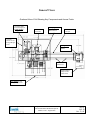
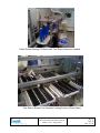
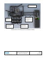
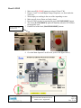
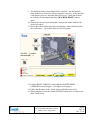
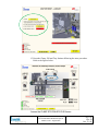
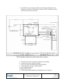
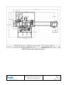
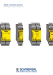
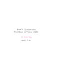
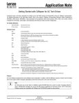
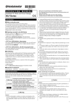
Operation & Maintenance Manual Artisan Automated Production System (AAPS) Operation & Maintenance Manual Artisan Automated Production System Model # 1290 - August 2009 Page 1 Rev D Oct. 23, 09 Table of Contents CHAPTER 2: OVERVIEW .................................................................................. 3 Purpose.................................................................................................................................. 3 Functional Overview ............................................................................................................ 3 General Views ....................................................................................................................... 4 CHAPTER 4: SYSTEM OPERATION .................................................................. 7 Purpose.................................................................................................................................. 7 System Power-up Procedures, E-STOP & Interlocks ......................................................... 7 “Cold” Start Up Procedure .................................................................................................. 7 CHAPTER 5: SYSTEM INSTALLATION .......................................................... 11 Purpose................................................................................................................................ 11 System Installation ............................................................................................................. 11 CHAPTER 9: ATTACHMENTS:........................................................................ 15 Attachments and Appendices ............................................................................................. 15 Operation & Maintenance Manual Artisan Automated Production System Model # 1290 - August 2009 Page 2 Rev D Oct. 23, 09 Chapter 2: Overview Purpose The purpose of this chapter is to familiarize the operator with the functional parts and the layout of the Inventek Engineering Automated Artisan Production System, and to provide an overview of the system operation. The information is provided in the following sections: “Functional Overview” “General Views” Functional Overview The AAPS is designed and intended for the purpose of automatic filling of either the 50 ml or 100 ml (nominal) Artisan Reagent containers. The AAPS consists of a pallet conveyor, which transports an Artisan Reagent Reservoir throughout the production process. The following steps are included in the process: Load/Offload, Fill, Clamp and Assembly, Label, and Label Inspection. Component part loading of the left and right clamps and dispense heads are accomplished from individual feed trays. A Denso six axis Robot is used to pick up each of the three parts from the three feed trays and articulate them into place onto the Artisan Reservoir after the Fill Station. A Universal Labeler is incorporated into the System, and Labels are automatically applied to the Artisan Reservoirs, after which a vision system is used to validate label placement accuracy and that both the Label Bar Code and 2D Matrix Code are readable. Operation & Maintenance Manual Artisan Automated Production System Model # 1290 - August 2009 Page 3 Rev D Oct. 23, 09 General Views Overhead View of Cell Showing Key Components and Access Points Universal Labeler (Print and Apply) at Labeler Station Denso Six Axis Robot Clamping Station and Dispenser Head Insertion Bosch Pallet Conveyor Universal Labeler Access through Hinged Doors Filling Station (Under Fume Hood) Pallet Load and Offload Area Watson Marlow Pumps (Under Fume Hood) Tray Station Access through Hinged Doors Operation & Maintenance Manual Artisan Automated Production System Model # 1290 - August 2009 Page 4 Rev D Oct. 23, 09 Pallet Shown Entering Fill Station with Two Empty Reservoirs Loaded Tray Station Shown From Operator Loading Position (Doors Open) Operation & Maintenance Manual Artisan Automated Production System Model # 1290 - August 2009 Page 5 Rev D Oct. 23, 09 Interlocked Door for Access to Denso Robot and Rear of Labeler Empty Reservoirs are loaded onto Pallets here and Completed Reservoirs are removed from Pallets Interlocked Door for Access to Front of Labeler Interlocked Side Doors for Access to Robot Cell and Inner Tray Station Areas Interlocked Front Doors for Access to Tray Station and Loading of Feed Trays Overhead View of Cell Showing Door and Operator Locations Operation & Maintenance Manual Artisan Automated Production System Model # 1290 - August 2009 Page 6 Rev D Oct. 23, 09 Chapter 4: System Operation Purpose The purpose of this chapter is to familiarize the operator with the system operation of the Artisan Automation Production System. The following topics are covered in these sections: 1. “System Power-up Procedures” 2. “Starts, Stops, & Emergencies” 3. “Operator Console Touch Screen” System Power-up Procedures, E-STOP & Interlocks “Cold” Start Up Procedure Turn “ON” Main Disconnect and Main Switch on front of Main Control Panel. Note: The [E-STOP RESET] Switch and Lamp will not be illuminated at this point. NOTE: If this is a “cold” start up, it may be necessary to open the Main Control Cabinet and Place all Circuit Breakers in the ON position. Operation & Maintenance Manual Artisan Automated Production System Model # 1290 - August 2009 Page 7 Rev D Oct. 23, 09 Reset E-STOP Typical Controls near Access Door(s) 1. Make sure all [E-STOP] buttons are released (Turn CCW). 2. Remove “loose” Left and Right Clamps, Dispensers, etc from inside the work area. 3. Warn employees working in the area of the impending re-start. 4. Make sure all Access Doors are firmly closed. 5. Reset E-STOP circuitry by pressing the green [E-STOP RESET] button. 6. The Green [E-STOP RESET] light will illuminate when the E-STOP has been properly reset. 7. Push all four of the black [MACHINE RESET] buttons. 8. Go to the Main Operator Touch Screen, (refer to the figure below). Operation & Maintenance Manual Artisan Automated Production System Model # 1290 - August 2009 Page 8 Rev D Oct. 23, 09 9. The interlocks in the system should all be “satisfied”, and the interlock status in the lower left corner will turn green for each area. If any interlock is not properly reset it’s interlock status will be red. Check that all doors are securely closed and push the black [MACHINE RESET] buttons again. 10. Turn on the conveyor by touching the Conveyor On control indicated by green circle above. 11. Access the Labeler Status Screen by touching the control indicated by the blue circle above. The Labeler Status Screen will appear. 12. Push the RESET LABELER control and the MASTER RESET – LABELER Screen will appear. (See figure on next page.) 13. Follow the directions on the Touch Screen within the green circle. 14. When completed, touch the yellow RETURN control twice to return to the main Touch Screen. Operation & Maintenance Manual Artisan Automated Production System Model # 1290 - August 2009 Page 9 Rev D Oct. 23, 09 15. Reset the Clamp, Fill and Tray Stations following the same procedure. Refer to the figures below. Access the CLAMP STATION STATUS Screen Operation & Maintenance Manual Artisan Automated Production System Model # 1290 - August 2009 10 Rev D Oct. 23, 09 Page Chapter 5: System Installation Purpose The purpose of this chapter is to provide system installation and setup information. Information is provided in the following section: “System Installation” System Installation Facilitation Requirements: Electrical Power: Main Panel 208 VAC, 60 Hz, 3 phase, 30A CDA – Compressed Air 110 PSI, 3 to 5 CFM, Filtered This section describes the process of installing the AAPS. 1 2 3 Ship crated machine to customer site. Uncrate and inspect all shipping crates for damage. Inspect machine location. For ease of installation, the AAPS is provided with both heavy duty casters and leveling pads. Move the AAPS into position using the supplied casters. Upon locating the AAPS into location use the leveling pads to position the main frames and conveyor. Operation & Maintenance Manual Artisan Automated Production System Model # 1290 - August 2009 11 Rev D Oct. 23, 09 Page 4 Assemble the system starting with the reconnecting the framing. Ensure that there is at least 36” front to back clearance and 30” shoulder clearance in front of the electrical enclosure. AAPS Installation Dimensions with Facility Drop Locations 5 6 7 8 9 10 11 Reconnect all cables, mechanical components, and tubing. Connect main power and other facilities. Power up system and validate interlocks and EMO’s. Confirm operator console is fully operable. Run complete I/O check. Bring system on-line. Confirm that all final alignments and adjustments are complete. Operation & Maintenance Manual Artisan Automated Production System Model # 1290 - August 2009 12 Rev D Oct. 23, 09 Page AAPS Overall Footprint with Dimensions Operation & Maintenance Manual Artisan Automated Production System Model # 1290 - August 2009 13 Rev D Oct. 23, 09 Page AAPS Footprint Dimensions Relevant to Fume Hood Operation & Maintenance Manual Artisan Automated Production System Model # 1290 - August 2009 14 Rev D Oct. 23, 09 Page Chapter 9: Attachments: Attachments and Appendices Electrical Schematics for AAPS 1290 Schematic – AAPS.pdf Spare Parts List for AAPS Spares Parts List - AAPS.pdf Detailed Fabrication Drawings for AAPS Print Out plus PDF Files Assembly Views and Bill of Materials ACAD Files plus Indentured Parts List OEM Technical Literature and Data Sheets (Binder No. 1) Operators and Instruction Manuals for Cognex Insight Micro Vision System and Cognex Checker 3G Vision Sensor Sensor View and Checker Manuals, Insight Explorer Software CD, Checker Software CD and Vision View User Manual. Operators and Maintenance Manuals for DENSO VM-G SCARA Robots. Includes installation and removal instructions for Robot, and preventative maintenance procedures. DENSO Manuals (On a CD) Operation & Maintenance Manual Artisan Automated Production System Model # 1290 - August 2009 15 Rev D Oct. 23, 09 Page DENSO Robot – Safety Precautions Manual OEM Technical Literature and Data Sheets (Binder No. 2) MOXA EtherDevice Switch Installation Guide Safety Precautions and Instruction Bulletins for Omron Components SYSMAC CJ Series Programmable Controllers Instruction Sheet NS10 Touch Screen Instruction Sheet Switching Power Supply Instruction Sheet Remote I/O Terminal Instruction Sheet E3T-ST13 Photoelectric Sensor Instruction Sheet E3X-NA41 Photoelectric Sensor Instruction Sheet E2K-X8MF1 Proximity Switch Instruction Sheet Model D4BL Safety Door Switch Patlite Signal Tower Installation Guide Mounting, Operating and Assembly Instructions for Bosch-Rexroth Conveyor and Components. Lenze Keypad Global Drive Instructions Lenze Drive Motor Mounting Instructions Vario Flow Pallet Assembly Instructions Lateral Guide Assembly Instructions Lateral Guide Holder Assembly Instructions Switch Bracket Assembly Instructions Stop Gate Assembly Instructions Vario Flow Conveyor Assembly Instructions, Operation and Maintenance SMC Digital Pressure Switch Operation Instructions Operation & Maintenance Manual Artisan Automated Production System Model # 1290 - August 2009 16 Rev D Oct. 23, 09 Page Schmersal Safety Interlock Switch Mounting and Wiring Instructions AZ 15/16 Safety Interlock Switch LAZ 15 / AZ 16 Switch Actuators Zebra Print Head and Universal Labeler (Provided by Others) Safety Guide Zebra Print Heads Software and Documentation for Zebra PAX4 Series (On a CD) Label House/Universal APA-II Manual on CD Operation & Maintenance Manual Artisan Automated Production System Model # 1290 - August 2009 17 Rev D Oct. 23, 09 Page