1
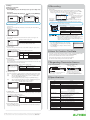
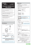
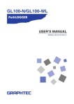
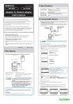
GS-4TSR-UM-151 GS-4TSR For GL100 4ch Thermistor Terminal USER’S MANUAL Thank you very much for buying this GRAPHTEC product. This product can be used as a measurement terminal (hereafter "module") that connects to the GL100-N/GL100-WL. These directions describe preparations and cautions before measurement. To ensure safety, please read the operation instructions, etc. For details on the warnings and how to handle this module, please read the Quick Start Guide or USER'S MANUAL included on the CD-ROM (included in the GL100 packaging) Confirmation of the exterior 2 How To Connect We will now explain how to connect the signal input cable. 1. Thermistor input Connect the GS thermistor sensor (GS-103AT-4P or GS-103JT-4P; each sold separately) to the +/-. Model: GS-103AT-4P Model: GS-103JT-4P (Ultra-thin shape) This terminal is for thermistor input only. Make sure not to input voltage or electric current, as this can cause damage. 4. Logic / pulse input +: No. 1 to No. 4: High-voltage terminal (terminal input on the input signal’s high-voltage side) -: G: Low-voltage terminal (terminal input on the input signal’s low-voltage side) When inserting the cable, insert it while pressing here. G is the GND terminal for this module. After opening the package, please confirm that there are no problems (scratches and dirt) on the exterior before use. 3 Regarding Maximum Input Voltage Confirmation of the attached items. •User’s manual (this book): 1 If by any chance faults are found, please contact the store where you bought the item. * Please note that items mentioned in this book may change without prior notice. To avoid break-downs or short-circuiting accidents, please make sure to abide by the items written below. • Maximum input voltage In case the input voltage exceeds the specifications, the circuit at the input part will break down. Please don't input it. 604309181 MANUAL-TSR Logic / Pulse <Input terminal (+) / GND terminal interval> Maximum input voltage: DC24V 1 Part Names This section describes the name and function of each part. 1. Hook portion 4 How To Measure 1. Power supply (Refer to Quick Start Guide or USER’S MANUAL.) Connect this module while power is being supplied to the GL100 by a battery or USB cable. 2. Input terminal 3. Logic / Pulse input terminal 2. Start-up and operation (1) Screen display menu flow 4. Connector After power-on, the GL100 is ready for operation by holding down [MENU] key. When the module is connected, “Module Type Recognition” screen is displayed. When the module is not connected, “Module Unconnected State” screen is displayed. Operate in accordance with the displayed instructions. 5. Cable packing ࠉࠉࠉ ࠉ㹑㹃㹌㹑㹍㹐ࠉ㹃㹐㹐㹍㹐㸟㸟ࠉࠉࠉࠉࠉࠉ ࠉࠉࠉ ࠉ㹎㹪㹣㹟㹱㹣ࠉ㹡㹭㹬㹬㹣㹡㹲ࠉࠉࠉࠉࠉࠉ ࠉࠉ㹲㹦㹣ࠉ㹱㹣㹬㹱㹭㹰ࠉࠉࠉࠉࠉࠉࠉࠉࠉ 㹏㹓㹇㹒ࠉ㹩㹣㹷ࠉ㹲㹭ࠉ㹎㹭㹵㹣㹰ࠉ㹍㹤㹤 㹀㸿㹒ࠉ㹊㸿㹌ࠉࠉࠉࠉࠉࠉࠉࠉࠉࠉࠉࠉࠉࠉ Module unconnected state <Operation> Connect the module. ࠉࠉࠉࠉࠉࠉࠉࠉࠉࠉࠉࠉࠉࠉࠉࠉࠉࠉࠉࠉࠉ GL100 main module 1. Hook portion .................. 2. Input terminal ................ 3. Logic/Pulse input terminal .......... 4. Connector ..................... Used to mount to a wall. Used to connect Thermistor. Used to input logic / pulse. Used to connect to the connector on the GL100 module. 5. Cable packing ............... This packing is used when connecting the connector. This module is not dustproof or waterproof. Please use it in a proper usage environment. After connecting the GL100 to modules or sensors, please always check/set the time and date. < Extension cable > The module can be used approx. 1.5 m away from the GL100 by using an extension cable for GS (GS-EXC). However, you cannot connect and use multiple extension cables. Recognition of module types ͇㹎㹪㹣㹟㹱㹣ࠉ㹵㹟㹧㹲͇ࠉࠉ ࠉࠉࠉࠉࠉࠉࠉࠉࠉࠉࠉࠉࠉࠉࠉࠉࠉࠉࠉࠉࠉ 㹅㹊㸯㸮㸮㸫㸲㹒㹑㹐ࠉࠉࠉࠉࠉࠉࠉࠉࠉࠉ ࠉࠉࠉ ࠉ㹑㹪㹣㹣㹮㹧㹬㹥㸟㸟ࠉࠉࠉࠉࠉࠉࠉࠉࠉࠉ ࠉ㹃㹌㹒㹃㹐ࠉ㹩㹣㹷ࠉ㹲㹭ࠉ㹱㹲㹟㹰㹲ࠉࠉ 㹏㹓㹇㹒ࠉ㹩㹣㹷ࠉ㹲㹭ࠉ㹎㹭㹵㹣㹰ࠉ㹍㹤㹤 㹀㸿㹒ࠉ㹊㸿㹌ࠉࠉࠉࠉࠉࠉࠉࠉࠉࠉࠉࠉࠉࠉ Standby state <Operation> Press [ENTER] key. ࠉࠉࠉࠉࠉࠉࠉࠉࠉࠉࠉࠉࠉࠉࠉࠉࠉࠉࠉࠉࠉ Module start-up ࠉ㹅㹊㸯㸮㸮㸫㸲㹒㹑㹐ࠉࠉࠉࠉࠉ ࠉ㹇㹬㹧㹲㹧㹟㹪㹧㹸㹧㹬㹥ࠉࠉ ࠉࠉࠉࠉࠉࠉࠉࠉࠉࠉࠉࠉࠉࠉࠉࠉࠉࠉࠉࠉࠉ (2) Free-running screen 㹑㹒㹍㹎ࠉࠉࠉ㸿㹊㹋㸬ࠉࠉࠉࠉࠉࠉ㸯㸸㸰㸶 ࠉࠉ㸩㸱㸲㸬㸯Υࠉࠉࠉ㹊㸸㹍㹄㹄 ࠉࠉ㸩㸲㸮㸬㸰Υࠉࠉࠉ㹊㸸㹍㹄㹄 ࠉࠉ㸩㸳㸮㸬㸱Υࠉࠉࠉ㹊㸸㹍㹄㹄 ࠉࠉ㸩㸱㸲㸬㸲Υࠉࠉࠉ㹊㸸㹍㹄㹄 㹀㸿㹒ࠉ㹊㸿㹌ࠉ㹑㹂ࠉࠉࠉࠉ㹑㸸ࠉ㸯㸬㸮㹱 Hold down the [QUIT] key (approx. three seconds) to put the module into standby state. When running on batteries, the module will automatically go into standby state after three minutes of no operation. Press the [ENTER] key while in standby state to return to the free-running screen. 3. Setting (1) Setting screen operation Item selecting screen Press the [MENU] key on the free-running screen to go to the setting screen. <How to set> Select the item with the directional keys ( 㹙㸿㹋㹎㹛ࠉࠉࠉࠉࠉࠉࠉࠉࠉࠉࠉࠉ㸯㸭㸯㸮 㹁㹆ࠉࠉࠉ㹇㹬㹮㹳㹲ࠉࠉࠉࠉࠉࠉࠉࠉࠉࠉࠉ 㸿㹊㹊㸸ࠉ㹍㹬㸦㸿㸧ࠉࠉࠉࠉࠉࠉࠉࠉࠉࠉۃ 㸯㸸ࠉ㹍㹬㸦㸿㸧ࠉࠉࠉࠉࠉࠉࠉࠉࠉࠉۃ 㸰㸸ࠉ㹍㹬㸦㸿㸧ࠉࠉࠉࠉࠉࠉࠉࠉࠉࠉۃ 㸱㸸ࠉ㹍㹬㸦㸿㸧ࠉࠉࠉࠉࠉࠉࠉࠉࠉࠉۃ 㸲㸸ࠉ㹍㹬㸦㸿㸧ࠉࠉࠉࠉࠉࠉࠉࠉࠉࠉۃ If the submenu shows ) and press the [ENTER] key. 㹙㹂㸿㹒㸿㹛ࠉࠉࠉࠉࠉࠉࠉࠉࠉࠉࠉ㸱㸭㸯㸮 㹑㹟㹫㹮㹪㹧㹬㹥㸸㸯㹱ࠉࠉࠉࠉࠉࠉࠉࠉࠉۃ 㹁㹟㹮㹲㹳㹰㹣ࠉ㹋㹍㹂㹃㸸㹁㹍㹌㹒㸬ࠉࠉۃ 㹁㹟㹮㹲㹳㹰㹣ࠉ㹂㹃㹑㹒㸸㹑㹂ࠉ㹁㹟㹰㹢ۃ 㹄㹰㹣㹣ࠉ㹁㸿㹎㸿㸸㸲㸷㸶㸯㸶㸮ࠉࠉࠉࠉ ࠉࠉࠉࠉࠉࠉࠉ ࠉ㹍㹬㸦㸿㸧ࠉ ࠉ㹍㹬㸦㹈㸧ࠉ ࠉ㹍㹤㹤ࠉࠉࠉ ࠉࠉࠉࠉࠉࠉࠉ ࠉࠉࠉࠉࠉࠉࠉ ࠉࠉࠉࠉࠉࠉࠉ ࠉࠉࠉЌࠉࠉࠉ ࠉ㸯㹱ࠉࠉࠉࠉ ࠉ㸰㹱ࠉࠉࠉࠉ ࠉ㸱㹱ࠉࠉࠉࠉ ࠉ㸴㹱ࠉࠉࠉࠉ ࠉ㸯㸮㹱ࠉࠉࠉ ࠉࠉࠉЎࠉࠉࠉ then there are selections in those directions. 5 Recording (1) Recording Press the [START/STOP] key to start measuring with the set conditions. After pressing [START] key, when the module is in awaiting recording start, “ARMED” is displayed, and then when recording is started, "REC" is displayed. When alarm occurs, “ALM” is displayed. 㹐㹃㹁㸬ࠉࠉࠉ㸿㹊㹋㸬ࠉࠉࠉࠉࠉࠉ㸯㸸㸰㸶 Current time ࠉࠉ㸩㸱㸲㸬㸯Υࠉࠉࠉ㹊㸸㹍㹄㹄 Note: The current time display can be ࠉࠉ㸩㸲㸮㸬㸰Υࠉࠉࠉ㹊㸸㹍㹄㹄 switched to the elapsed time ࠉࠉ㸩㸳㸮㸬㸱Υࠉࠉࠉ㹊㸸㹍㹄㹄 with the [QUIT] key when ࠉࠉ㸩㸱㸲㸬㸲Υࠉࠉࠉ㹊㸸㹍㹄㹄 recording. 㹀㸿㹒ࠉ㹊㸿㹌ࠉ㹑㹂ࠉࠉࠉࠉ㹑㸸ࠉ㸯㸬㸮㹱 When battery Sampling interval replacement “SD” is displayed during accessing the SD card. is required, “BAT” is displayed. LAN: displayed when the wireless LAN connection is enabled. The module’s status is shown with the lamp display. Numerical entry screen <How to set> Numbers can be inputted by increasing or decreasing the value with the and keys. STATUS (Orange) Accessing SD card Low battery Alarm active POWER(Green) 㹙㹂㹟㹲㹣㸭㹒㹧㹫㹣㹛ࠉࠉࠉࠉࠉࠉ㸵㸭㸯㸮 㹒㹷㹮㹣㸸ࠉ㹗㹗㸸㹋㹋㸸㹂㹂ࠉࠉࠉࠉࠉࠉۃ 㹂㹟㹲㹣㸸ࠉ㸰㸮㸯㸲㸫㸮㸯㸫㸮㸲ࠉࠉࠉࠉࠉ 㹒㹧㹫㹣㸸ࠉࠉ㸮㸱㸸㸯㸶㸸㸰㸴ࠉࠉࠉࠉࠉۃ ࠉࠉࠉࠉ ࠉࠉࠉࠉ ࠉࠉࠉࠉ Power supplying Wireless LAN connection possible status Select the 4ch measurement content then select the sensor type to be connected. Batteries cannot be replaced when recording data. Replace them after the recording has finished. AMP input condition settings (4ch) Input Off, On(A), On(J) Set to On (A) for Model GS-103AT-4P. Set to On (J) for Model GS-103JT-4P. (3) LOGIC setting Flash once every 10 seconds Flash once every 5 seconds accessing an SD card, do not remove the SD card. The data • When may not write properly or the SD card may be damaged. When “low battery” is displayed, replace the battery or connect the • USB interface to supply power as soon as possible. Caution: (2) AMP setting 㹙㸿㹋㹎㹛ࠉࠉࠉࠉࠉࠉࠉࠉࠉࠉࠉࠉ㸯㸭㸯㸮 㹁㹆ࠉࠉࠉ㹇㹬㹮㹳㹲ࠉࠉࠉࠉࠉࠉࠉࠉࠉࠉࠉ 㸿㹊㹊㸸ࠉ㹍㹬㸦㸿㸧ࠉࠉࠉࠉࠉࠉࠉࠉࠉࠉۃ 㸯㸸ࠉ㹍㹬㸦㸿㸧ࠉࠉࠉࠉࠉࠉࠉࠉࠉࠉۃ 㸰㸸ࠉ㹍㹬㸦㸿㸧ࠉࠉࠉࠉࠉࠉࠉࠉࠉࠉۃ 㸱㸸ࠉ㹍㹬㸦㸿㸧ࠉࠉࠉࠉࠉࠉࠉࠉࠉࠉۃ 㸲㸸ࠉ㹍㹬㸦㸿㸧ࠉࠉࠉࠉࠉࠉࠉࠉࠉࠉۃ Access light Flash once every 5 seconds Flash once every 10 seconds (2) Recording completion • Press the [START/STOP] key to stop measuring. • The screen display will change to the standby screen display. • Press [ENTER] key to change to the free-running screen display. 㹅㹊㸯㸮㸮㸫㸲㹒㹑㹐ࠉࠉࠉࠉࠉࠉࠉࠉࠉࠉ ࠉࠉࠉ ࠉ㹑㹪㹣㹣㹮㹧㹬㹥㸟㸟ࠉࠉࠉࠉࠉࠉࠉࠉࠉࠉ ࠉ㹃㹌㹒㹃㹐ࠉ㹩㹣㹷ࠉ㹲㹭ࠉ㹱㹲㹟㹰㹲ࠉࠉ 㹏㹓㹇㹒ࠉ㹩㹣㹷ࠉ㹲㹭ࠉ㹎㹭㹵㹣㹰ࠉ㹍㹤㹤 㹀㸿㹒ࠉ㹊㸿㹌ࠉࠉࠉࠉࠉࠉࠉࠉࠉࠉࠉࠉࠉࠉ Select the 4ch logic measurement content. When setting the pulse, select the slope if new logic is “on.” 6 How To Confirm The Data LOGIC input condition settings (4ch) Off LOGIC Pulse Input Slope Input Slope Off, On Off Counts Inst. H, H, L L (4) DATA setting Set the Sampling and Capture Mode those will be recorded to the data recording media. The recorded data’s size will be displayed in the information for the SD card being recorded to. Please take note of it. 㹙㹂㸿㹒㸿㹛ࠉࠉࠉࠉࠉࠉࠉࠉࠉࠉࠉ㸱㸭㸯㸮 㹑㹟㹫㹮㹪㹧㹬㹥㸸㸯㹱ࠉࠉࠉࠉࠉࠉࠉࠉࠉۃ 㹁㹟㹮㹲㹳㹰㹣ࠉ㹋㹍㹂㹃㸸㹁㹍㹌㹒㸬ࠉࠉۃ 㹁㹟㹮㹲㹳㹰㹣ࠉ㹂㹇㹑㹒㸸㹑㹂ࠉ㹁㹟㹰㹢ۃ 㹄㹰㹣㹣ࠉ㹁㸿㹎㸿㸸㸲㸷㸶㸯㸶㸮ࠉࠉࠉࠉ DATA recording condition setting Sampling Capture MODE Capture DIST 500 ms, 1, 2, 5, 10, 20, 30s, 1, 2, 5, 10, 20, 30, 60 min CONT, 1 Hour, 24 Hour Memory, SD card Check the recorded data with the application software included with this module using the method below (for details, refer to the USER'S MANUAL). (1) Connect the USB interface and check the online data (2) Insert the SD card into PC and check the data directly (3) Check the data directly from PC via wireless LAN 7 Regarding Thermistor Sensor 1. Type A (GS-103A-4P) 2. Type J (GS-103JT-4P) Approx. 15 mm Approx. 3,000 mm Approx. 5 mm Select the conditions for beginning data recording after measurement starts. Off Start Stop : Pressing the [START/STOP] key on this module will start/stop recording. : The recording will start with the trigger source conditions after pressing the [START/STOP] key. The recording will stop after pressing the [START/STOP] key. : The recording will start after pressing the [START/STOP] key and will be stopped with the trigger source conditions. 㹙㹒㹐㹇㹅㹅㹃㹐㹛ࠉࠉࠉࠉࠉࠉࠉࠉ㸲㸭㸯㸮 㹒㹐㹇㹅ࠉ㹑㹣㹲㹲㹧㹬㹥㸸㹍㹤㹤ࠉࠉࠉࠉۃ 㹒㹐㹇㹅ࠉ㹑㹭㹳㹰㹡㹣㸸㹍㹤㹤ࠉࠉࠉࠉࠉۃ ࠉࠉࠉࠉࠉ TRIGGER capture condition settings TRIG Setting TRIG Source Off, Start, Stop Off Level Off / Mode Level H Value setting L * The level depends on the setting range. Alarm Date Date, Time • Insulation resistance : DC500V 100MΩ or more • Withstand voltage : AC100V 1 min. 㹙㸿㹊㸿㹐㹋㹛ࠉࠉࠉࠉࠉࠉࠉࠉࠉࠉ㸳㸭㸯㸮 㸿㹪㹟㹰㹫㸸㹍㹤㹤ࠉࠉࠉࠉࠉࠉࠉࠉࠉࠉࠉۃ ࠉࠉࠉࠉࠉࠉ ࠉࠉࠉࠉࠉ Item Measurement data Measurement channels Input method Measurement temperature range Measured temperature accuracy Logic•Pulse Input ALARM settings Alarm Off Level / Mode Pulse measurement range Off Level H Value setting L * The level depends on the setting range. Temperature unit Sampling interval Triggers (7) Temperature unit setting From the OTHER-2 screen, you can switch between temperature displays in Celsius (°C) or Fahrenheit (°F). • Insulation resistance: DC500V 100MΩ or more • Withstands voltage: AC100V, 1 min. • Bending: 90° bending each wire once Note: Make sure not to apply external force to the device when the thermistor sensor is bent. 8 Specifications (6) ALARM setting Set the alarm information. The parameters will vary depending on the setting range. Please set the number level. Approx. 3,000 mm Element section Approx. 6 mm (5) TRIGGER setting <Ultra-thin shape> Alarm Cable length Usage environment External dimensions [W×D×H] (approximate) Weight (approximate) Contents Temperature/Logic, Pulse count (Instant, Accumulation) Temperature 4 channels Logic/Pulse count 4 channels Scan method, non-isolated input (Thermistor input) Available for the two types of thermistors (option). Type A: -40°C to 105°C (GS-103AT-4P) Type J: -40°C to 120°C (GS-103JT-4P) <Main module> -40 ≤ TS < 0 ±0.7 (°C) 0 ≤ TS ≤ 35 ±0.2 (°C) 35 < TS ≤ 70 ±0.4 (°C) 70 < TS ≤ 120 ±1.0 (°C) <Thermistor sensor> ±0.4 °C (Typical value) Input voltage range: 0 to +24V (One line ground input) Input signal: No-voltage contact (a contact, b contact, NO, NC), Open collector, voltage input Threshold level: approx. +2.5V Hysteresis: approx. 0.5V (+2 to +2.5V) Instant : Max. 200C / Sampling Accumulation: Max. 65535C Select from °C (Celsius) / °F (Fahrenheit) 0.5, 1, 2, 5, 10, 20, 30 sec. 1, 2, 5, 10, 20, 30, 60 min. Start trigger : OFF, LEVEL, ALARAM, DATE Stop trigger : OFF, LEVEL, ALARAM OFF / Level approximate 20 cm -10 to 50°C, 80% RH or less (non-condensing) 46 × 66 × 35.5 mm (not including protruding parts) 83 g August 1, 2014 ALTHEN GmbH Meß- und Sensortechnik | Frankfurter Straße 150-152 | 65779 Kelkheim Tel.: +49 (0) 61 95- 70 06 0 | Fax: +49 (0) 61 95- 70 06 66 | [email protected] | althen.de © ALTHEN GmbH 2014 㹙㹊㹍㹅㹇㹁㹛ࠉࠉࠉࠉࠉࠉࠉࠉࠉࠉ㸰㸭㸯㸮 㹇㹬㹮㹳㹲ࠉ㹋㹭㹢㹣㸸ࠉ㹍㹤㹤ࠉࠉࠉࠉࠉۃ 㹁㹆㸸㹇㹬㹮㹳㹲ࠉ㹑㹪㹭㹮㹣ࠉࠉࠉࠉࠉࠉࠉ 㸯㸸ࠉࠉࠉࠉࠉࠉࠉࠉࠉࠉࠉࠉࠉࠉࠉࠉࠉࠉ 㸰㸸ࠉࠉࠉࠉࠉࠉࠉࠉࠉࠉࠉࠉࠉࠉࠉࠉࠉࠉ 㸱㸸ࠉࠉࠉࠉࠉࠉࠉࠉࠉࠉࠉࠉࠉࠉࠉࠉࠉࠉ 㸲㸸ࠉࠉࠉࠉࠉࠉࠉࠉࠉࠉࠉࠉࠉࠉࠉࠉࠉࠉ