1
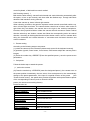
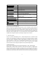
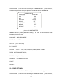
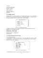
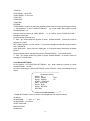
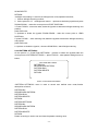
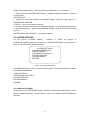
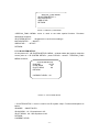
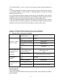
IR&intelligent speed dome
User manual
※You must read the manual carefully before using,please take care of it,so you can consult as you need.
Catalogue
chapter 1 foreword .................................................................................................................................... 3
chapter 2 product summarize ................................................................................................................ 3
2.1 product profile ................................................................................................................................ 3
2.2 capability feature ............................................................................................................................ 4
2.3 function description ........................................................................................................................ 4
2.4 technical parameters ........................................................................................................................ 6
chapter 3
installation ......................................................................................................................................... 7
3.1 dome camera DIP switch setting ........................................................................................................................ 7
3.1.1 enter to DIP switch setting ...................................................................................................................... 7
3.1.2 DIP switch setting................................................................................................................................. 7
3.2 installation of IR&intelligent speed dome ................................................................................................... 10
3.2.1the sizes of dome and bracket .......................................................................................................... 10
3.2.2 the installation of dome and bracket ..................................................................................................... 11
chapter 4 basic operation of dome .................................................................................................... 11
chapter 5 menu setting .......................................................................................................................... 14
5.1 main menu ................................................................................................................................................... 15
5.2 < CAMERA SETTINGS >(zoom parameters setting) ...................................................................... 15
5.3 <DOME SETTINGS>(dome setting) ..................................................................................................... 16
5.4 < FUNCTION SETTINGS >(function setting) ................................................................................... 17
5.4.1<PRESET SETUP>(presets setting) ........................................................................................................ 18
5.4.2<TOUR SETTINGS>(cruise setting) ........................................................................................................ 18
5.4.3<SCAN SETTINGS>(scanning setting) ................................................................................................... 19
5.4.4<PATTERN SETTINGS>(patrol track setting) ........................................................................................ 20
5.5 SYSTEM SETTINGS(system setting)menu ......................................................................................... 21
5.5.1 DISPLAY SETTINGS (show setting):...................................................................................................... 21
5.6 CLEARANCE SETTINGS (eliminate setting): .......................................................................................... 22
5.7 SPECIAL_FUNC MENU (special function menu): ................................................................................... 22
5.7.1 IR SYSTEM SETUP (IR system setting): ............................................................................................... 22
chapter 6 Simple fault clearing form and maintain ...................................................................... 23
6.1 Simple fault clearing form ............................................................................................................................... 23
6.2 notes................................................................................................................................................................ 24
6.3 after service .................................................................................................................................................... 25
-2-
Chapter 1 foreword
At the start of the installation and use of infrared intelligent high-speed dome (hereinafter referred to as
"dome" ) before, please read the following information:
1. Before installation, please read carefully the product manuals and installation guide.
2. Do not put products in unstable plane test, such as the installation of operation, in before operation to
ensure the machine put smoothly and assembly firmly.
3. Transportation and storage process to prevent stress, violent vibration and soaking etc of product
damage.
4. This product will not reversed installation; For high-speed dome to handled with care, don't push hard on
the various structural components, or it may cause a mechanical problem, affects the high-speed dome
overall performance. High-speed dome lens front transparent material belongs to advanced optical
materials, avoid to use the hand directly touch, lest cause scratches, affects the image quality.
5. Do not send any solid object or fluid substance penetrated machine, lest damage machine.
6. Wiring must observe the electrical safety standard, use this machine to bring special power supply. This
product rs-five 485 video signal and using TVS level prevent lightning technique can effectively prevent
500W below power by lightning, surge and other kinds of pulse signal of equipment damage. Video signal
rs-five 485 and during transmission with high pressure equipment or cable should keep sufficient distance,
when necessary even prepare necessary lightning, prevent surge protection.
7. Whether used or not in use, never can make camera aimed at the brightness of the sun or other objects.
Or you could make CCD permanent damage.
8. Don't use it beyond standard of environmental temperature, humidity.
9 in this product within and no user serviceable parts. When the machine is a fault, not easily to machine
any repair operations, should first and specifications found fault, find no fault reason is ask professional
maintenance. Relevant maintenance work, must by my company authorized maintenance inspection
organizations
chapter 2 product summarize
2.1 product introduction
Infrared intelligent high-speed ball is used in today's latest of scientific and technological achievements, the
sophistication of manufacturing process, Comprehensive years of experience of the successful
development of automatic zoom lens, configuration of high-performance digital signal processing (DSP)
camera, Set the built-in yuntai and digital decoder integrated, represents a new generation of high
technology to monitor the product development trend. It adopts full digital control, mechanical exquisite
design simple, can be arbitrary quickly positioning and continuous tracing scanning, with automatic tracking
the camera, realizing function in the true sense of all-round, without the blind spot of the intelligent
surveillance, Can automatically adapt to the environment of light and shade and target near-far changes,
-3-
High reliability, long and stable operation, maintenance unnecessary.
Infrared intelligent high-speed ball combines various control protocol, can support a variety of popular
system platform. With other system matching, each system connection and method of use not identical,
here do not specify, please contact the relevant system manufacturer or dealer contact to get necessary
information.
Infrared intelligent high-speed ball of various characteristics of large area, applicable to all walks of life
activities target surveillance. Such as power systems, telecom departments, bank security, mines,
intelligent building, intelligent community, city road monitoring, airports, railway stations, etc as security
monitoring situation, and the fire monitoring system of image monitoring equipment.
2.2 performance characteristics
1. Built-in OSD English onscreen menu, via the menu to display and change the ball machine information
and parameters can be set and call preset point, figure scanning, regional scanning and display area, etc.
2. Integrated design, compact structure, high reliability.
3. 255 preset points.
4. Adopt RS485 bus control.
5. Precision of motor drive, smooth operation, senstive reaction.
6. Level 360 ° continuous rotation, no monitoring blind spots.
7. Rotation speed camera variable times according to automatically adjust multiples,
8. 90 °, automatic vertical flipping 180 ° after continuous monitoring.
9. Automatic focus, automatic white balance.
10. Backlighting compensation function, have strong illuminant environment can see all the objects.
11. Combines various control protocol, baud rate is adjustable.
12. Wide dynamic camera support (SONY1010, SONY990) SONY490,
2.3 functional specification
Below briefly introduce infrared intelligent high-speed ball's main function, and describes the various
functions and operating the general principles, don't involve concrete operating methods.
1 set address coding, baud rate, control protocol
Any operation command has its target camera address coding, baud rate, control protocol, single camera
just response to their own address coding, baud rate, control protocol consistent operation orders. Camera
address coding, baud rate, control protocol specific setting methods please refer to dial the code Settings.
2 the target tracking.
The user can use the control on keyboard rocker control the camera up, down, left and right rotation, could
be used to track a moving target or mobile horizon, another can adjust focal length to change perspective
size or target image size. In automatic focus condition, with the rotation of the lens, cameras automatically
on the scenery changing quickly adjust, instant get a clear picture.
3. Focal length/speed automatic matching technology
Manual adjustment, focus the long ball machine, high-speed reflect make slight touches rocker may makes
the picture is moving, thereby causing loss of data. Based on the humanized design, intelligent ball focal
distance according to automatically adjust camera horizontal and vertical speed, make manual operation is
more easy target tracking.
Automatic flip 4.
The operator will lens pull bottom (vertical) if you still hold rocker, right now lens level automatically rotate
for 180 ° immediately after 90 °, upturned blade can be directly to watch on the back of the scenery, so as
-4-
to realize the longitudinal 180 ° throughoutthe continuous monitoring.
5. Setting and call preset position
Presets feature is the ball under the current state of functions of the horizontal Angle, yuntai Angle and
camera position such as parameters storage focal length into memory, when need can rapidly and will call
these parameters to adjust the yuntai and camera position. The operator can be quickly through controlling
the keyboard, infrared controller etc control equipment storage and calling the preset point, ball machine
support 256 preset points.
Lens control 6.
(1) the focal length of control
Users can through ball machine control keyboard or matrix host zooming unhealthily, to obtain the required
a panoramic view of the screen, or are subtle view.
(2) focus control
The system default auto-focusing, zoom, a camera in the center of autofocus scenery pictures, keep clear
image; Under special circumstances, the user can manual focus to hope image effects.
When exposed to manual focus condition, to restore auto-focusing, just shake analog stick can recover
automatic focus. Another can also send special control command or call an arbitrary preset bits of recovery
auto-focusing method.
A camera under the following circumstances will not be able to camera target auto-focusing:
A. goal is not a picture center;
B. targets at the far and near the place,
C. target for light objects, such as luminous objects such as NaiDeng, spot,
D. goal in with water or dust behind glass,
E. target move too quickly,
F. area of the target, such as wall,
G. goal too dark or was vague.
Aperture control. 7.
Users can through controlling the keyboard, manually adjust aperture size, to obtain the required picture
brightness.
8. Automatic backlighting compensation
When backlit compensation function opened, the camera can be automatically when light under the
background of darker targets brightness compensation. To light the background of daylighting adjustment,
and avoid background illumination and cause the whole picture posse shining, but through dark and target,
thus obtains not discern clear images.
9. Auto white balance
According to the environment radial change, automatic adjustment, reproduce true colors.
10. Night vision function (color b&w conversion)
With night vision function of camera, in automatic color b&w conversion mode, can according to the
environment of the light changes automatically converts CCD intensity of illumination. Such as: during the
day because of the light is enough, use general illumination guarantee colourful picture. But at night can
automatically change for a low illumination, with black and white pictures showed clear scenery.
11. Automatic cruise
Through a preset cruise preset point, which will be certain preset click request order to automatic
arrangement cruise queue, only one external commands can let indoor medium-speed ball automatically
set according to the preset point order defined intervals reciprocating kept movement.
12. Figure scan
Figure scan is through the menu will ball chance done by track storage down on electricity action, free
-5-
action, alarm linkage, etc to invoke the store scan route.
13. Scanned continuously
Only an external command or through action, free action on electricity, alarm linkage, etc to call, can make
the ball with a certain speed machine horizontal continuous cycle scan.
14. Intermittent scan
Only an external command or through action, free action on electricity, alarm linkage, etc to call, can make
the ball with a certain speed machine horizontal batch of circulation scan.
15. Regional scan
Only an external command or through action, free action on electricity, alarm linkage, etc to call, can make
the ball with certain horizontal machine speed, set range between scan.
16. Wide dynamic
Support SONY newest FCB - EC490, EC990 FCB - FCB - EC1010 wide, dynamic camera, applicable in
strong backlight environment of applicable.
2.4 Technical parameters
Model No.:
Image sensor
Signal model
Horizontal
resolution
Effective pixel
Minimum
illumination
S/N radio
Backlight
compensation
White balance
Electronic shutter
Focus length
Optical focus
Focus
Presets
Patrol track
Cruise track
Other scan
Rotation range
Rotation speed
Communications
OSD
Special function
PTZ 7H450
1/4" CCD
NTSC
540TVL
768(H) x 494(V)
0LUX(with IR), Color to B/W, with IR-CUT function
≥52dB(Enhanced)
On/Off
Auto
1/50~1/12000 seconds
3.0~90.0mm
27X
Auto/manual, take high-performance DSP to realize
complete digit and ultra-high speed focus function
256
4groups, each can record 200 actions
8 groups, every group have 30 presets can join cruise, can
setting the presets' residence time
4 groups, Support Horizontal scan, deuce area scan, scan
random
Horizontal 360°unlimted rotation, Vertical 90°,auto
reversal
Horizontal & Vertical Min 0.01°,Max 200°/S
RS-485, PELCO D, PELCO P
Whole screen Chinese / english menu
AWB, MASK, DNR, Strong light Optimizer, MIRROR,
-6-
Temperature
control
Intelligent IR lamps
Power supply
Material
Work environment
DSS
built-in
150m, auto-switch the IR distance according to the focus
of camera or force to turn on/off the IR lamps through
software.
AC24V/4A
Aluminum shell,waterproof IP66
-20℃~+50℃(select temperature control accessories),
<95%RH
chapter 3 installation
3.1 dome camera DIP switch setting
Infrared intelligent high-speed dome combines various control protocol, baud rate can adjust, can
compatible more monitoring system. In a fixed installation ball machine before, according to need to dial
the code switch is adjusted to the corresponding coding, to change the ball machine baud rate, control
protocol, address coding. If no special requirements, ball machine factory address coding default values for
"1", baud rate is set to "2400BPS" corresponding coding, control protocol is set to "PELCO - D" agreement
the corresponding coding.
3.1.1 enter to DIP switch setting
Open the ball machine front-end dial the code cover, as shown in picture 1. Through dial the code switch to
alter ball machine "BAUD RATE (BAUD - RATE)", "control PROTOCOL (PROTOCOL)" and "ADDRESS
coding (after)". Dial the code switch diagram, as picture 2 shows.
picture 1 DIP switch cover
3.1.2 DIP switch setting
picture 2 DIP switch
SW1 swich:Baud rate and control protocol switch
SW2 swich:Address DIP switch
Dial the code switch to "ON" means "1", dial the code switch to "OFF" means "0", dial the code switch ON
the left and right for low to high
Baud rate and control protocol Settings list:
SW1
Number
Control
protocol
1
2
3
4
OFF
OFF
PELCO-P/D self-adaption
ON
OFF
PELCO-P/D self-adaption
OFF
ON
Save
-7-
ON
ON
Save
Baud
rate
OFF
OFF
2400
ON
OFF
4800
(BPS)
OFF
ON
9600
ON
ON
19200
2. SW2 Switch sets the ball machine address coding. Address set by binary mode, total can set 256
different address coding, see ball machine address coding sheets. Factory default Settings as shown in
figure 2.
SW2dome address encode table
Dome
address
0
1
2
3
4
5
6
7
8
OFF
OFF
OFF
OFF
OFF
OFF
OFF
OFF
1
ON
OFF
OFF
OFF
OFF
OFF
OFF
OFF
2
OFF
ON
OFF
OFF
OFF
OFF
OFF
OFF
3
ON
ON
OFF
OFF
OFF
OFF
OFF
OFF
4
OFF
OFF
ON
OFF
OFF
OFF
OFF
OFF
5
ON
OFF
ON
OFF
OFF
OFF
OFF
OFF
6
OFF
ON
ON
OFF
OFF
OFF
OFF
OFF
7
ON
ON
ON
OFF
OFF
OFF
OFF
OFF
8
OFF
OFF
OFF
ON
OFF
OFF
OFF
OFF
9
ON
OFF
OFF
ON
OFF
OFF
OFF
OFF
10
OFF
ON
OFF
ON
OFF
OFF
OFF
OFF
11
ON
ON
OFF
ON
OFF
OFF
OFF
OFF
12
OFF
OFF
ON
ON
OFF
OFF
OFF
OFF
13
ON
OFF
ON
ON
OFF
OFF
OFF
OFF
14
OFF
ON
ON
ON
OFF
OFF
OFF
OFF
15
ON
ON
ON
ON
OFF
OFF
OFF
OFF
16
OFF
OFF
OFF
OFF
ON
OFF
OFF
OFF
17
18
ON
OFF
OFF
ON
OFF
OFF
OFF
OFF
ON
ON
OFF
OFF
OFF
OFF
OFF
OFF
19
ON
ON
OFF
OFF
ON
OFF
OFF
OFF
20
OFF
OFF
ON
OFF
ON
OFF
OFF
OFF
21
ON
OFF
ON
OFF
ON
OFF
OFF
OFF
22
OFF
ON
ON
OFF
ON
OFF
OFF
OFF
23
ON
ON
ON
OFF
ON
OFF
OFF
OFF
24
OFF
OFF
OFF
ON
ON
OFF
OFF
OFF
25
ON
OFF
OFF
ON
ON
OFF
OFF
OFF
26
OFF
ON
OFF
ON
ON
OFF
OFF
OFF
27
ON
ON
OFF
ON
ON
OFF
OFF
OFF
28
OFF
OFF
ON
ON
ON
OFF
OFF
OFF
246
OFF
ON
ON
OFF
ON
ON
ON
ON
247
ON
ON
ON
OFF
ON
ON
ON
ON
248
OFF
OFF
OFF
ON
ON
ON
ON
ON
-8-
249
ON
OFF
OFF
ON
ON
ON
ON
ON
250
OFF
ON
OFF
ON
ON
ON
ON
ON
251
ON
ON
OFF
ON
ON
ON
ON
ON
252
OFF
OFF
ON
ON
ON
ON
ON
ON
253
ON
OFF
ON
ON
ON
ON
ON
ON
254
OFF
ON
ON
ON
ON
ON
ON
ON
255
ON
ON
ON
ON
ON
ON
ON
ON
-9-
3.2 installation of IR&intelligent speed dome
3.2.1the sizes of dome and bracket
Product diagram 3-1
picture 3-1
The demension of bracket 3-2
picture 3-2
- 10 -
3.2.2 the installation of dome and bracket
Step 1:the installation of bracket
picture 3-3
Determine the screw holes position
picture 3-5 drilled the holes
picture 3-4 drilling In the position
picture3-6
Tighten the screw
In stay on the wall of ball machine installation, according to determine the installation
position stent screw holes position with signal pen on wall draw hole position as shown in
FIG. 3-3. On wall drilling as shown in figure 3-4. The expansion bolts into the hole, Will
cable through stents, then on the support screw holes on the nuts tighten the screw, as
shown in figure 3-6.
Step 2: the ball machine installation
Stents three screw loose on the cover, the ball will be machine head alignment teams,
tighten the scaffolds overhead into three fixed screw, in case the ball machine off.
chapter 4 basic operation of dome
Due to the different system platform specific operation method, generally should not
identical with system manufacturer operation manual shall prevail, different circumstances
will have special requirements and operation method, please contact with dealers get
necessary information. Here only introduced connection this company produces the
- 11 -
control keyboard, of ball machine control method.
Self-checking electrify. 1.
Ball machine after electrify, camera first horizontal and vertical direction automatically after
the sports, in lens to pull recently, and down after the farthest stop. Through self-check
determine ball machine running normally.
Control the camera up, down, left and right rotation:
When choosing a camera, can pass the keyboard rocker manual control ball machine up,
down, left and right movement. The camera shake control lever of action, when rocker to
right when they are shaken, the camera also to the right in the northern hemisphere.
Likewise, when joystick left when I shake the camera also left movement. Rocker vertical
direction when they are shaken, camera also follow the corresponding action do vertical
direction. According to the diagonal direction when shaken rocker, can let a camera while
doing the horizontal and vertical direction of movement and movement direction and
rocker consistent.
2.Presets setting
According to the following steps to set preset :
(1) select the camera (more information please read control of the keyboard manual);
(2) operation joystick, zoom button, focus button, IRIS buttons adjust the camera picture
images;
(3) Press the number key +PRESET (Enter the specified preset ), save the preset scene
parameters.
3.Call preset
Follow the below step to watch the preset:
(1)select the camera;
(2) Press the number key +PREVIEW (enter the designated preset ), the camera move to
the preset position immediately, the lens zoom, focus and aperture is also automatically
change to the preset parameters; if the input is a special function of the preset
(see
"Preset function menu"), the speed dome camera will perform with special features preset
of the corresponding functions (such as: Enter the 97/99
preset, the camera auto-tracking feature).
Preset function list
CALL COMMANDS
EXECUTE FUNCTION
CALL 64/95 PRESETS
Enter dome camera menu
CALL 57 PRESETS
Enter CAMERA menu
CALL 56 PRESETS/IRIS-
Force exit menu
CALL 97/99 PRESETS
Start automatic scan
CALL 96 PRESET OR OTHER
Close automatic scan
PTZ CONTRONL
CALL 32 PRESETS
Start Tour function 1
CALL 53 PRESETS
Start Tour function 2
CALL 49 PRESETS
Start Tour function 3
- 12 -
CALL 50 PRESETS
Start Tour function 4
CALL 58 PRESETS
Pattern scan 1
SET 51 PRESETS
Set left/ right scan 1 -start
SET 52 PRESETS
Set left/ right scan 1 -end
CALL 51 PRESETS
Call left/ right scan 1
CALL 52 PRESETS
Call left/ right scan 2
CALL 93 PRESETS
System restart
CALL 94 PRESETS
Recover the factory parameters
CALL 59 PRESETS
Started four combinations Tour function (Tour preset
expandto 64 pcs)
CALL 100 PRESETS OR 1+F1
Manual open first group of infrared lamp
CALL 100 PRESETS OR 2+F1
Manual open second group of infrared lamp
1+F2
Manual close first group of infrared lamp
2+F2
Manual close second group of infrared lamp
CALL 106 PRESETS
Infrared lamp automatic open mode
4.close-up lens and wide-angle lens
Adjust the camera lens variable times pull away or close, to enlarge or reduce scenery to
feature and wide-angle effect.press ZOOM+ , camera scene will be near,and the object on
the camera image will be 14 zoom in.press ZOOM- ,camera scene will be far, and the
object on the camera image will be zoom out.if you quickly press and loose variable times
buttons,the camera images which is on the monitor will be a little changed.the camera
variable times changed is depend on pressing the length of time of buttons.
5.Lens focus control
Focus is a process that adjusting one of camera image and scen' s resolution. Press
FOCUS+, the long distance of object or scene will be more clear,short distance of object
and scene will be fuzzy,press FOCUS- ,short distance of object and scene will be
clear,long distance of object will be fuzzy.Repeated adjustment focus on key until the
object which one on the monitor is from fuzzy to clear. The same with the variable
times,the camera's focus changed is depend on focus pressed length of time.
6. Manual iris function
IRIS changed the brightness level of camera images,press IRIS+ ,camera image
brighten,press ,camera image will darken.it's same with the buttons of variable times,
camera's bright and dark are depend on length of time you pressing the IRIS buttons.
Chapter 4 menu setting This chapter will be detailed introduction of OSD menu. Switch on
the power, the dome camera, after self monitor screen will show the following information:
- 13 -
chapter 5 menu setting
This chapter will detail OSD menu operation. Switch on the power, ball machine, after the
monitor screen self-checking admiral are shown in the following information:
VERSION:V10.04
PROTOCOL:PELCO-P/D
BAUD RATE:2400
CAMERA ID:1
HORIZONTAL CHECK OK
VERTICAL CHECK OK
CAMERA CHECK OK
These messages will always show the dome camera till self-checking finished.
Due to the different monitoring system for the dome camera is not identical operation
method, the specific operation please contact with dealers.The following simple
introduction to use keyboard control operation of OSD menu.
1. Enter main menu:CALL No.64/ 95 preset,and you will enter OSD main menu.shake left
/right FOCUS+ /FOCUS-Is the enter key. IRIS-(iris close)is the exit key
2.Enter other menu:Up / down shake the joystick, so that the cursor is pointing to a
menu,press FOCUS+ enter the menu.
3.Function select:Up / down shake the joystick or press ZOOM+ / ZOOM-, so that the
cursor is pointing to a menu,press FOCUS+select this function.
4.Parameter select:Up / down shake the joystick or press FOCUS+/ FOCUS- to select
the parameter
5.Restore settings:Press IRIS+ ,restore the settings,it is effective if has corresponding
prompt.
6.Does not restore and back to last menu: press IRIS- back to last menu, it is effective if
has 15 corresponding prompt.
7.Exit menu: Up / down shake the joystick,so that the cursor is pointing to exit
option,press IRIS+exit OSD menu.
8.Back to previous menu:Up / down shake the joystick,so that the cursor is pointing to
back option,press FOCUS+and back to previous menu.
- 14 -
Notes:Different speed dome setting,different display on speed dome.
The following is detailed description of use smart standard control keyboard to operate
OSD menu.
5.1
Main menu
Speed dome work normally,set No.64/95 preset,enter main menu,screen display is as
picture 3.1.
MAIN MENU
CAMERA SETTINGS--- >
DOME SETTINGS --->
FUNCTION SETTINGS--- >
SYSTEM SETTINGS --->
SPECIAL FUNCTION--- >
EXIT
picture 3.1 MAIN MENU
Main menu contents description:
< CAMERA SETUP >:
< DOME SETTINGS >:
< FUNCTION SETTINGS >:
< SYSTEM SETTINGS >:
< SPECIAL FUNCTION >:
<EXIT>:
To enter the menu and execute of the various functions of the basic operation is as
follows:
1 . On the picture 3.1<MAIN MENU> , Up / down shake the joystick or press
ZOOM+/ZOOM-,so that the cursor is pointing to a menu item or function option;
2.Press FOCUS+,enter menu or operate a function option.
5.2
< CAMERA SETUP >(zoom parameters setting)
On the picture 3.1<MAIN MENU> , Up / down shake the joystick or press
- 15 -
ZOOM+/ZOOM-,so that the cursor is pointing to <CAMERA SETUP>,press FOCUS+,
enter camera parameters setting as picture 3.2<CAMERA SETUP> MAIN MENU
CAMERA SETUP
LANGUAGE
ENGLISH
ZOOMDISP
ON
AGC
200
BLC
OFF
SHUTTER
AUTO
FOCUS
AUTO
BRIGHT
130
COLORSEL
AUTO
MIRROR
OFF
LENINIT
---DEFAULT
----
picture 3.2 CAMERA SETUP
CAMERA SETUP ( zoom parameters setting ) is used to check camera basic
information,function as follow.
LANGUAGE:ENGLISH/CHINESE
ZOOMDISP:ON/OFF
AGC:200(160---240/AUTO)
BLC:ON/OFF
SHUTTER :AUTO---(1/50,1/120,1/250,1/500,1/1000,1/2000--1/10000)
FOCUS:AUTO/MANU/KEYAUTO。
BRIGHT: 130(60---170) 。
COLORSEL:AUTO/BLACK/COLOR
LENINIT:
DEFAULT:
5.3 <DOME SETTINGS>
On the picture 3.1 <MAIN MENU> , Up / down shake the joystick or press
ZOOM+/ZOOM-,so that the cursor is pointing to <DOME SETTINGS>,press FOCUS+,
- 16 -
enter dome camera setting as below picture3.3 DOME SETTINGS
DOME SETTINGS
AUTO INVERT
IDLE TIME/MIN
IDLE ACTIVE
ACTIVE No.
REBOO TRUN
RUN No.
RETURN
ON
0
NO
NO
picture 3.3 DOME SETTINGS
On the picture 3.3 DOME SETTINGS , function as below;
DOME SETTINGS
AUTO INVERT
ON/OFF
IDLE TIME/MIN
:0~255, closed:0
IDLE ACTIVE
NO/PRESET/SCAN/PATTERN/TOUR
ACTIVE No.
REBOOT RUN
:NO/PRESET/SCAN/PATTERN/TOUR/LAST STA
RUN No.
RETURN
5.4 < FUNCTION SETTINGS >
On the picture <3.1MAIN MENU>,
Up / down shake the joystick or press ZOOM+/ZOOM-,
so that the cursors pointing to<FUNCTION SETTINGS>,press FOCUS+,enter function
setting menu as below 3.4< FUNCTION SETTINGS>
FUNCTION SETTINGS
PRESET SETUP --->
TOUR SETUP--->
SCAN SETUP--->
PATTERN SETUP--->
RETURN
picture 3.4< FUNCTION SETTINGS >
<FUNCTION SETTINGS> menu is used to set functions, functions as below;
<PRESET SETUP>:
<TOUR SETUP>:
<SCAN SETUP>:
<PATTERN SETUP>:
- 17 -
RETURN:
FUNCTION SETTINGS
PRESET SETUP --->
TOUR SETUP--->
SCAN SETUP--->
PATTERN SETUP--->
RETURN
5.4.1<PRESET SETUP>
Presets setting, the specific operation is as follows: On the picture <3.4< FUNCTION
SETTINGS >,Up / down shake the joystick or pressZOOM+/ZOOM-,so that the cursor is
pointing to<PRESET SETUP>;press FOCUS+,enter as below:
PRESET SETTINGS
PRESET No.
1
PRESET SET
PRESET CALL
PRESET DELETE
RETURN
Picture 3.4.1 <PRESET SETTINGS >
< PRESET SETTINGS >menu is used to set presets, Functions description as below;
PRESET No.:the number of presets
PRESET SET:presets setting
PRESET CALL:calling resets
PRESET DELETE:relating resets
RETURN:return
5.4.2<TOUR SETTINGS>(cruise setting)
4.4.2<TOUR SETTINGS>
On the picture<3.4 FUNCTION SETTINGS>,Up / down shake the joystick or press
ZOOM+/ZOOM-,so that the cursor is pointing to<TOUR SETTINGS>,press FOCUS+,
enter tour settings menu as below;
TOUR SETTINGS
TOUR No.
1
STAY DELAY
4
TOUR SPEED
63
TOUR SET
TOUR RUN
TOUR DEL
RETURN
Picture 3.4.2< TOUR SETTINGS >
< TOUR SETTINGS >menu is used to set tour , function as below;
- 18 -
TOUR No.:
STAY DELAY:(S):0~255
TOUR SPEED:0~63 level
TOUR SET:
TOUR RUN:
TOUR DEL:
RETURN:
TOUR setting is used to set lens auto execute preset track for scanning.the step as below;
1.On the picture <3.4.2< TOUR SETTINGS > ,Up / down shake the joystick or press
ZOOM+/ZOOM-,so
that the cursor is pointing to <STAY DELAY (S)0~255S],press FOCUS+/FOCUS-,
left/right to shake the
joystick,choose the delay time
2.then,Up / down shake the joystick or press ZOOM+/ZOOM-,so that the cursor is
pointing to <TOUR
SET,press FOCUS+,you can see No. 1~16 presets,left/right to shake the joystick,choose
NO.1 PRESETS
press IRIS+save,return the menu setting No. 2~16 presets same with before as below
picture。
Preset position can be changed by pressing ZOOM+/ZOOM-, press IRIS+saved.
3.then,Up / down shake the joystick or press ZOOM+/ZOOM-,so that the cursor is
pointing to < TOUR RUN>。
5.4.3<SCAN SETTINGS>
On the picture <3.4 FUNCTION SETTINGS>,Up / down shake the joystick or press
ZOOM+/ZOOM-,so that
the cursor is pointing to <SCAN SETTINGS>,press FOCUS+,enter scan setting menu as
below;
SCAN SETTINGS
SCAN No.
1
SCAN MODE
<180
SCAN SPEED
55
START POSTION
END POSTION
SCAN RUN
SCAN DELETE
RETURN
Picture 3.4.3 SCAN SETTINGS
< SCAN SETTINGS > menu is used to set left/right scan.functions as below;
SCAN No.:
SCAN MODE: (>180°or <180°)
SCAN SPEED::0~63 level
START POSTION:
END POSTION:
SCAN RUN:
- 19 -
SCAN DELETE:
RETURN:
<left/right scan setting> is used to set left/right scan route,operated as below;
1.Choose left/right scanning number;
2.On the picture 3.4.3 <left/right scan menu>,up/down to shake the joystick and press
ZOOM+/ZOOM-,make the cursor point to<START POSTION>;
3.Press FOCUS+,enter scan start, shake the joystick to determine left/right scanning end
position,
press IRIS+save;
4. Up/down to shake the joystick ZOOM+/ZOOM-,make the cursor point to <END
POSTION>;
5. press FOCUS+,enter scanning end,shake the joystick to determine left/right scanning
end position,
press IRIS+save;
6. Up/down to shake the joystick , choose<SCAN RUN>, start left/right scanning.
5.4.4<PATTERN SETTINGS>
On the picture 3.1 <FUNCTION SETTINGS>,up/down to shake the joystick,make the
cursor point at <PATTERN SETTINGS >,press FOCUS+,enter pattern settings menu as
below;
PATTERN SETTINGS
PATTERN No.
RECORD NEW PATTERN
PATTERN RUN
PATTERN DELETE
RETURN
Picture 3.5<PATTERN SETTINGS>
<PATTERN SETTINGS> menu is used to record user defined scan route,function
description as below;
PATTERN No.:
RECORD NEW PATTERN:
PATTERN RUN
PATTERN DELETE:
RETURN:
PATTERN SETTINGS
PATTERN No.
RECORD NEW PATTERN
PATTERN RUN
PATTERN DELETE
RETURN
Pattern scanning is used to set and clear the pattern scanning route.
- 20 -
Pattern Scanning Numbers:select the scanning number from 1 to 4. As follow:
1.On the picture 3.5<PATTERN SETTINGS >,up/down to shake the joystick,make the
cursor point at
<PATTERN NO.>;
2.up/down to shake the joystick, pressZOOM+/ZOOM-,make the cursor point at <
RECORD NEW PATTERN
>FOCUS+;enter rocord pattern scanning
3.up/down to shake the joystick or press ZOOM+/ZOOM-,record pattern scanning route;
4.up/down to shake the joystick or pressZOOM+/ZOOM-,up/down to shake the joystick
or press <
PATTERN RUN >press FOCUS+,run pattern scanning.
5.5 SYSTEM SETTINGS
On the picture 3.1<MAIN MENU> , up/down to shake the joystick or
pressZOOM+/ZOOM-,make the cursor point at <SYSTEM SETTINGS>,press FOCUS+,
enter 3.6 <SYSTEM SETTINGS> as below.
SYSTEM SETTINGS
SYSTEM INFORMATION
DISPLAY SETUP--->
CLEARANCE FUNCTION--->
FACTORY DEFAULT
SYSTEM REBOOT
RETURN
Picture 3.6 SYSTEM SETTINGS
< SYSTEM SETTINGS > menu is used to set the system. Functions description as below;
SYSTEM INFORMATION:
<DISPLAY SETUP>:
<CLEARANCE FUNCTION>:
FACTORY DEFAULT:
SYSTEM REBOOT:
RETURN:
5.5.1 DISPLAY SETTINGS
On the picture 3.6 <SYSTEM SETTINGS>,up/down to shake the joystick,make the cursor
point at < DISPLAY SETUP>,press FOCUS+,enter 3.6.1 <DISPLAY SETTINGS>menu,
as below;
- 21 -
DISPLAY SETTINGS
DOME TITLE
ON
DOME ID TITLE
ON
DYNAMIC TITLE
ON
PTZ TITLE
ON
RETURN
Picture 3.6.1 DISPLAY SETTINGS
<DISPLAY SETTINGS> menu is used to set display setting,function description as below;
DOME TITLE:ON/OFF
DOME ID TITLE:ON/OFF
DYNAMIC TITLE:ON/OFF
PTZ TITLE:ON/OFF
RETURN:
5.6 CLEARANCE SETTINGS:
On the picture 3.6 SYSTEM SETTINGS,up/down to shake the joystick,make the point at
< CLEARANCE FUNCTION>,press FOCUS+enter< CLEARANCE SETTINGS> setting,
as below;
CLEARANCE SETTINGS
CLEAR PRESET
CLEAR SCAN
CLEAR TOUR
CLEAR PATTERN
RETURN
Picture 3.6.2 CLEARANCE SETTINGS
<CLEARANCE SETTINGS> menu is used to set clear function, description as below;
CLEAR PRESET:
CLEAR SCAN:
CLEAR TOUR:
CLEAR PATTERN:
RETURN:
5.7 SPECIAL_FUNC MENU:
On the picture 3.1MAIN MENU,up/down shake the joystick, make the cursor point at <
SPECIAL FUNCTION>,press FOCUS+,enter <SPECIAL_FUNC MENU> as below;
- 22 -
SPECIAL_FUNC MENU
IR SYSTEM SETUP--->
MOTION DETEC
WDR LEVEL
RETURN
Picture 3.7 SPECIAL_FUNC MENU
<SPECIAL_FUNC MENU> menu is used to set other special function. Functions
description as below;
IR SYSTEM SETUP: (Suspense is no such menu settings)
MOTION DETEC: ,ON/OFF。
WDR LEVEL: ,OF/OFF。
RETURN:
5.7.1 IR SYSTEM SETUP:
On the picture 3.7 <IR SYSTEM SETUP> MENU,up/down shake the joystick, make the
cursor point at < IR SYSTEN SETUP>,press FOCUS+,enter3.7.1 SPECIAL_FUNC
MENU as below;
IR SYSTEM SETUP
IR MODE
AUTO
IR ON SENS
25
IR OFF SENS
80
RETURN
CURRENT LEVEL:XX
Picture 3.7.1 IR SYSTEN SETUP
< IR SYTEM SETUP > menu is used to set IR system setup. Functions description as
below;
IR MODE: ON/OFF/AUTO
IR ON SENS:10~50 acquiesce in 25。
IR OFF SENS:60~255 acquiesce in 80。
RETURN:
CURRENT LEVEL:
- 23 -
< IR SYTEM SETUP > menu is used to set IR system setup.concrete operations as
follows:
1、In <IR SYSTEM SETUP> MENU,up/down shake the joystick, make the cursor point at
< IR SYSTEN SETUP>,press FOCUS+ or left/right joystick to choose the needed
model,then press FOCUS+;
2、Up / down shake the joystick, make the cursor point at < IR ON SENS>, press FOCUS+
or left/right joystick to choose the parameter.(<IR ON SENS>is adjust according to ISO of
installation environment,normal environment based on system default value)
3、Up / down shake the joystick, make the cursor point at < IR off SENS>, press FOCUS+
or left/right joystick to choose the parameter. (<IR ON SENS>is adjust according to ISO of
installation environment,normal environment based on system default value)
chapter 6 Simple fault clearing form and maintain
6.1
Simple fault clearing and maintain
fault phenomenon
Electricity without
action, no image
Self test and with
image after power
on but can
not control
The image is
unstable
Can control but not
smooth
Possible causes
solutions
connect the wrong power
cable
correct
Power supply is damaged
Replacement
Protective
damaged
Replacement
tube
is
Power cable connect not
good
Eliminate
the IR high speed dome
camera address code,
baud rate is wrong
re-set the high speed dome camera
address code, baud
rate
RS-485 cable connect
wrong
A poor contact for video
cables
Power is not enough
Check RS-485 connect cable
Eliminate
Replacement
RS-485 cable bad contact
Check RS-485 control connections
One RS-485 cable break
Check RS-485 control connections
6.2 precautions
1. Be careful transport
Transport, storage and installation process to prevent stress, violent vibration and soak for
product damage.
- 24 -
2. Don't unauthorized video camera
Don't dismantle the screws or protective cover, inside machine and no user serviceable
parts. The related work, shall be conducted by qualified service personnel.
3. Install carefully acrylic
Be careful, handled with care, don't force extrusion machine and various structural
components, lest cause ball machine breakdown. To be on the safe side, not installed ball
cover do not electrify.
4. Power supply, video line and control
Video line and control the power cord, had better use the shielding wire and independent
wiring, cannot be combined with other line JiaoHun together.
Electrical safety 5.
Use must abide by various electrical safety standard, the ball machine or signal
transmission lines should be with high pressure equipment or cable keep enough distance
(at least 50 meters), when necessary even prepare necessary by lightning, surge
protection.
Cleaning and 6.
Cleaning the camera casings, please use dry soft cloth to wipe, if bilge serious when,
please use neutral detergent wiped gently. Don't use strong or with non-abrasive cleaner,
lest scratches on the outer garment, affects the image quality.
7. Note strictly sealed to prevent liquid from entering the or the eyewinker fall into the ball
inside machine equipment, otherwise, it will cause permanent damage.
8. Don't beyond limit temperature, humidity is used below the condition that the camera.
Ball machine using temperature for - 25
℃ to 70 ℃, hum idity less than 90
9. Don't the camera mounted in air-conditioning outlet nearby.
Under the following circumstances, lens for condensation of water vapor born mist.
by air conditioner when opened, rapid temperature closed causedλ changes.
off when the rapid temperature changesλWhen the door is opened by caused.
in can make glasses and fog under the environment of use.λ
in smoky or dirt room inside and use.λ
10. Don't long cameras toward strong illuminant, such as the sun.
Spot light can cause screen aging etc. Long time will cameras toward strong illuminant,
may be due to the colour on filter CCD image caused damage lose colour.
6.3 after service
Dear users, in order to ensure the full enjoyment of your services, please read the
following products and services charter.
(1) Protruly company supply the speed dome camera of limited warranty and lifetime
maintenance services
1. The warranty period from the date of sale for 12 months, in the warranty period, you will
enjoy the product free service, delivered or sent by the user (improper use,man-made
causes of failure or an irresistible fault do not belong to the scope of the warranty).
2.After 12 month limited free repairing duration,the products will absorb life time repair
with payable services。
(2) Speed dome camera repair time.
- 25 -
1.Since the customer send the product to the Protruly, 24-hour service.
2.Please advise the related contact first,then return the product to our company.
Otherwise, the product not timely maintenance
Product Warranty Cards
Under this product warranty description to repair the goods.Note that every case of normal
use the product itself due to quality problems caused by failures in the warranty period will
be given free maintenance.
Warranty Description:
1. This product is free of charge warranty period of one year, during the warranty period
any product quality problems occur, so doing the warranty card for free (non-human
damage), life-long maintenance.
2. Resulted of improper use or other reasons as well as the failure of products outside the
warranty period can be so doing card repair, free of maintenance, only charge the
component costs.
3. Product required maintenance should be a copy of this card and the invoice with the
product delivery of the Company or the local special maintenance department.
4. Open the machine by personal , tearing up letters labeling,we need to charge the
components .
5. Do not repair the machine after the modification or installation of other functions to the
product.
The following conditions will not be free:
1. Due to normal wear and tear caused by periodic inspection, maintenance, repair or
replacement parts.
2. As the fall, extrusion, soaking, damp, and other man-made damage.
3. Because of flood, fire, lightning and other natural disasters or force majeure of the
factors that damage.
4. By non-authorized repair centers repair the machine off.
5. Listed above, if changed please follow the related information.
Model No.
Manufacturing No.
Delivery date
Company name
Contact person
Company address
Company tell No.
- 26 -
Maintenance date
Fault condition
Maintence sites
Maintenanceresult
remarks________________________________________
__________________________________________
Certification of product
- 27 -
- 28 -