1
International Journal of Emerging Technology and Advanced Engineering
Website: www.ijetae.com (ISSN 2250-2459, ISO 9001:2008 Certified Journal, Volume 3, Issue 11, November 2013)
A Learning Model for 8051 Microcontroller Case Study on
Closed Loop DC Motor Speed Control
Shashank Pujari1, Amruta Panda2, Prangya Paramita Muduli3, Rasmita Badhai4, Sofia Nayak5, Yougajyoty Sahoo6
1
Professor, Department of Embedded System Design, Sambalpur University Institute of Information Technology, JyotiVihar,
Sambalpur-768019, Odisha, India
2,3 4,5,6
M.tech Scholar, Department of Embedded System Design, Sambalpur University Institute of Information Technology,
JyotiVihar, Sambalpur-768019, Odisha, India
Observations are tabulated in section VI. Concluding
remark and extending the scope of the paper is given in
section VII followed by acknowledgement and references.
Abstract— Microcontroller and assembly language play a
foundation steps towards the study of embedded system. The
motivation behind this paper is to devise a model for learning
Microcontroller by developing a 8051 Microcontroller based
simple closed loop DC motor speed control system as Lab
project. The basic components of the control system i.e.setting
the desired motor speed, sampling the speed feedback, speed
error computation and correction are developed using the
8051 hardware and software resources. Therefore by way of
this project students learn the design environment of 8051
microcontroller, hardware and software system development
process.
II. SUBJECT INITIATION
The course begins with foundation lectures on
microprocessor and gradually developed towards detail
study of 8051 along with its different interfacings. The
objective of 8051 theory is to make student understand the
internal architecture of 8051, Instruction set of 8051 and
study about various types of interfaces like LCD, keypad,
DC motor driver etc. Microcontroller lab should be started
after few class room lectures on Microcontroller. Labs
should be planned in advance and made result oriented.
Students should be asked to install microcontroller
Integrated Development Environment (IDE) Tool
individually. Many vendors are providing this IDE, such as
Keil-uvision and Proteus. Keil compiler/assembler is used
for firmware development. Proteus is a system modeling
tool which supports both hardware and software simulation.
Students are asked to do self-practice in the usage of the
tool by following the Quick start guide from the Help menu.
Universal programmer namely Topwin is used to program
the flash memory of the microcontroller. The motor control
firmware is developed using assembly language. Assembly
codes are sensitive to the processor, memory, ports and
hardware. It gives a precise control of the processor internal
devices and the complete use of the processor specific
features in its instruction set and its addressing modes.
Keywords—8051 microcontroller, dc motor speed control,
pwm, Closed loop system, open loop system
I. INTRODUCTION
Embedded Systems Design is an interdisciplinary
course, dealing with issues ranging from hardware,
software, tool, algorithm and domain. The objective of the
course Embedded Systems Design is to understand
Computing methodologies and technologies from system
design perspectives in a structured approach i.e. identify,
study and practice platform specific tools to design, debug,
optimize electronic systems and concluding the study by
implementing a project with a final demonstration.
Learning the design of 8051 Microcontroller based
system is vital interest of the students pursuing program in
Embedded System Design. To make learning fun and
develop interest in students, labs are based on real life
applications. This paper covers a project based learning
methodologies with step-by-step lab practice sessions for
the design and development of a simple DC motor closed
loop speed control application.
The paper is organized as follows; in section II 8051
Microcontroller as a subject is introduced. Top level system
and closed loop control description is covered in section III.
Section IV covers the model based design and simulation.
Section V covers the implementation of the hardware and
firmware of the DC Motor control application.
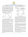
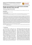
III. TOP LEVEL SYSTEM DESCRIPTION
The top level block diagram as shown in Fig:1
comprises of the central 8051 microcontroller interfaced
with the peripheral devices such as Keyboard, LCD, LED
and Motor driver. A Component Off-The- Self (COTS)
8051 KIT has been used to speed up the prototype
development process. Each of the peripheral devices has
been explained in next page.
380
International Journal of Emerging Technology and Advanced Engineering
Website: www.ijetae.com (ISSN 2250-2459, ISO 9001:2008 Certified Journal, Volume 3, Issue 11, November 2013)
The system is driven by a regulated 5V DC, 1A power
supply. The system design has been kept simple so as to
realize a less expensive miniature portable lab prototype
model. The 4x4 keypad has been used to key in the desired
motor speed. The LCD displays the desired speed and the
actual speed of the motor. There are three LEDs of Red,
Blue and green colour to indicate the comparator outputs
status i.e. Equal, Greater and Lesser. The motor driver is an
additional attachment designed in the Lab with just enough
current driving capability to drive a 6V DC toy motor.
Higher the PWM duty cycle higher the voltage across
the DC motor, thus increasing the motor speed.
Fig:2 Closed Loop Control System
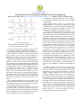
Fig: 3 shows the PWM signal with different duty cycles.
The motor speed is encoded using a slotted wheel mounted
on the shaft of the motor as shown in Fig:7. The IR
transmitter and receiver mounted on both sides of the wheel
registers the absence and presence of the slots when the
slotted wheel mounted on the motor shaft is rotating. The
IR receiver generates pulse signal at the rate of the motor
speed. In the present design the motor wheel has 8 slots,
thus 8 pulses are generated per one rotation of the wheel.
The speed feedback sampler counts the motor encoder
pulses at every one sec. The speed feedback is passed to the
error comparator.
Dc Motor: DC motors are widely used because
controlling a DC motor is somewhat easier than other kinds
of motors. When DC voltage is applied with proper current
to a motor, it rotates in a particular direction but when the
connection of voltage between two terminals is reversed,
motor rotates in another direction. In present design a 6V
DC toy motor is used.
Pulse Width Modulation (pwm): The Pulse-WidthModulation (PWM) in microcontroller is used to control
duty cycle of DC motor. PWM is an entirely different
approach to controlling the speed of a DC motor. Power is
supplied to the motor in square wave of constant voltage
but varying pulse-width or duty cycle.
Since the frequency is held constant while the on-off
time is varied, the duty cycle of PWM is determined by the
pulse width. The expression of duty cycle is determined by,
Duty cycle = (ON/ON+OFF)*100.
Fig:1 System Level Block Diagram
Motor driver module has been designed as a detachable
entity so that it can be used in another motor control system
for example FPGA based motor control system. Three
signals namely PWM, motor speed encoder pulse and a
ground are used to connect between the 8051 KIT and the
motor drive control unit. Separate 6V DC supply is
provided to the motor driver unit.
The 8051 KIT connected to keyboard and LCD without
the motor driver unit can be used for other applications
based lab experiments such as simple calculator etc.
The closed loop control system is shown in Fig- 2. The
desired speed set by the user is compared against the
feedback speed. The feedback is sampled at every 1 sec
interval. However this sampling interval can be changed to
see the effect of the closed loop response. The error
comparator generates three signals i.e. Greater, Equal,
Lesser when the set speed > actual speed, set speed =
actual speed, set speed < actual speed respectively. These
three signals in turn controls the following up/down
counter. Positive error increments the counter, negative
error decrements the counter, and at no error counter value
is not changed. The counter output is passed to the next
block which generates the PWM signal. The PWM duty
cycle is proportional to the counter value. So, a positive
error increments the count, which in turn increments the
PWM duty cycle.
381
International Journal of Emerging Technology and Advanced Engineering
Website: www.ijetae.com (ISSN 2250-2459, ISO 9001:2008 Certified Journal, Volume 3, Issue 11, November 2013)
In addition to these physical devices, several companies
also offer MCS-51 derivatives as IP cores for use in FPGA
or ASIC designs.
Intel's original MCS-51 family was developed using
NMOS technology, but later versions, identified by a letter
C in their name (e.g., 80C51) used CMOS technology and
consume less power than their NMOS predecessors. This
made them more suitable for battery-powered devices.
LCD: The LCD Module can easily be used with an 8051
microcontroller. The LCD requires 3 control lines and 8 I/O
lines for the data bus. The three control lines are referred to
as EN, RS, and RW. The EN line is called "Enable." To
send data to the LCD, this line is first made low (0) and then
the other two control lines are set and data is put on the data
bus. When the other lines are completely ready, EN is made
high (1) for the minimum amount of time required by the
LCD datasheet (this varies from LCD to LCD), and end by
bringing it low (0) again. The RS line is the "Register
Select" line. When RS is low (0), the data is to be treated as
a command or special instruction (such as clear screen,
position cursor, etc.). When RS is high (1), the data being
sent is text data which should be displayed on the screen.
For example, to display the letter "T" on the screen you
would set RS high. The RW line is the "Read/Write" control
line. When RW is low (0), the information on the data bus is
being written to the LCD. When RW is high (1), the
program is effectively querying (or reading) the LCD. Only
one instruction ("Get LCD status") is a read command. All
others are write commands--so RW will almost always be
low.
KEYPAD: Keypads are often used as a primary input
device for embedded microcontrollers. The keypads actually
consist of a number of switches, connected in a row/column
arrangement. In order for the microcontroller to scan the
keypad, it outputs a nibble to force one (only one) of the
columns low and then reads the rows to see if any buttons in
that column have been pressed. The rows are pulled up by
the internal weak pull-ups in the 8051 ports. Consequently,
as long as no buttons are pressed, the microcontroller sees
logic high on each of the pins attached to the keypad rows.
The nibble driven onto the columns always contains only a
single 0. The only way the microcontroller can find a 0 on
any row pin is for the keypad button to be pressed that
connects the column set to 0 to a row. The controller knows
which column is at a 0-level and which row reads 0,
allowing it to determine which key is pressed.
FIG:3 Duty Cycle Calculation
The speed of the motor depends on three factors:
(a) Load (b) Voltage and (c) Current.
For a given fixed load we can maintain a steady speed by
using a method called pulse width modulation (PWM).
By changing (modulating) the width of the pulse applied
to the DC motor we can increase or decrease the amount of
power provided to the motor, thereby increasing or
decreasing the motor speed. Notice that, although the
voltage has fixed amplitude, it has a variable duty cycle.
That means the wider the pulse, the higher the speed.
PWM is so widely used in DC motor control that some
microcontrollers come with the PWM circuitry embedded in
the chip. In such microcontrollers the configuration registers
are loaded with the values of the high and low portions of
the desired pulse, and the rest is taken care by the
microcontroller. This allows the microcontroller to do other
things. For microcontrollers without PWM circuitry, the
various duty cycles pulses are generated using software,
which prevents the microcontroller from doing other things.
The ability to control the speed of the DC motor using
PWM is one reason that DC motors are preferable over AC
motors.
8051 MICROCONTROLLER: The microcontroller acts
like the brain of the DC motor speed control system. The
microcontroller chip that has been selected for the purpose
of controlling the speed of DC motor is 8051.
The Intel MCS-51 (commonly referred to as 8051) is
Harvard architecture, single chip microcontroller (µC) series
which was developed by Intel in 1980 for use in embedded
systems. While Intel no longer manufactures the MCS-51,
binary compatible derivatives remain popular today.
382
International Journal of Emerging Technology and Advanced Engineering
Website: www.ijetae.com (ISSN 2250-2459, ISO 9001:2008 Certified Journal, Volume 3, Issue 11, November 2013)
IV. DESIGN & SIMULATION
Model based design approach is an ideal approach for
Embedded System Design. There are many system model
tools available from various vendors. These tools facilitate
the design of hardware and software before actual physical
implementation of the system. Proteus tool is used for this
project. The Protues tool also provides virtual instruments
like Oscilloscope, Logic analyser to monitor the signals of
the system. Students install and learn the use of the Proteus
tool by going through the readymade examples which
comes free with the tool. Step by step design process of
building a small system for example flashing, counting,
shifting, and rotating a set of LEDs connected to 8051
Microcontroller ports is designed and practiced using the
assembly language programming and drawing the schematic
of the system. Proteus allows assembly code to be
assembled and downloaded on the virtual 8051. For C
language coding Keil compiler can be used and the
generated hex code can be used to configure and run the
virtual 8051.
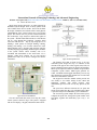
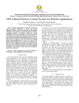
Fig:5 Closed Loop Flow Chart
The firmware flow chart is shown in Fig- 5. In every
embedded system design first step is to initialize all the
elements in the project. Here LCD, keypad, timer, LED, ref
speed is initialized. Device driver for Keypad, LCD display,
Motor speed sampler and firmware modules for Speed Error
comparator, Up/Dn counter, PWM signal generator are
coded, assembled and debugged individually. In next step
these modules are integrated for uniform flow of control and
data across all modules in real time.
The keypad User Interface Module (UIM) provides the
user facility to view and/or change all the control and
monitoring variables with control program. After
initializations processor waits for any key pressed by the
user.
The speed error difference between the set speed and
actual speed controls the duty cycle of PWM signal. If there
is speed error the previous PWM duty cycle is maintained.
The closed loop system samples the motor actual speed,
computes the speed error, changes the Up/Dn counter value
and finally regulates the PWM duty cycle every 1 sec
interval.
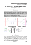
Fig:4 Proteus Circuit Simulation
The 8051 microcontroller based closed loop DC motor
control system as shown in Fig-4. The system is equipped
with an LCD display, a keypad, transistorized motor driver.
383
International Journal of Emerging Technology and Advanced Engineering
Website: www.ijetae.com (ISSN 2250-2459, ISO 9001:2008 Certified Journal, Volume 3, Issue 11, November 2013)
Fig:6 Hardware Setup
The hardware development setup is shown in Fig-6. The
8051 KIT is procured from a local vendor. The Motor driver
unit is assembled using the motor, gear and wheel
arrangement available in a bought out Toy Mechano KIT.
The 8051 KIT and the motor driver unit as shown in the
figure are driven by an external +5V Lab power supply. The
micro controller is programmed by the Topwin programmer
before mounting on the 8051 socket of the KIT. Two
important signals i.e. PWM from microcontroller KIT to
motor driver unit and motor speed encoder clock from the
motor driver unit to microcontroller KIT, and common
ground signal are wired between the two units. The motor
driver unit has a 9 pin D connector through which all the
signals are brought out.
The motor driver as shown in Fig-7 is a Darlington
transistor comprising of a switching transistor BC 457 and
power transistor SL100 to drive sufficient current to rotate
the motor. When the low power switching transistor BC-457
is OFF the high power transistor SL-100 is ON and them
motor gets supply current and rotates. Hence the PWM
pulse needs to be reversed so that ON period of PWM
decides the motor ON period. The average voltage decides
speed of the motor. The IR LED based speed encoder
generates pulses in proportion to the rotation of the motor.
The speed encoder is made out of a wheel with 8 holes. So
the IR transmitter/receiver LED generates 8 pulses per one
revolution of the motor.
Fig:7 Motor Driver Diagram
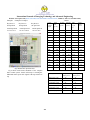
II. TESTING & OBSERVATION
The motor control system is tested in both open loop and
closed loop. Table-1 shows the PWM duty cycle and the
speed of rotation of the motor in open loop without the
speed feedback. As seen the motor fails to start at low ON
period since the average voltage across motor is not
sufficient to overcome the stall inertia. Table – 2 shows
observation during closed loop system. The numeral 1 to 9
is keyed in, which represents 10% to 90% duty cycle
respectively. The next column shows the actual speed
closely following the desired speed which confirms the
closed loop operation of the motor. Initially the motor
rotates from stall condition and the actual speed gradually
increases and matches the desired speed. While the motor is
picking up speed the three Red, Green and Blue LED
displays the relational difference between the desired speed
and actual speed as given in following examples.
Design Simulation
Let SET SPEED=A and ACTUAL SPEED=B
If A>B then RED LED will glow.
If A<B then GREEN LED will glow.
If A=B then BLUE LED will glow.
384
International Journal of Emerging Technology and Advanced Engineering
Website: www.ijetae.com (ISSN 2250-2459, ISO 9001:2008 Certified Journal, Volume 3, Issue 11, November 2013)
Example.1
Example.2 Example.3
TABLE I
Key Press=8
Key Press=8
Key Press=8
Up/Dn
Set Speed=44
Set Speed=44
Set Speed=44
Counter
Output
Actual Speed=44
Actual Speed=45
Actual Speed=41
LED Glow=BLUE
LED Glow=GREEN
LED Glow=RED
Total
time
On time
Off time
Duty
(µ sec)
(µ sec)
Cycle
(µ sec)
Speed
Pulses
per sec
%
0000
160
10
150
6.250
-
0001
160
20
140
12.50
-
0010
160
30
130
18.75
-
0011
160
40
120
25.00
-
0100
160
50
110
31.25
-
0101
160
60
100
37.50
12
0110
160
70
90
43.75
16
0111
160
80
80
50.00
24
1000
160
90
70
56.25
28
1001
160
100
60
62.50
34
1010
160
110
50
68.75
40
1011
160
120
40
75.00
44
1100
160
130
30
81.25
50
1101
160
140
20
87.50
54
1110
160
150
10
93.75
56
1111
160
150
10
93.85
56
Fig:8 PWM & Motor Speed Waveform
TABLE III
Fig.8 shows model based simulation of the complete
motor control system. Virtual oscilloscope is showing the
PWM and motor speed clock signals at the top and next to
top.
Key Press
385
Set Speed
Actual Speed
clocks per sec
clocks per sec
9(90% duty cycle)
56
55
8 (80% duty cycle)
48
47
7 (70% duty cycle)
42
41
6 (60% duty cycle)
34
33
5 (50% duty cycle)
30
29
4 (40% duty cycle)
24
23
International Journal of Emerging Technology and Advanced Engineering
Website: www.ijetae.com (ISSN 2250-2459, ISO 9001:2008 Certified Journal, Volume 3, Issue 11, November 2013)
[2]
V. CONCLUSION & FUTURE SCOPE
The design of a closed loop system to control the speed
of a DC Motor was successfully implemented in this paper.
DC motors have speed control capabilities which means that
speed, torque and even direction of rotation can be changed
at any time to meet new condition. The hardware of the
proposed system and interfacing with computer is explained
in this paper .The case study satisfied the objective of
learning 8051 microcontroller in a practical way.
The paper can be redesigned on AVR and ARM
microcontroller platforms. The scope of the project can be
further extended by inclusion of a PID controller in control
system taking into account motor electrical time constant.
[6]
[7]
MCS-51TM Macro Assembler User's Guide, Publication number
9800937, Intel Corporation.
Prof. shashank pujari, ―A simple closed loop dc motor speed control
system on fpga platform for vhdl beginner‖, International Journal of
Scientific & Engineering Research Volume 4, Issue3, March-2013
Jimenez-Fernandez, A. ; Arquitectura y Tecnol. de Computadore,
Univ. de Sevilla, Sevilla ; Paz-Vicente, R. ; Rivas, M. ; LinaresBarranco, A.,‖ AER-based robotic closed-loop control system‖,
ISCAS 2008.
Beetner, d. ; dept. of electr. & comput. eng., missouri univ., rolla,
mo, usa ; pottinger, h. ; mitchell, k. ―Laboratories teaching concepts
in microcontrollers and hardware-software co-design‖, frontiers in
education conference, 2000. fie 2000. 30th annual (volume:2 )
Mazidi & mazidi ―The 8051 Microcontroller Embedded Systems‖.
Proteus & Keil user manual.
[8]
Guoshing Huang ,Shuocheng Lee‖PC-based PID speed control
[3]
[4]
[5]
Acknowledgment
in DC motor‖
Authors wish to thank Sambalpur University Institute Of
Information Technology for the support in providing the
development tools, KITs and laboratory infrastructure in
carrying out this project.
[9]
waveforms from the DC-link current of an inverter‖, : IEE
Proceedings B (Electric Power Applications), Volume 136,
Issue 4, July 1989, p. 196 – 204
REFERENCES
[1]
T.C. Green 1 ; B.W. Williams ―Derivation of motor line-current
John Wharton: An Introduction to the Intel MCS-51TM Single-Chip
Microcomputer Family, Application Note AP-69, May 1980, Intel
Corporation.
386