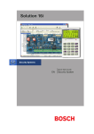
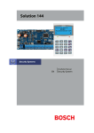
Download Bosch Solution 16Plus
Transcript
Solution 16 plus ���������������� EN Quick Start Guide Security System Solution 16plus Quick Start Guide Co py r i ght Notice Te l e p e r m i t N o te Unless otherwise indicated, this publication is the copyright of Bosch Security Systems Pty Ltd (“Bosch”). All rights are reserved.You may download a single copy of this publication. By downloading the publication you agree that you will: (i) only use the publication for your own reference; (ii) not commercially exploit or charge any person for the use of the publication; and (iii) not modify the publication in any way without the prior written permission of Bosch. Except as specified above or where authorised by the Copyright Act 1968 (Cth), no part of this publication may be reproduced, transmitted, modified or stored in any form or by any means, without the prior written permission of Bosch. The grant of a Telepermit for a device in no way indicates Telecom acceptance of responsibility for the correct operation of that device under all operating conditions. Tra d e m arks Throughout this document trademark names may have been used. Rather than put a trademark symbol in every occurrence of a trademark name, we state that we are using the names only in an editorial fashion and to the benefit of the trademark owner with no intention of infringement of the trademark. N o t i ce of Liabilit y While every effort has been taken the accuracy of this document, neither Bosch Security Systems Pty Ltd nor any of its official representatives shall have any liability to any person or entity with respect to any liability, loss or damage caused or alleged to be caused directly or indirectly by the information contained in this book. Should you find any error on inconsistency, please notify us accordingly. This equipment shall not be used in any manner that could constitute a nuisance to other Telecom customers. Immediately disconnect this equipment should it become physically damaged, and arrange for its disposal or repair. The transmit level from this device is set as a fixed level and because of this there may be circumstances where the performance is less than optimal. Before reporting such occurrences as faults, please check the line with a standard telepermitted telephone. Warnings 1) This product must be installed by a qualified and licensed security installer. 2) This product may not perform as expected if installed incorrectly. 3) Some features of this product require a working telephone line to operate and telephone communication service provider charges are applicable. 4) Australian standard AS 2201 requires regular service by qualified and licensed security persons and regular user testing. Please consult your security alarm company for further details. 5) Incorrect programming of parameters can result in operation contrary to what may be desired. 6) Leave the mains adapter plugged in at all times. 7) Leave the telephone line plugged in at all times under normal conditions. Bosch Security Systems Pty Ltd reserves the right to make changes to features and specifications at any time without prior notification in the interest of ongoing product development and improvement. 2 Bosch Security Systems 09/06 BLCC100R Solution 16plus Quick Start Guide CONTENTS Copyright Notice .................................................................................. 2 Trademarks ............................................................................................. 2 Notice of Liability.................................................................................. 2 Telepermit Note .................................................................................... 2 FEATURES ................................................................................4 OVERVIEW ...............................................................................4 ABOUT THE PANEL ..................................................................5 Mounting The CABINET ...................................................................... 5 Module Spaces ...................................................................................... 5 PANEL LED Indicators .......................................................................... 5 Panel Address Select ........................................................................... 5 WIRING DIAGRAMS ................................................................6 EOL Resistor Colour Code (4 Band) ................................................ 6 Terminal Descriptions ......................................................................... 9 Board Connectors................................................................................. 9 ABOUT THE KEYPAD ............................................................... 9 Keypad Key Functions ........................................................................ 9 Keypad Setup .......................................................................................10 Keypad Address Select .....................................................................10 Status Icons / LED’s ............................................................................11 Keypad Tones .......................................................................................11 PROGRAMMING OVERVIEW ................................................12 Entering Programming Mode ........................................................12 Exiting Programming Mode ...........................................................12 Navigating The Menu........................................................................12 Command Menu .................................................................................12 Programming Option Bit Menus ...................................................12 Alpha Text..............................................................................................12 Telephone Numbers ..........................................................................13 List Options ...........................................................................................13 Clock Programming ...........................................................................13 GETTING STARTED BACK TO BASE ......................................13 SERVICE MODE ......................................................................13 DEFAULTING THE SYSTEM ...................................................14 DOMESTIC TEMPLATE DEFAULTS ........................................14 DIRECT LINK PROGRAMMING .............................................14 ZONE ARRAY ..........................................................................14 BASIC REPORTING REFERENCE ...........................................14 MENU REFERENCE TABLE .....................................................15 PROGRAM LOCATIONS .........................................................18 Access Programming ........................................................................18 User Default Table ..............................................................................18 Area Programming.............................................................................19 Input Programming ...........................................................................21 Zone Default Table .............................................................................22 Output Programming .......................................................................23 Output Default Table .........................................................................23 One Shot Mode ...................................................................................24 Pulsing Mode .......................................................................................24 Output Event Types ...........................................................................24 Comms Programming ......................................................................25 Device Programming ........................................................................28 System Programming .......................................................................30 TESTING THE SYSTEM...........................................................32 SPECIFICATIONS ...................................................................33 Bosch Security Systems 09/06 BLCC100R FIGURES Figure 1 : Cabinet Dimensions ........................................................ 5 Figure 2: Metal Box – Module Space Allocations ...................... 5 Figure 3: N/C No EOL Zone................................................................ 6 Figure 4: N/C Single EOL Zone ......................................................... 6 Figure 5: N/C Split EOL Zone ............................................................ 6 Figure 6: N/C Zone With Tamper ..................................................... 6 Figure 7: N/O No EOL Zone ............................................................... 6 Figure 8: N/O Single EOL Zone ........................................................ 6 Figure 9: N/O Split EOL Zone ............................................................ 6 Figure 10: N/O Zone With Tamper .................................................. 6 Figure 11: EOL Resistor Colour Chart............................................. 6 Figure 12: Solution 16plus Board Layout ........................................ 7 Figure 13: Solution 16plus Connection Diagram ......................... 8 Figure 14: Keypad DIP Switch Address Settings ......................10 Figure 15: Sample Option Bit Menu Display .............................12 Figure 16: Area Text Programming Display ...............................12 Figure 17: Telephone Number Programming Display ...........13 Figure 18: List Option Programming Display ...........................13 Figure 19: Clock Programming Display ......................................13 Figure 20: Sample Zone Array Display ........................................14 TABLES Table 1: Dialler LED Meanings .......................................................... 5 Table 2: Status LED Meanings .......................................................... 5 Table 3: Panel Node Select ................................................................ 5 Table 4: Terminal Block Descriptions ............................................. 9 Table 5: Board Connector Descriptions ........................................ 9 Table 6: Keypad DIP Switch Address Settings ..........................10 Table 7: Keys Used During Programming ..................................12 Table 8: Text Keypad Character Set ..............................................12 Table 9: Phone Number Character Set ........................................13 Table 10: Domestic Keypad DIP Switch Address Settings....14 Table 11: Basic Reporting Code Reference Listing .................14 Table 12: Menu Structure And Layout ........................................17 Table 13: User Default Programming Options .........................18 Table 14: Zone Types .........................................................................21 Table 15: Zone Defaults ....................................................................22 Table 16: Output Default Table ......................................................23 Table 17: Output Polarity Types .....................................................24 Table 18: Output Event Types.........................................................24 3 Solution 16plus Quick Start Guide Fe at u re s O ve r v i e w Listed below are the main features of the Solution 16plus Control Panel. Zones The Solution 16plus control panel provides up to 16 separate zones of protection. Zone programming determines the panel’s response to open/short and tamper conditions on the zone loop. Individual Box Tamper Circuit Monitoring Report Via Email (Internet) Telephone Line Busy Tone Detect RAS Intelli-connect® CLI Caller Line Identification Daylight Savings Senior Watch System Maintenance Interval Reminder System Weekly Test Reminder Area Inactivity Interval Temporary Pin Code Dual Reporting Dual Redundant Reporting Alarm Report Abort/cancel Options 8 Programmable Holiday Calendars 8 Programmable Schedules 16 fully programmable Zones Fire Alarm Verification 48 Pin Codes 3 Supervised High Power Digital Outputs 1 Relay 2 Amp Form (C) Contact (Expandable to 13) Supervised Siren Driver Partitionable To 8 Areas Dialler Reports SIA, Contact ID, SMS and Email Formats Supervised LAN Keypads (Maximum 8 Keypads) Keyswitch Input 256 History Event Memory EMI / Lightning Transient Protection Fully Menu Text Programmable Areas The control panel supports up to 4 separate areas. You can assign all zones to a single area, or you can assign each zone to a combination of different areas. You can arm and disarm the control panel by area, alternatively, you can arm and disarm several areas at the same time. Dialler The control panel has a built-in dialler to send reports to the receiving party (ie. Security company monitoring station, mobile phone etc). Keypads You can connect a maximum of 8 fully supervised keypads to the control panel. The available current affects the total number of keypads that you can connect without the need to provide additional power supplies. History Log The control panel can store up to 256 history events from all 8 areas. All events are stored in the log, even if they are programmed not to report via the on-board dialler. You can view the control panel’s history log via keypad, serial printer (optional), or by connection of a personal computer (direct/remote) using the SolutionLink upload/ download software. Programming You can program the Solution 16plus either by a keypad or using a personal computer using the Solution Link upload/ download software. Programmable Via Solution Link Software (Remote/Direct) Telephone Line Fail Monitor Time Executed Functions 60 Output Event Types Exit Restart Expansion Module Supervision DTMF Tone Decoder Built In Remote Arming 4 Bosch Security Systems 09/06 BLCC100R Solution 16plus Quick Start Guide Ab o u t The Panel M o u nting The Cabinet 257 The cabinet should be mounted via 4 (screws/bolts) through the 4 mounting holes in the base. Ensure that the enclosure is mounted on a solid, flat, vertical surface such that the base will not flex when tightened. Cabinet dimensions are shown below. Figure 2: Metal Box – Module Space Allocations Pa n e l Le d I n d i c ato r s 375 90 The Solution 16plus PCB has two LED indicators (Dialler and Status LED’s) which display the following information. Condition Off On Flashing Figure 1 : Cabinet Dimensions Meaning Offline On Line (Dialling/Answered) Incoming Call Table 1: Dialler LED Meanings M o d u le Spaces Each cabinet has 4 identical module spaces and 1 large module space that is allocated for non Solution PCB boards (eg. a securitel STU). Each space includes 4 x 10mm stand-offs that the optional expander PCB boards will mount using screws (screws will be supplied with each board). The expander board will be earthed via the screws that mount the PCB to the metal box. All modules will mount on these module spaces. A list of the PCB boards is detailed below Module Space Occupied Solution 16plus Control Panel 2 Module Spaces CM104 Zone Expander 1 Module Space CM110 Output Expander 1 Module Space CM120 LAN Power Supply 1 Module Space CM195 RF Receiver Expander 1 Module Space Using the above table, the installer can determine how many modules can be mounted in a single cabinet box. On some export models, module 3 will not be available as the transformer mounts in this location. Condition Off On Flash Once Every 2 Seconds Flash Fast Meaning Error Error OK AC or Battery Trouble Table 2: Status LED Meanings During factory defaulting the Status and Dialler LED indicators will be on steady for approximately Note 15 seconds. i Pa n e l Ad d re s s S e l e c t The Solution 16plus pcb has three DIP switches (called Panel Node Select) that must be set. In a multi-panel system, each control panel (Node) must to be set to a unique address. Panel NODE Select DIP Switch Address Settings Panel to Address Panel 1 Panel 2 Panel 3 Panel 4 Panel 5 Panel 6 Panel 7 Panel 8 S1 Off On Off On Off On Off On S2 Off Off On On Off Off On On S3 Off Off Off Off On On On On Table 3: Panel Node Select The node switch should be left at Panel 1 position for Solution 16plus. OFF-OFF-OFF. On later versions Note this switch may have been omitted. This is not a fault. i Bosch Security Systems 09/06 BLCC100R 5 Solution 16plus Quick Start Guide Wi r i n g Diagrams ���� ���� ��� ZONE 2 N/C ���� ZONE 1 N/O ZONE 2 ��� ZONE 1 N/C N/O 2 ���� Figure 7: N/O No EOL Zone Figure 3: N/C No EOL Zone ALARM N/C ��� N/C ZONE 2 ��� N/C ALARM ���� ZONE 1 ALARM (3K3 EOL) ���� ZONE 9 (6K8 EOL) (6K8 EOL) ZONE 1 ZONE 9 Figure 9: N/O Split EOL Zone TAMPER (6K8 EOL) N/C ZONE 1 (3K3 EOL) ����2 ���� ��� N/C TAMPER TAMPER (6K8 EOL) ALARM TAMPER ALARM ���� N/C (3K3 EOL) N/O ��� Figure 5: N/C Split EOL Zone ��� ALARM ALARM N/O ��� ZONE 2 N/O ���� ALARM ZONE 1 Figure 8: N/O Single EOL Zone Figure 4: N/C Single EOL Zone ����1 N/O ���� ALARM N/C N/O ���� ���� ZONE 1 ���� ALARM ZONE 1 (3K3 EOL) ���� Figure 6: N/C Zone With Tamper Figure 10: N/O Zone With Tamper The Above diagrams display zone configurations using Normally-Closed Alarm contacts and Note Normally-Open Alarm Contacts. When using Normally-Open Alarm Contacts you must select Inverted Seal for each zone in MENU 3-1-8. A shorted loop is a tamper condition for all EOL zone configurations. i E O L R e s i s to r Co l o u r Co d e ( 4 B a n d ) Figure 11: EOL Resistor Colour Chart 6 Bosch Security Systems 09/06 BLCC100R Solution 16plus Quick Start Guide ��������� ������������ ������������� �������������� ���������� ��������� ��������� ������������ ������������ �������� ��������� ����� ��������� ������������� ����������� ����������� �������������������� ����������� ������ �������������������� ���������������������� ������������ ����������������� ���������� ������������ ������ ������������� ������������ ��������������� ���������� ��������������� ������ ������������ ��������� ������������ ����������� ������������ ����� ���������� ��������� ������������� ������������������ ����������� ��������� ������������� ������������� ������������ �������������� ���������� ���������� �������������� ����������������� ����������� Figure 12: Solution 16plus Board Layout Bosch Security Systems 09/06 BLCC100R 7 Solution 16plus Quick Start Guide Connect To Cabinet Tamper 16Vac 22VA Plug Pack GREEN YELLOW YELLOW + 12VDC 7Ah Sealed Lead Acid Battery - + Accessories (e.g. PIR Detectors) - Connect To Zone Terminals NC COM LAN + Keypad / LAN Expansion Device LAN LAN A LAN B Relay Output COM Terminal -/+ Select PINS Siren Tamper Switch Horn Speaker N/C Strobe Light + Piezo Siren - Smoke Detector - + - + NOTE: For Piezo Siren Operation Short Relay Select PINS COM and GND RF DATA N/C ZONE 5 N/C ZONE 6 DIGIFLEX N/C VISION N/C Security Controller ZONE 8 N/C ���������� ZONE 7 PORT ZONE 4 SERIAL N/C N12138 ZONE 3 N12138 N/C ON +12V GND ZONE 2 1 2 3 Connect To Accessory Power N/C Refer To Documentation For DIALER & STATUS LED’s RF Receiver ZONE 1 Incoming Street Telephone Line Premises Telephone Connect To Telephone Line Mode 3 RJ12 6P4C To RJ12 6P4C Telephone Lead Figure 13: Solution 16plus Connection Diagram 8 Bosch Security Systems 09/06 BLCC100R Solution 16plus Quick Start Guide Te r m i nal Descriptions Nº Name 1 Earth 2 3 ~ (AC) ~ (AC) Connection of the A.C. plug pack transformer 4 5 BAT (-) BAT (+) Negative and positive connections to the stand-by battery. 12 VDC / 7AH 6 7 8 9 10 11 +12 V +12 V +12 V GND GND GND These terminals are used to power detectors and LAN devices up to 750 mA. 12 13 LAN + LAN - These terminals are used to power LAN devices up to 750 mA. LAN A Connect the LAN A data terminal of any LAN device (eg. Keypads, expansion boards) to this terminal. The control panel supports up to 300 m of 24/0.20 (18 AWG) wire on these terminals. 14 15 LAN B Description Earth wire from this terminal is connected to the Mains earth. Connect the LAN B data terminal of any LAN device (eg. Keypads, expansion boards) to this terminal. The control panel supports up to 300 m of 24/0.20 (18 AWG) wire on these terminals. Alarm power capable of providing a 16 COMM+ maximum of 2 Amp (+). This terminal is PTC Fuse protected. Nº 32 Name ZN 6 Description Zone 6 and 14 sensor loop input (+). 33 ZN 7 Zone 7 and 15 sensor loop input (+). 34 GND Common (-) for Zone 7 and 8 sensor loop. 35 ZN 8 Zone 8 and 16 sensor loop input (+). 36 37 IN IN These terminals are used to connect the telephone line from the street. 38 39 OUT OUT These terminals are used to connect the premises telephones. Table 4: Terminal Block Descriptions B o a rd Co n n e c to r s Connector Description This socket allow you to connect a service Service Keypad to the panel during installation. Tamper This socket is used to connect the panel enclosure tamper switch. Default This push button is used to reset the control panel back to factory default. Voice Module This is used to connect the optional Voice Command Module (CM100). Serial This socket is used to connect serial devices to the control system like the direct link programming module. Telco This is a RJ12 6P/4C connector that allows you to connect the control panel to the PSTN telephone line. Relay The relay select PIN’s allow you to easily program the relay common contact to switch either +12v or GND by fitting a plug on link. 17 18 19 OUT 1 OUT 2 OUT 3 Programmable output, capable of providing a maximum of 500 mA (-). This terminal is PTC Fuse protected. 20 21 22 N/C COM N/O 2 A @ 24 VDC Relay Output Form C contact 23 INPUT Programmable Input for RF Receivers, Keyswitch and other devices. 24 ZN 1 Zone 1 and 9 sensor loop input (+). 25 GND Common (-) for Zone 1 and 2 sensor loop. 26 ZN 2 Zone 2 and 10 sensor loop input (+). 27 ZN 3 Zone 3 and 11 sensor loop input (+). 28 GND Common (-) for Zone 3 and 4 sensor loop. 29 ZN 4 Zone 4 and 12 sensor loop input (+). Key Description 30 ZN 5 Zone 5 and 13 sensor loop input (+). to 31 GND Common (-) for Zone 5 and 6 sensor loop. The numeric keys allow you to enter you numbers when required Bosch Security Systems 09/06 BLCC100R Table 5: Board Connector Descriptions Ab o u t Th e Ke y p a d The Graphic Keypad has 20 keys or buttons. The buttons allow you to input instructions and navigate the menu screens as required. Some buttons have a secondary function which is activated by holding them down for two seconds. Each button’s function is described below Ke y p a d Ke y Fu n c t i o n s Use the [MENU] and the numeric keys to enter commands. The [MENU] key is also used to go back one level when navigating through menus or to exit a programming location without saving changes. 9 Solution 16plus Quick Start Guide Key Description The [ON] key allows you to turn an area or output on. To turn all areas on at the same time when the system has been partitioned, press and hold the [ON] key for two seconds. The [PART] key allows you to turn an area Part On. This key can also be used to bypass a zone or multiple zones when you press and hold for two seconds. The [OFF] key allows you to turn an area or output off. To turn all areas off at the same time when the system had been partitioned, press and hold the [OFF] key for two seconds. The [OK] key allows you to save any changes and exit the command. The [MAIL] key allows you to read stored mail. This key can also be used to initiate a dialler test when you press and hold for two seconds. The [] key allows you to move the cursor left when programming text or telephone numbers. The [] key allows you to move the cursor right when programming text or telephone numbers. Key Description + for 2 sec Pressing the 7 and 9 keys together and holding them down for 2 seconds will cause a Medical alarm to be triggered. If programmed the sirens will sound and the monitoring station will be notified. Ke y p a d S e t u p The Solution 16plus control panel can have a maximum of 8 keypads connected via the LAN terminals. Each keypad must be set to a unique address before they will operate. Each keypad needs to be assigned to a home area via MENU 6-1-3. This sets the area the keypad will display and control by default. Keypads can be locked to a home area or allowed to roam or move between areas. When the system is powered up, any keypads which have not been assigned a home area will be automatically set to home area 1. Set each keypad address using the table below as a guide. Only 1 Keypad can be assigned to each address. All Keypads are supplied from the factory set to address Note 1. (OFF-OFF-OFF). i Ke y p a d Ad d re s s S e l e c t The [↑] key allows you to navigate through menus or to toggle characters when programming telephone numbers. The [] key allows you to navigate through menus or to toggle characters when programming telephone numbers. Pressing The [] key will display current trouble conditions when the area that the keypad is displaying is disarmed. + for 2 sec + for 2 sec Pressing the 1 and 3 keys together and holding them down for 2 seconds will cause a Panic alarm to be triggered. If programmed the sirens will sound and the monitoring station will be notified. Pressing the 4 and 6 keys together and holding them down for 2 seconds will cause a Fire alarm to be triggered. If programmed the sirens will sound and the monitoring station will be notified. Figure 14: Keypad DIP Switch Address Settings Keypad DIP Switch Address Settings Keypad To Address S1 S2 S3 Keypad 1 Off Off Off Keypad 2 On Off Off Keypad 3 Off On Off Keypad 4 On On Off Keypad 5 Off Off On Keypad 6 On Off On Keypad 7 Off On On Keypad 8 On On On Table 6: Keypad DIP Switch Address Settings 10 Bosch Security Systems 09/06 BLCC100R Solution 16plus Quick Start Guide St at u s Icons / LED ’s The following table lists the function of each of the ICON Symbols and LED Indicators on the Graphic Keypad Display. Icon Status Meaning The keypad can display which areas (1 – 8) are turned on or off via the Area Icon Indicators. This programmable option can be disabled in MENU On The area is turned All On or Part On Off The area is turned Off Flashing Fast The area has an alarm On System power is normal Flashing System power is missing Flashing A fire alarm is active Off No fire alarm On Fire alarm in memory (Turn the area All On and Off to Clear). On The existing service or trouble condition has been acknowledged. Off No service or trouble conditions exist Flashing A service or trouble condition is present that has not been acknowledged. On The area is turned Part On. Off The area is not turned Part On. On The area is turned off. Off The area is turned All On or Part On On The area is turned All On Off The area is turned Off On You have mail waiting to be read Off No Mail On Area is ready to turn on (All On / Part On) Off Not ready, Zone Open Bosch Security Systems 09/06 BLCC100R Red LED Green LED Red & Green LED On All On Flashing Alarm On Area is off. Flashing Area not ready to turn on Flashing Installer programming mode is active. Ke y p a d To n e s All keypads emit several distinct tones and display text to alert you to system events. The volume of the keypad tones can be adjusted in MENU 6-1-0. Type Meaning Fire Alarm Tone When a fire zone sounds an alarm, the keypad will sound 3 seconds on and 2 seconds off (repeat). Burglary Alarm Tone When a burglary zone activates while your system is turned on, your keypad emits a continuous siren tone. It sounds for the time set by your security company. Trouble Tone When a system component is not functioning properly, your keypad sounds 4 fast short beeps followed by a 5 second pause (repeat). Pressing any key on the keypad sounds one Key Press short beep, indicating that the key press is Tone accepted. Entry Delay Tone When you enter the premises through a zone programmed for entry delay, the keypad sound a Hi/Low tone to remind you to turn off the area. If the area is not turned off before the entry delay expires, an alarm condition will sound and a report may be sent to your alarm company. Exit Delay Tone After you turn an area All On, the keypad will sound 1 short beep every second. During the last 10 seconds fast short beeps will be heard. If you don’t exit before the delay time expires and an exit delay door is faulted, an alarm occurs. Error Tone If you press an incorrect key, your keypad will sound a 2 second tone. Menu Mode The keypad will sound a Hi / Lo tone to indicate you have entered MENU Mode and a Lo/Hi tone to indicate you have exited MENU mode. Chime Tone The keypad sounds fast short beeps to alert you when a zone programmed for chime is faulted or unsealled. 11 Solution 16plus Quick Start Guide Pro gra mming O ver view The Solution 16plus Control System incorporates a menu text driven interface. This interface is very similar to that found on many mobile phones. Once programming mode is entered you will see a number of menu options in the display and these may vary depending in the user authority level. E nte r i n g Programming M ode “Move To An Area” or “Turn An Area On”. Use the up and down arrow keys to navigate and press [OK] to select the command. Pro gra m m i n g O p t i o n B i t M e n u s Use the up and down arrow keys to scroll through the 8 different options. To select an option, press the [ON] key – a tick [] will be displayed. To deselect an option, press the [OFF] key. To enter installer program mode enter, PIN + [MENU]. Off On Low Battery Show Overload Report Overload Press OK ON OFF MENU The default Installer PIN is 1234. The Red and Green LED indicators on the keypad will flash to confirm Installer programming mode is active. All areas must be disarmed with no active alarms. To disarm all areas enter the Installer PIN and hold Note the [OFF] Key for 2 seconds. i E x i t i n g Programming M ode Press and hold down [MENU] key for 2 seconds. i You can also select Exit and press [OK] from each menu level. Figure 15: Sample Option Bit Menu Display To save programming changes, press [OK], else press [MENU] to exit without saving. Al p h a Tex t Text descriptions are available for Area Name, Zone Name, User Name, Schedule Name, Holiday Name Prox Reader Name and Output Name. Each name can have a maximum of 16 characters. Area 2 Name Note Reception Area PRESS ◄►, OK or MENU N av i g ating The M enu Using the up and down arrow keys to navigate, locate the desired menu item using the highlight bar and then press the [OK] key to select. A new list of menu items will appear. Repeat the above until the desired menu item is located. To navigate backwards through the menu items press the [MENU] key at any time. Alternatively if you know the direct menu item number press [MENU] + Item Number. Key Description Scrolls Cursor Left Scrolls Cursor Right Scrolls Cursor Up Scrolls Cursor Down OK Enter Menu Options or Saves Changes MENU Go Back One Level, Hold Down to Exit Programming Mode 0 to 9 Enter Data Value ON Turn On Bit Option OFF Turn Off Bit Option, Clear to End of Line Table 7: Keys Used During Programming Figure 16: Area Text Programming Display When programming text, each numeric key represents a different group of characters. Pressing the same numeric key repeatedly will step you through the available characters assigned to the key. The text key layout is the same as most phones. Refer to the table below for detailed character information. Key 1 2 3 4 5 6 7 8 9 0 OFF Characters Assigned To Each Numeric Key . , ? ! & ` 1 A B C a b c 2 D E F d e f 3 G H I g h i 4 J K L j k l 5 M N O m n o 6 P Q R S p q r s 7 T U V t u v 8 W X Y Z w x y z 9 SPACE 0 Scroll Up through entire character list Scroll Down through entire character list Move to left one character position Move to right one character position Clear from cursor postiion to end of line Table 8: Text Keypad Character Set Co m m a nd M enu When you first enter programming mode a special menu called the Command Menu will appear at the top of the menu tree. The Command Menu provides a list of the most common system funtions like “Turn Chime Mode On”, 12 Once the desired character is displayed press the right arrow key to move to the next character position. To save programming changes, press [OK], else press Bosch Security Systems 09/06 BLCC100R Solution 16plus Quick Start Guide [MENU] to exit without saving. G e t t i n g St a r te d B a c k To B a s e The following additional special characters are available by scrolling using the up and down arrow Note keys. + - @ # $ “ & % * : ( ) / < > = i Te l e p hone Numb ers To program, select primary telephone number under [MENU] 5-1-1 then enter the digits of the telephone number and press the [OK] key to save. Use the up and down arrow keys to program special characters (, # and Pause). PRIMARY DEST 1 P001 0297417000 PRESS 0-9 OK to SAVE Figure 17: Telephone Number Programming Display The following steps are the mimimum requirements to get the system reporting back to base. Examples assume the panel is disarmed with no alarms and starting from factory default settings. 1) Enter Program mode. [1234 + MENU] 2) Set Time and Date. [MENU 7-1-0] 3) Change Default Installer PIN. [MENU 1-5-2] 4) Change Default Master Code PIN. [MENU 1-1-1] 5) Enter Account (client) Number, Area 1. [MENU 2-2-0] 6) Key 0 to 9 Characters Assigned To Each Numeric Key Enter the Digits 0 to 9 Enter Base Primary Telephone Number. [MENU 5-1-1] 7) Scroll Up through entire character list 0 - 9 • # , comma = 2 second pause Enter Base Secondary Telephone Number. [MENU 5-1-2] 8) Hold Down MENU To Exit. Move to left or right one character position S e r v i ce M o d e OFF Clear from cursor postiion to end of line Service mode when activated disables dialler reporting, prevents all alarms and prevents all users from arming the system. Table 9: Phone Number Character Set To save programming changes, press [OK], else press [MENU] to exit without saving. L i s t Options Use the [] and [] keys to step through the available options. Press [OK] to save or [MENU] to exit without saving. i You can also enter the option number directly followed by [OK]. Note ZONE TYPE ZN001 01 - Burglary Delay 1 PRESS 0-9 OK to SAVE Figure 18: List Option Programming Display C l o c k Programming Use the left and right arrow keys to move to the field then use the up and down arrow keys to change. Press [OK] to save or [MENU] to exit without saving. i Scroll through hours to change from am to pm. Note To Turn Service Mode ON 1) Enter Program Mode. [1234 + MENU] 2) Turn Service Mode On. [MENU 7-0-8] 3) Follow Display Prompts. 4) Hold down MENU to exit. i Keypads will display the word Service when service mode is active. Note To Turn Service Mode OFF 1) Enter Program Mode. [1234 + MENU] 2) Turn Service Mode On. [MENU 7-0-8] 3) Follow Display Prompts. 4) Hold down MENU To Exit. i Keypads will display the word Service when service mode is active. Note SET DATE AND TIME 01-Jan-2005 12:00 am PRESS OK to SAVE D e f a u l t i n g Th e Sys te m i Figure 19: Clock Programming Display Bosch Security Systems 09/06 BLCC100R Defaulting the system will reset all programming options back to the factory default setting. All programming information will be erased. 13 Solution 16plus Quick Start Guide To Hardware Default 1) Remove All Power To The System. AC and Battery. 2) Press and Hold The Default Push Button Down Then Apply Power To The System. 3) Release Button, The Panel Will Reset And Revert To Normal Operation When Default Is Complete. Zo n e Ar ray The feature allows you to view the condition of 16 zones at a time on a single display. From the installer programing mode press [Menu] 3-0-1 to access the zone array. Use Keys [] and [] to scroll up and down the zone bank Press [OK] or [MENU] when finished. N= NORMAL S = SHORTED A= ALARM T= TAMPER - = DISABLED To Software Default 1) Enter Program Mode. [1234 +MENU] 2) Select Factory Default Option. [MENU 7-0-4) 3) The Panel Will Reset And Revert To Normal Operation When Default Is Complete. 0000000001111111 1234567890123456 NSA-ANAT-------PRESS , OK or MENU Figure 20: Sample Zone Array Display You can disable factory defaulting using MENU 7-74. If factory defaulting has been disabled you must Note know the installer code to perform a factory default otherwise the system will need to be returned to your supplier for defaulting or you can purchase a CM255 Default Unlock Key which will unlock the panel in the field. Charges apply for defaulting if retuned to the distributor. In the above example screen, N = Zone 01 and 06 are Normal (Sealed) S = Zone 02 is Shorted A = Zone 03,05,07 are in Alarm (Unsealed) T = Zone 08 is in Tamper Alarm (Unsealed) - = Zone 04, 09-16 are Disabled (Unused) D o m e s t ic Template Defaults B a s i c R e p o r t i n g R e fe re n ce i The following table list the changes that will occur when you select domestic default. Program Option All Trouble Reports Domestic Default Value Disabled All Bypass Reports Disabled All Restore Reports Disabled Destination 1 TX Format Domestic Reporting A complete reporting template is available on the Solution Link CD or from your nearest Bosch security products outlet. Your base station will need to create a specific reporting template for this and other new model Solution panels. Point ID Table Ur999 Ur998 Ur001 - 256 Ur000 Open / Close Reports Disabled (all areas) Module Description Installer Remote User Users Quick Arm Zn301-428 User Keyfob 1 - 128 Zn891-898 Panels 1-8 Zn881-888 Keypads 1-8 Zn871-878 Ethernet 1-8 Zn861-868 GSM 1-8 D i re c t Link Programming Zn851-858 Output Expander 1-8 The panel can be programmed via the Solution Link Upload/Download software in either Direct Link or Remote Link modes. For Direct Link you will need a CM900 Direct Link module which connected the panels serial port to the PC. Zn841-848 Serial Expander 1-8 Zn831-838 Lan P/Supply 1-8 Zn821-828 RF Reciever 1-8 Zn811-818 Access 1-8 Zn801-808 X10 1-8 Zn781-788 Input Expander Zn791-798 Lift 1-8 Zn001-128 Zones System Events Route Log Only Table 10: Domestic Keypad DIP Switch Address Settings Once the cable is connected you will need to hold down the default switch on the panel for 5 seconds to initiate the programming session. See Figure 12: for the default switch location. It is also possible to initiate the programming session via [MENU 5-0-5] Start Direct Link. 14 Table 11: Basic Reporting Code Reference Listing Bosch Security Systems 09/06 BLCC100R Solution 16plus Quick Start Guide M e n u Reference Table The Solution Controller includes a simple text menu system which makes all levels of programming extremely easy. Once a valid PIN has been entered followed by the MENU key the system will automatically determine which menus and option the user has access to and only those items will be displayed. There are four basic grouping levels used; A = All (No PIN Required) U = User PIN Has Access M = Master PIN Has Access I = Installer PIN Has Access The following table lists all programming menus and the authority level required to access them. UMI UMI UMI UMI AUMI UMI AUMI AUMI UMI MI UMI UMI MI MI MI MI UMI UMI UMI I UMI 0 Commands 2-0-1 2-0-2 2-0-3 2-0-4 2-0-5 1-1-0 3-0-0 4-0-0 4-0-1 7-1-0 3-0-5 3-9-0 4-9-0 4-9-1 4-9-2 5-0-0 5-0-1 7-9-1 5-9-0 7-0-8 Turn Area On/Off Turn All Areas On Turn All Areas Off Move To Area Chime On/Off Change Own PIN Zone Status Output Status Turn Output On/Off Set Date & Time Smoke Sensor Reset Walk Test All Zones External Siren Test Internal Siren Test Strobe Test Set Domestic Number Call/Answer RAS Battery Test Test Dialler Service Mode About Bosch Security Systems 09/06 BLCC100R 1 MI Access 1-0 Commands 1-0-0 Erase User UMI M MI MI I 1-1 1-1-0 1-1-1 1-1-2 1-1-3 1-1-4 PIN Codes Change Own PIN Change Other PIN Add PIN Delete PIN View PIN MI MI MI 1-2 1-2-0 1-2-1 1-2-2 Token Add Token Delete Token Token Status MI MI I 1-3 1-3-0 1-3-1 1-3-2 RF Keyfob Add Keyfob Delete Keyfob Test Keyfob MI MI I MI MI 1-4 1-4-0 1-4-1 1-4-2 1-4-4 1-4-5 User Properties User Name Area Assignment User Options Timer Group Access Assignment I I I I I 1-5 1-5-0 1-5-1 1-5-2 1-5-3 Global Properties PIN Length PIN Retry Count Installer PIN PIN Expire Time I I I I I 1-6 1-6-0 1-6-1 1-6-2 1-6-3 Prox Reader Name Area Assignment Access Group Reader Options 2 Areas AUMI UMI UMI UMI UMI AUMI UMI 2-0 2-0-0 2-0-1 2-0-2 2-0-3 2-0-4 2-0-5 2-0-6 Commands Area Status Turn Area On/Off Turn All Areas On Turn All Areas Off Move To Area Chime On/Off Chime Mode MI I I I I I 2-1 2-1-0 2-1-1 2-1-2 2-1-3 2-1-4 2-1-5 Area Properties Area Name General Options Input Options Output Options Reporting Options Strobe Trigger I I I 2-2 2-2-0 2-2-1 2-2-2 Reporting Account Dest 1 Account Dest 2 Open Close Route I I I I 2-9 2-9-0 2-9-1 2-9-2 2-9-3 Area Testing Area Watch User Test Interval Service Interval Test Options 15 Solution 16plus Quick Start Guide 3 Inputs AMI I UMI MI MI UMI 3-0 3-0-0 3-0-1 3-0-2 3-0-3 3-0-4 3-0-5 Commands Zone Status Zone Array Bypass Zones Set Chime Zones Set Part 2 Zones Smoke Sensor Reset MI I I I I I I I I 3-1 3-1-0 3-1-1 3-1-2 3-1-3 3-1-4 3-1-5 3-1-6 3-1-7 3-1-8 Zone Properties Zone Name Zone Type Area Assignment Pulse Count Pulse Count Time Access Group Report Route Report Options Zone Options I I I 3-3 3-3-0 3-3-1 3-3-2 RF Zone Add RF Device Delete RF Device Test RF Device I I I 3-4 3-4-0 3-4-1 3-4-2 Global Input Options EOL Value Keyswitch Options Input Options I 3-5 PGM Input 3-5-0 Input Type I 3-6 Tamper Inputs 3-6-0 Tamper Options 3-9 Input Testing UMI 3-9-0 Walk Test All Zones UMI 3-9-1 Walk Test A Zone I 3-9-2 Sensor Watch Time 16 4 Outputs 4-0 Commands AUMI 4-0-0 Output Status UMI 4-0-1 Turn Output On/Off MI I I I I I I 4-1 4-1-0 4-1-1 4-1-2 4-1-3 4-1-4 4-1-5 4-1-6 Properties Output Name Event Type Event Assignment Output Polarity Timer Parameter Output Options Macro Group MI MI MI 4-9 4-9-0 4-9-1 4-9-2 Output Testing External Siren Test Internal Siren Test Strobe Test 5 Comms I 5-0 5-0-0 5-0-1 5-0-2 5-0-3 5-0-4 5-0-5 5-0-6 5-0-7 5-0-8 5-0-9 Commands Set Domestic Number Call /Answer RAS Call Forward On/Off Check Web Email Email System Log Start Direct Link Reserved Reserved Register Customer Register Installer I I I I I MI MI MI 5-1 5-1-0 5-1-1 5-1-2 5-1-3 5-1-4 5-1-5 5-1-6 5-1-7 Telephone Numbers Number Prefix Primary Dest 1 Secondary Dest 1 Primary Dest 2 Secondary Dest 2 Domestic Numbers Call Forward On Call Forward Off I I I I I 5-2 5-2-0 5-2-1 5-2-2 5-2-3 5-2-7 Properties Call Attempt Count Dialler Options Phone Line Options Country Set SMS Password I I I I I I I I 5-3 5-3-0 5-3-1 5-3-2 5-3-3 5-3-4 5-3-5 5-3-6 5-3-7 Remote Access Call Back Number RAS Security PIN Log Threshold Ring Count RAS Options DTMF Options Voice Access Code CLI Numbers I I I I I I I I 5-4 5-4-0 5-4-1 5-4-2 5-4-3 5-4-4 5-4-5 5-4-6 5-4-7 Dialler Reporting TX Format Dest 1 TX Format Dest 2 Test Route System Route Emergency Route Swinger Dialler Burg Report Delay Fire Report Delay UMI I I I I I 5-9 5-9-0 5-9-1 5-9-2 5-9-3 5-9-4 5-9-5 Comms Test Send Test Report Test Report Time Test Report Period Test Report Options Test Route Dial Number Test MI UMI MI MI MI MI Bosch Security Systems 09/06 BLCC100R Solution 16plus Quick Start Guide 6 UMI I Devices 6-0 Commands 6-0-0 LAN Status 6-0-1 LAN Secure 7 System UMI UMI UMI I I I I 7-0 7-0-0 7-0-1 7-0-2 7-0-3 7-0-4 7-0-5 7-0-8 Commands Panel Status System Trouble History Log Domestic Default Factory Default Template Default Service Mode MI I I 7-1 7-1-0 7-1-1 7-1-2 Clock Set Date & Time Summertime On Summertime Off MI MI MI I I I I I I 6-1 6-1-0 6-1-1 6-1-2 6-1-3 6-1-4 6-1-5 6-1-6 6-1-7 6-1-8 Keypads Volume Contrast Backlight Home Area General Options Beeper Options Emergency Keys Access Group Lockout Time I I I I I I 6-2 6-2-0 6-2-1 6-2-2 6-2-3 6-2-4 6-2-5 RF Devices Receiver Options Supervision Time RF Device Options Add RF Keypad Delete RF Keypad View RF Device ID I I I I I I I 7-2 7-2-0 7-2-1 7-2-2 7-2-3 7-2-4 7-2-5 7-2-6 Timers Exit Time Entry Time 1 Entry Time 2 Part Entry Time Auto Arm Pre Alert Output Pre Alert Senior Watch Time I I I 6-3 6-3-0 6-3-1 6-3-2 Serial Device Device Type Baud Rate Flow Control I I I 7-3 7-3-0 7-3-1 7-3-2 Power AC Options Battery Options Fuse Options 6-5 GSM Modem 6-6 Ethernet 6-7 Access Controller I I I I 7-4 7-4-0 7-4-1 7-4-2 7-4-3 Siren Tone Speed Volume Swinger Siren 6-8 X10 Device MI MI MI I I 7-5 7-5-0 7-5-1 7-5-2 7-5-3 7-5-4 Schedules (TEF) Name Time Day Function Index MI MI 7-6 7-6-0 7-6-1 Holidays Name Start Stop Dates I I I MI I I 7-7 7-7-0 7-7-1 7-7-2 7-7-3 7-7-4 7-7-5 System Options General Options Area Options Keypad Idle Screen Keypad Hi/Lo Temp Installer Options Language UMI UMI 7-9 7-9-0 7-9-1 System Testing Walk Test All Zones Battery Test Table 12: Menu Structure And Layout Bosch Security Systems 09/06 BLCC100R 17 Solution 16plus Quick Start Guide Pro gra m Locations Access > User Properties > The following section lists all of the programming locations available in the Solution 16plus. The default values for each parameter are shown in grey. In order to keep the size of this guide down to a minimum we have shown only one example for some parameters and then listed the default values for the other similar parameters. For example the User Default Table below shows the default values for Users 1 to 48. Similar tables are used to show Zone Defaults etc. Acce s s Programming Us e r D e fault Table Parameter Add PIN Name Area Assignment User Options Has Master PIN Privileges Expire PIN Code Is Arm Only Code Can Bypass Zones Can Auto Bypass Zones Send ‘Open/Close’ Reports Timer Group Access Group User 1 2580 User 1 1 User 2 - 48 User 2 - 48 1 Y s e r 1 N Y Y Y a m e Use the left and right arrow keys to scroll cursor left and right. Use Keys [0] – [9] or the up and down arrows to scroll characters then press [OK] To Save Access > Global Properties > Area Assignment MENU 1-4-1 1 Area 1 Y 2 Area 2 N 3 Area 3 N 4 Area 4 N 5 No Area N 6 No Area N 7 No Area N 8 No Area N User Option Y Y Y Access > Commands > MENU 1-0-0 Access > PIN Codes > Change Own PIN MENU 1-1-0 Change Other PIN MENU 1-1-1 Add PIN MENU 1-1-2 Delete PIN MENU 1-1-3 View PIN MENU 1-1-4 Add Token MENU 1-2-0 Delete Token MENU 1-2-1 Token Status MENU 1-2-2 Access > RF Keyfob > Add Keyfob MENU 1-3-0 Delete Keyfob MENU 1-3-1 Test Keyfob MENU 1-3-2 MENU 1-4-2 1 Has Master Code Privileges Y 2 Expire PIN Code N 3 Is Arm Only Code N 4 Can Bypass Zones Y 5 Can Auto Bypass Zones Y 6 Send Open / Close Reports Y 7 Reserved N 8 Reserved N Use Keys [] and [] to scroll up and down the option list. With option selected press ON / OFF key to enable or disable option. [] will display to indicate option set. Press [OK] To Save when finished. Access > User Properties > Timer Group MENU 1-4-4 0 Enter 1 - 8 + [OK] To Assign The User To A Timer Group – Can Only Be Assigned To One Timer Group (0 = No Timer Group) Access > User Properties > Access Assignment Access > Token > 18 U Access > User Properties > Table 13: User Default Programming Options Erase User MENU 1-4-0 User Name MENU 1-4-5 1 Access Group 1 N 2 Access Group 2 N 3 Access Group 3 N 4 Access Group 4 N 5 Access Group 5 N 6 Access Group 6 N 7 Access Group 7 N 8 Access Group 8 N Multiple Groups Can Be Assigned To Each User. Press 1 – 8 To Toggle Groups On/Off, Then Press [OK] To Save. Bosch Security Systems 09/06 BLCC100R Solution 16plus Quick Start Guide Access > Prox Reader > Access > Global Properties > MENU 1-5-0 PIN Length 4 0 = Variable MENU 1-6-3 1 All On Arming Allowed Y 4 = 4 Digits 7 = 7 Digits 2 Disarming Allowed Y 2 = 2 Digits 5 = 5 Digits 8 = 8 Digits 3 Badging Required N 3 = 3 Digits 6 = 6 Digits 4 Zero Exit Time N 5 Part On Badging Allowed N 6 Arm If Single Area User N 7 Reserved N 8 Reserved N 1 = 1 Digit Enter 0 - 15 + [OK] To Program The PIN Length Option. (*** System Wide Parameter ***) Access > Global Properties > MENU 1-5-1 PIN Retry Count 6 (*** System Wide Parameter ***) Use Keys [] and [] keys or enter 0 – 8 + [OK] To Program The PIN Retry Count (0 = Unlimited). MENU 1-5-2 Installer PIN 1 2 3 4 Use Digits 0 – 9 To Program The Installer PIN + [OK] To Save. Installer PIN Can Be Up To 8 Digits Long. (*** System Wide Parameter ***) Access > Global Properties > MENU 1-5-3 PIN Expire Time 0 3 0 DAYS (*** System Wide Parameter ***) Enter Digits 0 – 255 + [OK] To Program How Many Days A Temporary PIN Is Valid. Access > Prox Reader > MENU 1-6-0 Name e a d e r 1 N a m Areas > Commands > Area Status MENU 2-0-0 Turn Area On/Off MENU 2-0-1 Turn All Areas On MENU 2-0-2 Turn All Areas Off MENU 2-0-3 Move To Area MENU 2-0-4 Chime On/Off MENU 2-0-5 Chime Mode MENU 2-0-6 MENU 2-1-0 Area Name A r e a 1 N a m e Use [] and [] Keys To Scroll Cursor Left and Right. Use Keys [0] – [9] + [#] and [•] To Toggle Characters + Enter [OK] To Save Access > Prox Reader > MENU 1-6-1 1 Use Keys [] and [] keys or enter 1 - 4 (0 = Not Assigned) To Assign The Reader To An Area, Then Press [OK] To Save Areas > Properties > General Options Access > Prox Reader > Access Group By default the Solution 16plus is configured for one area. Examples given in this document are for Area 1 only. If the system is configured for more than one area then you will be prompted on the keypad to select the area you want to work on. Areas > Area Properties > e Use [] and [] Keys To Scroll Cursor Left and Right. Use Keys [0] – [9] + [#] and [*] To Toggle Characters + Enter [OK] To Save Area Assignment Use Keys [] and [] to scroll up and down the option list. With option selected press ON / OFF key to enable or disable option. [] will display to indicate option set. Press [OK] To Save when finished. Are a Pro gra m m i n g Access > Global Properties > R Reader Options MENU 1-6-2 MENU 2-1-1 1 Exit Time Restart N 2 Reset Alarm Memory On Disarm N 3 Duress Allowed Y 4 Acknowledge All Faults N 0 5 Single Button Arming Allowed - All On Y Use Keys [] and [] keys or enter 1 - 8 (0 = No Access Group) To Assign The Reader To An Access Group , Then Press [OK] To Save. Can Only Be Assigned To One Access Group 6 Single Button Arming Allowed - Part On Y 7 Link To Common Area N 8 Single Button Part Off N Use Keys [] and [] to scroll up and down the option list. With option selected press ON / OFF key to enable or disable option. [] will display to indicate option set. Press [OK] To Save when finished. Bosch Security Systems 09/06 BLCC100R 19 Solution 16plus Quick Start Guide Areas > Reporting > Areas > Properties > Input Options MENU 2-1-2 0 1 Non Sequential Handover (Entry Path) Y 2 Pulse Count Handover Allowed Y 3 Senior Watch N 4 Reset Smoke On Arming Y Areas > Reporting > 5 Reserved N 6 Account Dest 2 Reserved N 7 Reserved N 8 Reserved N Use Keys [] and [] to scroll up and down the option list. With option selected press ON / OFF key to enable or disable option. [] will display to indicate option set. Press [OK] To Save when finished. Areas > Properties > Output Options MENU 2-2-0 Account Dest 1 0 0 0 0 0 0 0 0 Program The Area Account Number For Destination 1 Here (Enter digits 0 – 9 + [OK] To Save MENU 2-2-1 0 0 0 0 0 0 0 0 0 Areas > Reporting > Open / Close Route MENU 2-2-2 1 0 = Report Events To Log Only 1 = Report Events To Destination 1 + Log MENU 2-1-3 2 = Report Events To Destination 2 + Log Arm/Disarm Speaker Beeps Via RF Keyfob Y 3 = Report Events To Destination 1 & Destination 2 + Log 2 Arm/Disarm Speaker Beeps Via Keyswitch Y 4 = Report Events To Destination 2 If Destination 1 Fails +Log 3 Siren / Strobe When Part On Allowed Y 4 Alarm On PIN Retry Violations Y Use Keys [] and [] keys or enter 0 - 4 + [OK] To Program Which Destination ‘Open’ and ‘Close’ Reports Are Sent To. 5 Alarm On Exit Error N Areas > Area Testing > 6 Alarm On Keyswitch Tamper ( Only If System Armed) Y Area Watch 7 Reserved N 8 Reserved N Use Keys [] and [] to scroll up and down the option list. With option selected press ON / OFF key to enable or disable option. [] will display to indicate option set. Press [OK] To Save when finished. Areas > Properties > MENU 2-1-4 1 Report PIN Retry 2 Report Exit Error Y 3 Smart Lockout N 4 Reserved N 5 Cancel Reports Y 6 Reserved N 7 Open / Close Reports For Part On N 8 Open / Close Reports Only After Alarm N MENU 2-9-0 0 (*** System Wide Parameter ***) 1 2 WEEKS Enter 0 – 255 + [OK] To Program The Number Of Weeks Before Register Inactivity Event. Areas > Area Testing > User Test Interval Y Use Keys [] and [] to scroll up and down the option list. With option selected press ON / OFF key to enable or disable option. [] will display to indicate option set. Press [OK] To Save when finished. MENU 2-9-1 0 0 0 DAYS (*** System Wide Parameter ***) Enter 0 – 255 + [OK] To Program The Number Of Days Before A User Test Is Requested. Areas > Area Testing > Service Interval MENU 2-9-2 0 (*** System Wide Parameter ***) 0 0 WEEKS Enter 0 – 255 + [OK] To Program The Number Of Weeks Between Installer Service Interval. Areas > Area Testing > Areas > Properties > Strobe Trigger 0 Program The Area Account Number For Destination 2 Here. 1 Reporting Options 0 MENU 2-1-5 Test Options MENU 2-9-3 1 Audible Burglary Alarm Y 1 Monitor User Test Interval Y 2 Silent Burglary Alarm N 2 Reserved N 3 Fire Alarm Y 3 Reserved N 4 Arm / Disarm Flash Via RF Keyfob N 4 Reserved N 5 Arm / Disarm Flash Via Keyswitch or PGM Input N 5 Reserved N 6 Reserved N 6 Walk Test Reports Y 7 24-Hour Alarm Y 7 Walk Test 24-Hour Zones N 8 Reserved N 8 Walk Test Fire Zones N Use Keys [] and [] to scroll up and down the option list. With option selected press ON / OFF key to enable or disable option. [] will display to indicate option set. Press [OK] To Save when finished. 20 Use Keys [] and [] to scroll up and down the option list. With option selected press ON / OFF key to enable or disable option. [] will display to indicate option set. Press [OK] To Save when finished. Bosch Security Systems 09/06 BLCC100R Solution 16plus Quick Start Guide I n p u t Programmi ng Inputs > Zone Properties > Inputs > Commands > Pulse Count Time Zone Status MENU 3-0-0 Zone Array MENU 3-0-1 Bypass Zones MENU 3-0-2 Set Chime Zones MENU 3-0-3 Set Part 2 Zones MENU 3-0-4 Smoke Sensor Reset MENU 3-0-5 Inputs > Zone Properties > MENU 3-1-0 Zone Name Z o n e 1 N a m e 1 Inputs > Zone Properties > MENU 3-1-1 1 Use Keys [] and [] keys or enter 0 – 15 + [OK] To Program Zone Type Zone Types 0 Enter 0 – 255 + [OK] To Program The Period Of Time In Seconds That The Pulse Count Must Register. Inputs > Zone Properties > Access Group MENU 3-1-5 0 Use Keys [] and [] keys or enter 1 - 8 + [OK] To Assign The Zone To An Access Group (0 = Disabled). Inputs > Zone Properties > Report Route MENU 3-1-6 1 1 = Report Events To Destination 1 + Log 2 = Report Events To Destination 2 + Log 3 = Report Events To Destination 1 & Destination 2 + Log 4 = Report Events To Destination 2 If Destination 1 Fails +Log Use Keys [] and [] keys or enter 0 - 4 + [OK] To Set the Destination Zone Reports Are Sent To.] Inputs > Zone Properties > Report Options 0 = Zone Not Used 1 = Burglary Delay 1 (Entry Timer 1) 2 = Burglary Delay 2 (Entry Timer 2) 3 = Burglary Instant 1 (With Exit Delay) 4 = Burglary Instant 2 (No Exit Delay) 5 = Burglary Handover 6 = Burglary 24-Hour 7 = Tamper 24-Hour 8 = Hold Up 24-Hour (Silent & Invisible) 9 = Medical 24-Hour 10 = Panic 24-Hour 11 = Fire 24-Hour 12 = Reserved 13 = Keyswitch Zone 14 = Display Only 15 = 24-Hour Non Burglary 2 SECONDS 0 = Report Events To Log Only Use [] and [] Keys To Scroll Cursor Left and Right. Use Keys [0] – [9] + [#] and [*] To Toggle Characters + Enter [OK] To Save. Refer to Zone Default Table for other default values. Zone Type MENU 3-1-4 MENU 3-1-7 1 Lockout Dialer Y 2 Report Alarm Y 3 Report Trouble Y 4 Report Bypass Y 5 Reserved N 6 Reserved N 7 Report Restores Y 8 Delay Reporting N Use Keys [] and [] to scroll up and down the option list. With option selected press ON / OFF key to enable or disable option. [] will display to indicate option set. Press [OK] To Save when finished. Inputs > Zone Properties > Zone Options MENU 3-1-8 1 Lockout Siren Y 2 Silent Alarm N 3 Inverted Seal N 4 Bypass Allowed Y MENU 3-1-2 5 Sensor Watch N 1 6 Armed When in Part Mode 1 Y Use Keys [] and [] keys or enter 1 – 4 + [OK] To Assign The Zone To A Single Area Only 7 Reserved N 8 Test On Exit Y Table 14: Zone Types Inputs > Zone Properties > Area Assignment Inputs > Zone Properties > Pulse Count MENU 3-1-3 0 0 PULSES Enter 0 – 15 + [OK] To Program The Number Of Pulses The Zone Must Register Within The Zone Pulse Count Time. Bosch Security Systems 09/06 BLCC100R Use Keys [] and [] to scroll up and down the option list. With option selected press ON / OFF key to enable or disable option. [] will display to indicate option set. Press [OK] To Save when finished. Inputs > RF Zone > Add RF Device MENU 3-3-0 Delete RF Device MENU 3-3-1 21 Solution 16plus Quick Start Guide Zo n e D efault Table The table below list the default values for all zone parameters in the Solution 16plus. By default, zones 5 to 16 are set as Instant zones. Zones marked as Not Used do not require EOL resistors to be fitted. Programming Option Zone 1 Zone 2 Zone 3 Zone 4 Zones 5 to 16 Zone Name Zone Type Area Assignment Pulse Count Pulse Count Time (Sec’s) Access Group Report Route Reporting Options Lockout Dialler Report Alarm Report Alarm Restore Report Trouble Report Trouble Restore Report Bypass Report Bypass Restore Delay Report Zone Options Lockout Siren Silent Alarm Inverted Seal Bypass Allowed Sensor Watch Armed When Part On Reserved Test On Exit Zone 1 1 = Delay 1 1 0 120 0 2 Zone 2 5 = Handover 1 0 120 0 2 Zone 3 5 = Handover 1 0 120 0 2 Zone 4 5 = Handover 1 0 120 0 2 Zone 5 - Zone 16 3 = Instant 1 0 120 0 2 Y Y Y Y Y Y Y N Y Y Y Y Y Y Y N Y Y Y Y Y Y Y N Y Y Y Y Y Y Y N Y Y Y Y Y Y Y N Y N N Y N Y N N Y N N Y N Y N Y Y N N Y N Y N Y Y N N Y N Y N Y Y N N Y N Y N Y Table 15: Zone Defaults MENU 3-3-2 Test RF Device Inputs > Global Input Options > EOL Value Inputs > Global Input Options > Input Options MENU 3-4-2 1 Tamper On Short N 2 Reserved N MENU 3-4-0 3 Response Time 500ms N 5 4 Reserved N 11 = 6K8 Alarm with 2K2 Tamper 5 Keyswitch Open / Close Report Y 7 = 5K6 12 = 10K Alarm with 10K Tamper 6 Reserved N 8 = 6K8 13 = 22K 7 Reserved N 4 = 2K7 9 = 8K1 14 = 3K3 with 6K8 Tamper 8 Reserved N 5 = 3K3 10 = 10K 0 = No EOL 1 = 1K0 6 = 4K7 2 = 1K5 3 = 2K2 15 = Split EOL (Parallel) (3K3 = Primary 6K8 = Secondary) Use Keys [] and [] keys or enter 0 - 15 Then Press [OK] To Program Globally The EOL Resistor For All Zones. (*** System Wide Parameter ***) MENU 3-4-1 Input Type MENU 3-5-0 0 0 = Disabled 0 0 = Latching - All On/Off 5 = Momentary All On/Off 1 = Latching - All On 6 = Momentary - All On 2 = Latching Part On/Off 7 = Momentary - Part On/Off 3 = Latching - Part On 8 = Momentary - Part On 4 = Latching Off 9 = Momentary - Off Use Keys [] and [] keys or enter 0 - 9 Then Press [OK] To Program How The Keyswitch Will Operate. (*** System Wide Parameter ***) 22 (*** System Wide Parameter ***) Inputs > PGM Input > Inputs > Global Input Options > Keyswitch Options Use Keys [] and [] to scroll up and down the option list. With option selected press ON / OFF key to enable or disable option. [] will display to indicate option set. Press [OK] To Save when finished. 1 = Latching - On/Off (RF Relay) 2 = Momentary - On/Off (RF Relay) 3 = Digiflex RF On/Off 6 = Ness Serial RF Receiver 4 = Bosch Serial RF Receiver 7 = Inovonics Serial Receiver 5 = C Type Serial RF Receiver 8 = Secure Wireless Receiver Enter 0 - 7 + [OK] to select the interface method used for the given RF receiver. The latching and Momentary options will control all areas on the system. For individual area control via RF relay you should use a keyswitch zone(s) in the area you want to control. Bosch Security Systems 09/06 BLCC100R Solution 16plus Quick Start Guide O u t p u t Pro gra m m i n g Inputs > Tamper Inputs > Tamper Options Outputs > Commands > MENU 3-6-0 1 Display Panel Tamper Y 2 Report Panel Tamper Y 3 Audible Panel Tamper Y 4 Display Expander Tamper Y 5 Report Expander Tamper Y 6 Audible Expander Tamper Y 7 Reserved N 8 Reserved N Use Keys [] and [] to scroll up and down the option list. With option selected press ON / OFF key to enable or disable option. [] will display to indicate option set. Press [OK] To Save when finished. Output Status MENU 4-0-0 Turn Output On/Off MENU 4-0-1 Outputs > Properties > MENU 4-1-0 Output Name O u t p u t 1 N a m Use [] and [] Keys To Scroll Cursor Left and Right. Use Keys [0] – [9] + [] and [] To Toggle Characters + Enter [OK] To Save. Outputs > Properties > MENU 4-1-1 Event Type Inputs > Input Testing > Walk Test All Zones MENU 3-9-0 Walk Test A Zones MENU 3-9-1 e 0 0 0 Use Keys [] and [] keys or enter desired Event type 0 – 255 + [OK]. See Output Event Type table for available options. Outputs > Properties > Inputs > Input Testing > 0 3 0 0 DAYS (*** System Wide Parameter ***) MENU 4-1-2 Event Assignment MENU 3-9-2 Sensor Watch Time Enter 0 – 255 + [OK] To Program The Sensor Watch Time In Days (0 = Disabled) 0 1 Enter 0 to 255 to program the Area, User, Zone, Keypad or Access Group Number You Want The Output To Follow Then Press [OK]. (0 = Unrestricted all Areas, Users, Zones etc) O u t p ut Default Table The table below list the default values for all Output parameters in the Solution 16plus. Outputs 1 to 3 are High current digital outputs and Output 4 is the onboard relay output. Outputs 5 to 8 are only available if the optional Output Relay Expander Boards (CM110) are fitted. Options marked N/A = Not Applicable. Programming Option Output Name Event Type Event Assignment Output Polarity Time Parameter N° Of Hours N° Of Minutes N° Of Seconds N° Of 1/10 Seconds Output Options Do not Operate If Low Battery Display Output Overload Report Output Overload Display Missing Output Device Report Missing Output Device Alarm On Device Fail Block Output If Armed All On Display Status On Keypad Output 1 Output 2 Output 3 Output 4 Output 5 Output 6 Output 7 Output 8 External Siren 36 (External Siren) 1 14 Strobe Light Output 6 Name Output 7 Name Output 8 Name 0 0 0 0 1 6 Internal Siren 37 (Internal Siren) 1 6 Output 5 Name 48 (Strobe) Smoke Sensor PWR 49 (Smoke Sensor GND) 1 11 1 0 1 0 1 0 1 0 000 005 000 000 008 000 000 000 000 000 010 000 000 005 000 000 000 000 000 000 000 000 000 000 000 000 000 000 000 000 000 000 Y Y Y Y Y Y Y Y Y Y N/A N/A N N/A N/A N N/A N/A N N/A N/A N N/A N/A Y N N N/A N/A N/A N/A N/A Y N N N N N N N N N N N N/A N N N N/A N/A N N N/A N/A N N N/A N/A N N N/A N/A N N Table 16: Output Default Table Bosch Security Systems 09/06 BLCC100R 23 Solution 16plus Quick Start Guide O u t p u t Event Types 0 = Disabled 1 = Battery Trouble 2 = AC Trouble 3 = Telephone Line Trouble 4 = Comm Fail – Destination 1 / 2 5 = Third Dialler Attempt 6 = Destination 1 Reporting 7 = Destination 2 Reporting 8 = Destination 1 or 2 Kiss Off 9 = Destination 1 Kiss Off 10 = Destination 2 Kiss Off 11 = Dialler Disabled 12 = Horn Speaker Missing 13 = Output Trouble 14 = Panel On Line 15 = Incoming Call 16 = System Trouble 17 = Box Tamper 18 = Zone Trouble 19 = Zone Mirror 20 = Zone Alarm 21 = Area Disarmed 22 = Area Armed (Any) 23 = Area All On 24 = Area Part On 25 = Area Part 2 On P P P P P P P P P P P P O P P P P Z Z Z A A A A A 26 = Entry Time 27 = Exit Time 28 = End Of Exit Time 29 = Chime On 30 = Chime Zone Triggered 31 = Auto Arm Pre-Alert 32 = Ready To Arm All On 33 = Ready To Arm Part On 34 = Ready To Arm Part 2 On 35 = Closing Report Sent OK 36 = External Siren (Spk Beeps) 37 = Internal Siren (Spk Beeps) 38 = Alarm Any (Silent or Audible ) 39 = Fire Alarm 40 = Burglary Alarm 41 = Silent Alarm 42 = Duress Alarm 43 = Keypad Medical 44 = Keypad Fire 45 = Keypad Panic 46 = Device Tamper 47 = Access Denied 48 = Strobe 49 = Smoke Sensor GND 50 = Sensor Watch A A A A A A A A A A A A A A A A A A A A A A A A A A A A A A U A S K G 51 = Senior Watch 52 = Exit Error 53 = RF Key Fob Function 1 54 = RF Key Fob Function 2 55 = Output Pre-Alert 56 = Follow PIN Code 57 = Part Entry Time 58 = Time Schedule 59 = Temperature Alarm 60 = Access Group (A) = Area Event Assignment (P) = Panel Event Assignment (O) = Output Event Assignment (Z) = Zone Event Assignment (U) = User Event Assignment (S) = Schedule Event Assignment (G) = Access Group Event Assignment (K) = Keypad Table 18: Output Event Types Outputs > Properties > Outputs > Properties > MENU 4-1-3 Output Polarity 0 0 Enter 0 – 14 + [OK] To Program The Output Polarity. See table below for avaiable polarity types. Each Output Can Only Have One Option Programmed. Option 0 1 2 3 4 5 6 7 8 9 10 11 12 13 14 15 Polarity Normally Open Going Low Normally Open Going Low With Pre Delay Normally Open Latching Low Normally Open Pulsing Low Normally Open One Shot Low Normally Open One Shot Low + Retrigger Normally Open One Shot Low + Reset Normally Low Going Open Normally Low Going Open With Pre Delay Normally Low Latching Open Normally Low Pulsing Open Normally Low One Shot Open Normally Low One Shot Open + Retrigger Normally Low One Shot Open + Reset Horn Speaker (Output 1 or 2 Only) Reserved Table 17: Output Polarity Types MENU 4-1-4 Time Parameter 0 0 0 0 Hour 0 Minute 0 0 0 0 Seconds 0 0 0 10th Sec The time base parameter is only applicable for output types that are programmed as one shot or pulsing. Program 0 to 255 for each of the units (Hour, Minute, Seconds and 10th of a Second) for the time parameter. Add the units together to give the total one shot time or pulsing on/off time. One Shot Mode The time base is the length of time that the output will operate. For Example you may want a strobe output to operate for 1 hour, Either of the examples below will achieve the 1 hour time. Total Time 60 Minutes 60 Minutes Hour 001 000 Minute Seconds 10th Sec 000 000 000 060 000 000 Pu l s i n g M o d e The time base is the unit of time that the output will pulse on and off. If the time base is programmed for 60 seconds, the output will pulse on for 60 seconds and then off for 60 seconds (repeat) until the output is reset. 24 Bosch Security Systems 09/06 BLCC100R Solution 16plus Quick Start Guide Comms > Telephone Number > Outputs > Properties > Output Options MENU 4-1-5 MENU 5-1-1 Primary Dest 1 1 Digits 1 Do Not Operate On Low Battery Y 2 Display Overload Y 3 Report Overload Y 4 Display Device Fail Y 5 Report Device Fail Y 6 Alarm On Device Fail N Comms > Telephone Number > 7 Block If Armed All On N Secondary Dest 1 8 Display Output Status On Keypad N Use Keys [] and [] to scroll up and down the option list. With option selected press ON / OFF key to enable or disable option. [] will display to indicate option set. Press [OK] To Save when finished. Outputs > Properties > MENU 4-1-6 Macro Group Use [] and [] Keys To Scroll Cursor. Enter [0] – [9] For Telephone Digits. Use [] and [] To Toggle Special Characters # and , (Pause) MENU 5-1-2 1 Digits 32 Use [] and [] Keys To Scroll Cursor. Enter [0] – [9] For Telephone Digits. Use [] and [] To Toggle Special Characters # and , (Pause) Comms > Telephone Number > MENU 5-1-3 Primary Dest 2 Reserved 32 1 Digits 32 Outputs > Testing > External Siren Test MENU 4-9-0 Internal Siren Test MENU 4-9-1 MENU 4-9-2 Strobe Test Use [] and [] Keys To Scroll Cursor. Enter [0] – [9] For Telephone Digits. Use [] and [] To Toggle Special Characters # and , (Pause) Comms > Telephone Number > MENU 5-1-4 Secondary Dest 2 1 Co m ms Programming Digits 32 Comms > Commands > Use [] and [] Keys To Scroll Cursor. Enter [0] – [9] For Telephone Digits. Use [] and [] To Toggle Special Characters # and , (Pause) Set Domestic Number MENU 5-0-0 Call / Answer RAS (Solution Link) MENU 5-0-1 Call Forward On/Off MENU 5-0-2 Check Web Email MENU 5-0-3 Email System Log MENU 5-0-4 Start Direct Link Session MENU 5-0-5 Second Number MENU 5-0-5 Third Number Comms > Registration > Reserved R Fu Fo e tu r le r a e se Customer MENU 5-0-6 First Number 1 Digits 32 1 Digits 32 1 Digits 32 i Note Up to 3 Phone numbers can be entered for Domestic dialing. Press [OK] after each telephone number is entered to save and move to the next number. Comms > Telephone Number > Reserved MENU 5-1-0 Number Prefix Digits MENU 5-1-6 Call Forwad On Comms > Telephone Number > 1 MENU 5-1-5 Domestic Number Use [] and [] Keys To Scroll Cursor. Enter [0] – [9] For Telephone Digits. Use [] and [] To Toggle Special Characters # and , (Pause) Comms > Registration > Installer Comms > Telephone Number > 32 1 Digits 6 1 , * 2 0 32 # Use [] and [] Keys To Scroll Cursor. Enter [0] – [9] For Telephone Digits. Use [] and [] To Toggle Special Characters # and , (Pause) Use [] and [] Keys To Scroll Cursor. Enter [0] – [9] For Telephone Digits. Use [] and [] To Toggle Special Characters # and , (Pause) Bosch Security Systems 09/06 BLCC100R 25 Solution 16plus Quick Start Guide Comms > Telephone Number > Call Forward Off 1 # Digits 6 1 Comms > Properties > MENU 5-1-7 32 p # Use [] and [] Keys To Scroll Cursor. Enter [0] – [9] For Telephone Digits. Use [] and [] To Toggle Special Characters # and , (Pause) Comms > Properties > MENU 5-2-0 Call Attempt Count 0 s s w d Comms > Remote Access > MENU 5-3-0 Call Back Number 1 Digits 32 Use [] and [] Keys To Scroll Cursor. Enter [0] – [9] For Telephone Digits. Use [] and [] To Toggle Special Characters # and , (Pause) Comms > Properties > Dialer Options a Use keys 0 - 9 To Program SMS Password + [OK] To Save. Use [] and [] Keys To Scroll Cursor. Default password is for Telstra in Australia. 6 Enter 0 - 15 Then Press [OK] To Program The Maximum Call Retry Attempts Per Destination MENU 5-2-7 Set SMS Pasword MENU 5-2-1 Comms > Remote Access > Dialler Enabled Y 2 Pulse Dialling N 3 Dial Tone Detect Y 4 Busy Tone Detect N 5 Mirror Reports To Web Y Comms > Remote Access > 6 Extend Handshake Wait Period To 1 Minute N Log Threshold 7 Reserved N 8 Abort Failed Reports Y Use Keys [] and [] to scroll up and down the option list. With option selected press ON / OFF key to enable or disable option. [] will display to indicate option set. Press [OK] To Save when finished. MENU 5-3-1 RAS Security PIN 1 1 2 3 4 5 6 Phone Line Options MENU 5-2-2 8 Use keys 0 - 9 To Program RAS Security PIN + [OK] To Save MENU 5-3-2 7 0 % Enter 0 - 9 To Program Log Threshold + [OK] To Save Comms > Remote Access > MENU 5-3-3 Ring Count 10 0 = No Answer Comms > Properties > 7 1 to 15 = Answer Ring Count Use Keys [] and [] keys or enter 0 - 15 Then Press [OK] To Program The Ring Count - Single Option Only 1 Display Telephone Line Fail Y 2 Report Telephone Line Fail Y 3 Alarm On Line Fail If Armed Y 4 Alarm On Line Fail If Disarmed N Comms > Remote Access > 5 Reserved N Solution Link RAS Options 6 Reserved N 1 RAS Allowed Y 7 Reserved N 2 Call Back Verification Required N 8 Display Phone In Use N 3 Terminate RAS on Alarm Y 4 Answer Machine Bypass Y 5 Answer Incoming Call Only If Armed N 6 Tone Bypass Y 7 Allow User Functions Via Remote Access Software Y 8 Report / Log RAS Start / End Sessions Y Use Keys [] and [] to scroll up and down the option list. With option selected press ON / OFF key to enable or disable option. [] will display to indicate option set. Press [OK] To Save when finished. Comms > Properties > MENU 5-2-3 Country 0 1 = Australia 2 = New Zealand 7 = Portugal 12 = China 3 = Italy 8 = Hungary 13 = Hong Kong 4 = Greece 9 = Czech Republic 14 = Malaysia 5 = Cyprus 10 = Poland 15 = Brazil 6 = Spain 11 = Bulgaria MENU 5-3-4 Use Keys [] and [] to scroll up and down the option list. With option selected press ON / OFF key to enable or disable option. [] will display to indicate option set. Press [OK] To Save when finished. Use Keys [] and [] keys or enter 0 – 15 + [OK] To Set Which Country The Panel Is Being Used In. Only 1 Option Can Be Programmed. (*** System Wide Parameter ***) 26 Bosch Security Systems 09/06 BLCC100R Solution 16plus Quick Start Guide Comms > Remote Access > Comms > Dialler Reporting > DTMF Options MENU 5-3-5 MENU 5-4-1 TX Format Dest 2 1 DTMF Arming Y 0 = Disable 2 DTMF Disarming N 1 = Contact ID 7 = Domestic 3 DTMF User Functions N 2 = SIA 8 = Voice 13 = Reserved 9 = SIA + 14 = Reserved 15 = Reserved 1 4 DTMF Quick Arm ([0] + [#]) Y 3 = Serial STU 5 Reserved N 4 = GSM 10 = Reserved 11 = Reserved 12 = Reserved 6 Reserved N 5 = WEB MAIL 7 Reserved N 6 = SMS 8 Reserved N Use Keys [] and [] keys or enter 0 – 15 Then Press [OK] To Program The Transmission Format The Control Panel Will Use To Report To Destination 2. Only 1 Option Can Be Programmed. Use Keys [] and [] to scroll up and down the option list. With option selected press ON / OFF key to enable or disable option. [] will display to indicate option set. Press [OK] To Save when finished. Comms > Dialler Reporting Comms > Remote Access > MENU 5-3-6 Voice Access Code 9 # If a Voice Module is used enter the 2-digit access code used to access the system. Use [] and [] Keys To Scroll Cursor Left and Right. Enter [0] – [9] For Digits and Use [] and [] To Toggle Special Characters. Comms > Remiote Access > MENU 5-3-7 CLI Number First Number 1 Digits 32 1 Digits 32 1 1 = Report Events To Destination 1 + Log 2 = Report Events To Destination 2 + Log 3 = Report Events To Destination 1 & Destination 2 + Log 4 = Report Events To Destination 2 If Destination 1 Fails + Log Use Keys [] and [] keys or enter 0 - 4 + [OK]. To Enter Single Option Only. (*** System Wide Parameter ***) Comms > Dialler Reporting MENU 5-4-3 1 0 = Report Events To Log Only 1 = Report Events To Destination 1 + Log 1 Third Number Digits 32 2 = Report Events To Destination 2 + Log 3 = Report Events To Destination 1 & Destination 2 + Log Use [] and [] Keys To Scroll Cursor. Enter [0] – [9] For Telephone Digits. Use [] and [] To Toggle Special Characters # and , (Pause) Note MENU 5-4-2 0 = Report Events To Log Only Status Route Second Number i Test Route Up to 3 Phone numbers can be entered for CLI Call Line Identification for remote access detection. You must enter STD code plus the compete number for this option to work. Press [OK] after each telephone number is entered to save and move to the next number. MENU 5-4-0 1 0 = Disable 1 = Contact ID 7 = Domestic 2 = SIA 8 = Voice 13 = Reserved 3 = Serial STU 9 = SIA + 14 = Reserved 4 = GSM 10 = Reserved 15 = Reserved 5 = WEB MAIL 11 = Reserved 6 = SMS 12 = Reserved Use Keys [] and [] keys or enter 0 – 15 Then Press [OK] To Program The Transmission Format The Control Panel Will Use To Report To Destination 1. Only 1 Option Can Be Programmed. Bosch Security Systems 09/06 BLCC100R MENU 5-5-4 Routes System Status Reports. Use Keys [] and [] keys or enter 0 - 4 + [OK]. To Enter Single Option Only. (*** System Wide Parameter ***) Comms > Dialler Reporting Emergency Route MENU 5-4-4 1 0 = Report Events To Log Only 1 = Report Events To Destination 1 + Log Comms > Dialler Reporting > TX Format Dest 1 4 = Report Events To Destination 2 If Destination 1 Fails + Log 2 = Report Events To Destination 2 + Log 3 = Report Events To Destination 1 & Destination 2 + Log 4 = Report Events To Destination 2 If Destination 1 Fails + Log Use Keys [] and [] keys or enter 0 - 4 + [OK]. To Enter Single Option Only. (*** System Wide Parameter ***) Comms > Dialler Reporting > Swinger Dialler MENU 5-4-5 0 6 Enter 0 – 15 + [OK] To Program Number Of Times The Dialler Can Report Before Lockout. (*** System Wide Parameter ***) 0 = Unlimited 27 Solution 16plus Quick Start Guide Comms > Comms Test > Comms > Dialler Reporting > MENU 5-4-6 Burg Report Delay 0 0 1 = Report Events To Destination 1 + Log SECONDS 2 = Report Events To Destination 2 + Log Enter 0 – 255 seconds + [OK] To Program The Delay Time In Seconds Before Reports Are Sent. 0 = No Delay (*** System Wide Parameter ***) MENU 5-4-7 Fire Report Delay 0 0 Enter 0 – 255 seconds + [OK] To Program The Delay Time In Seconds Before Reports Are Sent. 0 = No Delay (*** System Wide Parameter ***) Comms > Comms Test > MENU 5-9-0 4 = Report Events To Destination 2 If Destination 1 Fails + Log Use Keys [] and [] keys or enter 0 - 4 + [OK]. To Enter Single Option Only. (*** System Wide Parameter ***) Comms > Comms Test > MENU 5-9-5 Dial Number Test Use the option to test the system dialer to your mobile or other phone. Enter the digits to dial and press OK. The system will call the number entered. This function will stop after 30 seconds or by pressing OK. Enter [0] – [9] For Telephone Digits. Use [] and [] To Toggle Special Characters # and , (Pause) D e v i ce Pro gra m m i n g Comms > Comms Test > MENU 5-9-1 Test Report Time Test Time 02 HH : 00 am MM Scroll through hours using the [] and [] to change from am to pm. Note Comms > Comms Test > Test Report Period MENU 5-9-2 1 0 = No Test Report Devices > Commands > LAN Status MENU 6-0-0 LAN Secure MENU 6-0-1 Devices > Keypads > Use the [] and [] keys to move to the field then [] and [] to change. Press [OK] to save or [MENU] to exit without saving. i 3 = Report Events To Destination 1 & Destination 2 + Log 0 SECONDS Send Test Report 1 0 = Report Events To Log Only 0 Comms > Dialler Reporting > MENU 5-9-4 Test Route Keypad Volume MENU 6-1-0 Keypad Contrast MENU 6-1-1 Keypad Backlight MENU 6-1-2 Devices > Keypads > MENU 6-1-3 Home Area 1 1 = Every Day 2 = Every Week 3 = Every Month MENU 5-9-3 Programs The Interval Between Automatic Test Reports. Use Keys [] and [] keys or enter [0] to [3] + [OK] To Program. (*** System Wide Parameter ***) Use Keys [] and [] keys or enter 1 - 4 Then Press [OK] To Set The Home Area. This is the Area which will be diplayed on the keypad by default. i All keypads must have a home area programmed to work correctly. Note Comms > Comms Test > Test Report Options Devices > Keypads > MENU 5-9-3 General Options MENU 6-1-4 1 Send Test Reports Only If No Other Report N 1 Keypad Extinguish N 2 Send Test Reports On Siren Reset / Time Out Y 2 Greeting On Arming Y 3 Reserved N 3 Greeting On Disarming Y 4 Reserved N 4 Enable Rear Tamper N 5 Reserved N 5 PIN To Change Area N 6 Reserved N 6 Home Area Only N 7 Reserved N 7 Report/Display Keypad Temperature Y 8 Reserved N 8 Display Area ICON Indicators N Use Keys [] and [] to scroll up and down the option list. With option selected press ON / OFF key to enable or disable option. [] will display to indicate option set. Press [OK] To Save when finished. 28 Use Keys [] and [] to scroll up and down the option list. With option selected press ON / OFF key to enable or disable option. [] will display to indicate option set. Press [OK] To Save when finished. Bosch Security Systems 09/06 BLCC100R Solution 16plus Quick Start Guide Devices > Keypads > Beeper Options Device > RF Devices > MENU 6-1-5 MENU 6-2-1 Supervision Time 1 Trouble Alert Beeps Y 2 Entry Warning Y HOURS 3 Exit Warning Y 4 Chime Tone Y Enter the RF Supervision Time for Devices in Hours (001 - 255 Hours) 000 = No Supervision 5 Display Temperature N 6 PIN Arming Not Allowed N 7 Intaller PIN Not Allowed N 8 Show Alarm When Armed N Use Keys [] and [] to scroll up and down the option list. With option selected press ON / OFF key to enable or disable option. [] will display to indicate option set. Press [OK] To Save when finished. Devices > Keypads > Emergency Keys MENU 6-1-6 1 Audible Keypad Fire Y 2 Report Keypad Fire Y 3 Audible Keypad Medical Y 4 Report Keypad Medical Y 5 Audible Keypad Panic (Invisible If Not Set) Y 6 Report Keypad Panic Y 7 Reserved N 8 Reserved N Use Keys [] and [] to scroll up and down the option list. With option selected press ON / OFF key to enable or disable option. [] will display to indicate option set. Press [OK] To Save when finished. Devices > Keypads > Access Group MENU 6-1-7 0 Use Keys [] and [] keys or enter 1 - 8 + [OK] To Assign The Keypad To An Access Group. Devices > Keypads > Lockout Time MENU 6-1-8 0 6 0 SECONDS Enter 0 – 255 + [OK] To Program The Keypad Lockout Time In Seconds. 0 = No Lockout (*** System Wide Parameter ***) MENU 6-2-0 RF Device Options MENU 6-2-2 1 Display RF Tamper Y 2 Report RF Tamper Y 3 Report RF Low Battery Y 4 Report Lost RF Device Y 5 Open Zone On Lost RF N 6 Audible Keyfob Panic Y 7 Report Keyfob Panic Y 8 Keyfob Function 1 Key = Part On Y Use Keys [] and [] to scroll up and down the option list. With option selected press ON / OFF key to enable or disable option. [] will display to indicate option set. Press [OK] To Save when finished. Devices > RF Devices > Add RF Keypad MENU 6-2-3 Delete RF Keypad MENU 6-2-4 View RF Device ID MENU 6-2-5 Devices > Serial Device > MENU 6-3-0 Device Type 0 0 = Disabled 1 = Serial Printer 2 = Computer Use Keys [] and [] keys or enter 0 – 2 + [OK] To Program The Type Of Serial Device Connected To The Serial Port. Devices > Serial Device > MENU 6-3-1 Baud Rate 0 1 = 300 Baud 5 = 9600 Baud 2 = 600 Baud 6 = 19200 Baud 3 = 1200 Baud 4 = 2400 Baud Display RF Receiver Trouble Y 2 Alarm On RF Receiver Tamper Y 3 Report RF Receiver Tamper Y 4 Alarm On RF Receiver Jam Detect N 5 Report RF Receiver Jam Detect N Devices > Serial Device > 6 Alarm On RF Receiver Comms Fail Y Flow Control 7 Report RF Receiver Comms Fail Y 0 = No Handshaking 8 Reserved N 1 = Hardware Use Keys [] and [] to scroll up and down the option list. With option selected press ON / OFF key to enable or disable option. [] will display to indicate option set. Press [OK] To Save when finished. 4 Device > RF Devices > 1 Bosch Security Systems 09/06 BLCC100R 2 0 = No Device Connected Devices > RF Devices > Receiver Options 0 Use Keys [] and [] keys or enter Digits 0 – 6 To Program The Serial Device Baud Rate, Then Press [OK] To Save. MENU 6-3-2 0 2 = Xon-Xoff Use Keys [] and [] keys or enter Digits 0 – 2 To Program The Serial Device Flow Control, Then Press [OK] To Save. 29 Solution 16plus Quick Start Guide Sys te m Programming System > Timers > System > Commands > MENU 7-2-3 Part Entry Time Panel Status MENU 7-0-0 System Trouble MENU 7-0-1 History Log MENU 7-0-2 Domestic Default MENU 7-0-3 System > Timers > Factory Default MENU 7-0-4 Auto Arm Pre-Alert Template Default MENU 7-0-5 Service Mode MENU 7-0-8 0 6 0 SECONDS (*** System Wide Parameter ***) Enter 0 - 255 + [OK] To Program The Part Mode Entry Time In Seconds. MENU 7-2-4 0 1 0 Minutes (*** System Wide Parameter ***) Enter Digits 0 – 255 + [OK] To Program The Pre-Alert Time In Minutes (0 = No Pre-Alert) System > Clock > MENU 7-1-0 Set Date & Time MENU 7-2-5 Output Pre-Alert System > Clock > MENU 7-1-1 Summertime On At 2:00am - - - Month - - - Week - - Day Program The Month Of The Year (Jan – Dec), Week Of The Month (Wk1 to Last) and Day Of The Week (Sun To Sat). Use [] and [] Keys To Scroll Cursor Left and Right and Use [] and [] To Toggle Options. (*** System Wide Parameter ***) 0 - Month - - - - - Week - - Day Program The Month Of The Year (Jan – Dec), Week Of The Month (Wk1 to Last) and Day Of The Week (Sun To Sat). Use [] and [] Keys To Scroll Cursor Left and Right and Use [] and [] To Toggle Options. (*** System Wide Parameter ***) System > Timers > Exit Time MENU 7-2-0 0 (*** System Wide Parameter ***) 6 0 SECONDS Enter 0 – 255 + [OK] To Program The Exit Time In Seconds. System > Timers > Entry Time 1 MENU 7-2-1 0 (*** System Wide Parameter ***) 2 0 Enter Digits 0 – 255 + [OK] To Program The Pre-Alert Time In Minutes (0 = No Pre-Alert) System > Timers > MENU 7-2-6 0 MENU 7-1-2 Summertime Off 0 Minutes (*** System Wide Parameter ***) Senior Watch Time System > Clock > At 2:00am System > Timers > 0 0 Hours (*** System Wide Parameter ***) Enter 0 – 255 + [OK] To Program The Senior Watch Interval In Hours. System > Power > AC Options MENU 7-3-0 1 Display AC Fail Y 2 Report AC Fail Y 3 Use AC To Synchronise The System Clock Y 4 Random AC Report 2 hour N 5 Extend AC Supervision From 1 Minute To 60 Minutes N 6 Reserved N 7 Reserved N 8 Display Clock Trouble Y Use Keys [] and [] to scroll up and down the option list. With option selected press ON / OFF key to enable or disable option. [] will display to indicate option set. Press [OK] To Save when finished. 0 SECONDS Enter 0 - 255 + [OK] To Program The Entry Time In Seconds. System > Timers > Entry Time 2 MENU 7-2-2 0 (*** System Wide Parameter ***) 4 0 SECONDS Enter 0 - 255 + [OK] To Program The Entry Time In Seconds. 30 Bosch Security Systems 09/06 BLCC100R Solution 16plus Quick Start Guide System > Power > System > Schedules > Battery Options MENU 7-3-1 MENU 7-5-1 Time 1 Display Battery Fail Y 2 Report Battery Fail Y 12 3 Execute Battery Testing On Arming Y HH 4 Arming Allowed On Low Battery Y 5 Reserved N 6 Reserved N 7 Reserved N 8 Reserved N Use Keys [] and [] to scroll up and down the option list. With option selected press ON / OFF key to enable or disable option. [] will display to indicate option set. Press [OK] To Save when finished. Start Time : Stop Time 00 am 12 MM HH : 00 am MM Use the [] and [] keys to move to the field then [] and [] to change. Press [OK] to save or [MENU] to exit without saving. i Scroll through hours to change from am to pm. Note System > Schedules > MENU 7-5-2 Day System > Power > Fuse Options Sun Mon Tue Wed Thu MENU 7-3-2 Y Y Y Y Y Y 1 Display COMM+ Current Overload Condition Y 2 Report COMM+ Current Overload Condition Y 3 Display +12V (Accessories) Current Overload Condition Y 4 Report +12V (Accessories) Current Overload Condition Y System > Schedules > 5 Display LAN+ Overload Condition Y Function 6 Report LAN+ Overload Condition Y 0 = Disabled 7 Reserved N 1 = Area On/Off 3= Operate Output N 2 = Area Part On/Off 4 = Timer Group 8 Reserved Use Keys [] and [] to scroll up and down the option list. With option selected press ON / OFF key to enable or disable option. [] will display to indicate option set. Press [OK] To Save when finished. Fri Sat Hol Y N Enter 1 – 8 To Toggle Days ON/OFF, Then Press [OK] To Save MENU 7-5-3 0 Use Keys [] and [] keys or enter 0 - 4 + [OK] To Program The Function the Schedule Will Follow System > Schedules > Tone MENU 7-4-0 Speed MENU 7-4-1 Volume MENU 7-4-2 1 (*** System Wide Parameter ***) 5 Enter 0 – 15 + [OK] To Program Volume Of The Siren Volume (0 = Disabled / 1 = Low – 15 = High) 0 (Enter Digits 0 – 15 To Program Area, Output or Access Group Number, Then Press [OK] To Save System > Holidays > o MENU 7-4-3 3 System > Schedules > MENU 7-5-0 Name e d i d a y N a m e System > Holidays > u l e 1 N a m e Use [] and [] Keys To Scroll Cursor Left and Right. Use Keys [0] – [9] + [#] and [*] To Toggle Characters + Enter [OK] To Save Bosch Security Systems 09/06 BLCC100R MENU 7-6-1 Start Stop Dates Enter 0 – 15 + [OK] To Program Number Of Times Siren Can Sound Before Lockout. (0 = Unlimited) (*** System Wide Parameter ***) h l Use [] and [] Keys To Scroll Cursor Left and Right. Use Keys [0] – [9] + [#] and [*] To Toggle Characters + Enter [OK] To Save Swinger Siren c MENU 7-6-0 Name H System > Siren > S MENU 7-5-4 Index System > Siren > Start 12am Stop 12am 01 Jan 01 Jan DD MM DD MM Use the [] and [] keys to move to the field then [] and [] to change. Press [OK] to save or [MENU] to exit without saving. i If the start day and month and the stop day and month are equal then no holiday exists. Note 31 Solution 16plus Quick Start Guide System > Installer Options > System > System Options > General Options MENU 7-7-0 Installer Options MENU 7-7-4 1 Display LAN Fail Y 1 Report/Log Entry/Exit Intstaller Menu 2 Report LAN Fail Y 2 Report/Log Program Data Change Y 3 Alarm On LAN Fail N 3 Arm Only Installer Pin N 4 Reserved N 4 Reserved N 5 Can Change Own PIN Code N 5 Auto Exit Installer Menu In 2 Hours Y 6 Monitor Default PIN Codes Y 6 Auto Exit Service mode In 2 Hours Y 7 PIN Always Required N 7 Reserved N 8 Display Menu Numbers Y 8 Factory Defaulting Allowed Y Use Keys [] and [] to scroll up and down the option list. With option selected press ON / OFF key to enable or disable option. [] will display to indicate option set. Press [OK] To Save when finished. (*** System Wide Parameter ***) N Use Keys [] and [] to scroll up and down the option list. With option selected press ON / OFF key to enable or disable option. [] will display to indicate option set. Press [OK] To Save when finished. (*** System Wide Parameter ***) System >Options > Language MENU 7-7-5 System > System Options > Area Options MENU 7-7-1 0 = English 0 1 Area 1 = Common Area N 2 First To Open Last To Close N 3 Reset Siren All Users (All Areas) Y 4 Power Up In Same State As Powered Down Y 5 Fault Acknowledge All Areas Y System > System Testing > 6 Delay Trouble Beeps Y Walk Test All Zones MENU 7-9-0 7 Power Up Disarmed N 8 Reserved N Battery Test MENU 7-9-1 1 = Alternate Language (Enter Digits 0 – 15 To Program Area, Output or Access Group Number, Then Press [OK] To Save Use Keys [] and [] to scroll up and down the option list. With option selected press ON / OFF key to enable or disable option. [] will display to indicate option set. Press [OK] To Save when finished. (*** System Wide Parameter ***) Te s t i n g Th e Sys te m You will need to be in programming mode before accessing the test functions listed below. System > Options > Keypad Idle Screen MENU 7-7-2 0 = No Idle Screen 0 1 = Date and Time 2 = Time 3 = Custom Screen (*** System Wide Parameter ***) Use Keys [] and [] keys or enter 0 - 3 Then Press [OK] To Program The Keypad Idle Screen - Single Option Only. System > Options > MENU 7-7-3 Keypad Hi/Lo Temp 0 (*** System Wide Parameter ***) 0 ˚C Hi TEMP 0 0 ˚C Lo TEMP Use Keys [] and [] keys To Program The High / Low Keypad Monitor Temperature. Max = 50 Min = 0 Walk Test Use the walk test command MENU 3-9-0 to test and verify that all zones work correctly. External Audible Test Use MENU 4-9-0 to test and verify that all horn speakers operate. This test will sound the horn speaker for two seconds. Internal Audible Test Use MENU 4-9-1 to test and verify that all 12 VDC sirens operate. This test will sound the siren for two seconds. Strobe Test Use MENU 4-9-2 To test and verify that the strobe operates. This test will turn on the strobe until you manually stop the test. Battery Test Use MENU 7-9-1 to test the back-up battery that is connected to the control panel. 32 Bosch Security Systems 09/06 BLCC100R Solution 16plus Quick Start Guide Communication Test Use MENU 5-9-0 to test the telephone reporting capability of the control panel. You can also activate a communication test by holding down the Test / Mail key on the keypad. S p e c i fications Panel Voltage Input Current Requirements Solution 16plus (Part Number CC100) 16-22 VAC 22 VA min plug pack adapter or transformer Power Outputs Continuous Power Secondary Source Stand-by Battery Min Operating Voltage 1 Amp (Primary supply source only) 4 Amp (Total with both primary and secondary source combined) 12 VDC, 7AH sealed rechargeable battery 10.2 VDC Discharge Cycle AC Off 13.8 VDC 11.5 VDC 10.0 VDC Keypads indicate trouble condition, AC Fail report sent (if programmed) Charging level Low battery trouble at keypads, low battery report sent (if programmed) Panel shuts down as voltage fails below 10.2 VDC Recharge Cycle AC On 13.0 VDC 13.8 VDC LAN BUS Telephone Connections Temperature Relative Humidity Compatible Keypads Compatible Accessories Enclosure Dimensions: PWA Dimensions: Warranty: Panel restarts, battery charging begins. AC trouble clears from keypads, AC restore report sent (if programmed). Battery trouble clears from keypads, Battery restore report sent (if programmed). Battery pulse charged. 12 VDC, 305M of 14/0.20 0.8mm2 (22 AWG) cable. RJ-12 Socket or 4-way terminal 0˚ to 55˚ C 5 to 85% at 30˚C non-condensing. CP100 Graphic CP101 Graphic + Prox CP110 Graphic - Black CP111 Graphic + Prox - Black CM104 8/16 Zone Expander CM110 4-Way Relay Output Module CM120 1-Amp LAN Power Supply CM195 Multi RF Receiver Interface SW500B Solution Link (RAS) Software CM900 Direct Link Interface 375mm (W), 257mm (H), 90mm (D)Part Number: MW100 235mm (W), 40mm (H), 85mm (D) 3 years from date of manufacture (return to base) The following parts are supplied with the panel (Australian models only - content may differ in export models ) Panel Assembly Includes Resistor Pack Includes Available Separately Bosch Security Systems 09/06 BLCC100R 1 x Metal Enclosure with tamper 1 x Installer Reference Guide 1 x Panel PWA 1 x Resistor Pack 1 x User Manual 1 x Red Battery Lead 1 x Black Battery Lead 1 x 2-Way Shunt With Handle 2 x Phillips Pan Head Zinc Plate Screw 1 x Telephone Cable RJ12 6P/4C 10 x 3K3 – 0.25W +/- 1% Metal Film Resistors 10 x 6K8 – 0.25W +/- 1% Metal Film Resistors 1 x 3-Way AC Terminal Block 1 x Panel Tamper Switch 1 x Tamper Switch Bracket Solution 16plus Installation Manual Part Number: BLCC100I Solution Link (RAS) Software Part Number: SW500B 33 Solution 16plus Quick Start Guide NOTES: 34 Bosch Security Systems 09/06 BLCC100R Solution 16plus Quick Start Guide INSTALLATION DETAILS CUSTOMER NAME: PHONE: INSTALLED BY: DATE: ACCOUNT N°: PANEL LOCATION: PANEL PHONE N°: CLI ENABLED: N° WIRED ZONES: N° OF USERS: N° RF ZONES: N° OF AREAS: WARRANTY EXPIRES: COMMON AREA USED: USER TRAINING DONE: PERSON TRAINED: NOTES: Bosch Security Systems 09/06 BLCC100R 35 Bosch Security Systems 25 Huntingwood Drive Huntingwood, NSW 2128 Australia Phone: +612 9672 1777 Facsimile: +612 9672 1717 © 2006 Bosch Security Systems BLCC100R 920656 Issue FTR1.1


