1
Vibrating Wire Jointmeter
User Manual
Man 037
3.0.2.
04/07/2014
C.Spalton
Andy Small
Chris
Rasmussen
Manual No.
Revision
Date
Originator
Checked
Authorised for
Issue
User Manual
1
Contents
Section 1 :
Foreword ....................................................................................................................................... 3
Section 2 :
Introduction ................................................................................................................................. 4
2.01
Section 3 :
3.01
3.02
3.03
3.04
3.05
Section 4 :
4.01
4.02
Section 5 :
Appendix A.
User Manual
Preliminary Tests ........................................................................................................................ 4
Installation ................................................................................................................................... 5
Installing the Socket .................................................................................................................. 5
Installing the Gauge .................................................................................................................. 5
Routing Cables ............................................................................................................................ 6
Splicing ......................................................................................................................................... 6
Initial Data ................................................................................................................................... 6
Monitoring and Data Interpretation ................................................................................... 7
Temperature Correction ............................................................................................................ 8
Environmental Factors ............................................................................................................... 8
Troubleshooting ......................................................................................................................... 9
Trouble Shooting Flowchart ........................................................................................... 10
2
Section 1 : Foreword
It is essential that the equipment covered by this manual is both installed and operated by
competent and suitably qualified personnel. They must both READ AND UNDERSTAND the
procedures outlined in this manual before attempting installation or operation of the equipment
on site.
All systems are designed to operate consistently under normal field conditions but although their
components are relatively robust for such sensitivity they will not survive mishandling or
neglect. Treat all items with respect and handle with CARE.
Obviously these techniques can only serve as a general guide and will require modification to
suit particular circumstances on site. If difficulties are encountered time will usually be saved by
contacting Soil Instruments at the earliest opportunity.
User Manual
3
Section 2 : Introduction
Soil Instruments Vibrating Wire Jointmeters are intended primarily for the measurement of joint
openings between lifts or sections in mass concrete. However, they can also be installed in
other applications such as across fracture zones in fully grouted boreholes.
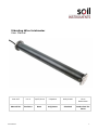
The instrument is protected inside a PVC housing and consists of a Vibrating Wire sensing
element in series with a calibrated spring which is, in turn, connected to the wire at one end and
a connecting rod at the other. In its assembled form, each end of the Jointmeter is fixed to a
PVC end block and M6 stud through a universal joint. The unit is fully sealed and operates at
external water pressures of up to 7 bar.
As the connecting rod is slowly pulled out from the gauge body, the spring is elongated causing
an increase in wire tension. This tension is directly proportional to the spring extension and the
joint opening can therefore be determined very accurately by measuring the change in the
tension in the wire using a Vibrating Wire readout unit.
Since sensing gauge itself is smaller than the protective PVC housing a degree of shearing
motion can be accommodated. This is achieved by the use of universal-joint connections on
each end of the gauge.
2.01 Preliminary Tests
Upon receipt of the instrument, the gauge should be immediately checked for proper operation
(including the thermistor, if included). Connect the gauge leads to the readout unit. Check and
record the gauge reading when the connecting rod end is pulled out approximately 3 mm.
A swivel ball joint between connecting rod and the spring protects the wire from damage due to
rotation of the connecting rod. As the ball joint is not entirely friction free rotation of the
connecting rod end may cause the wire to twist slightly before the ball rotates in the socket.
This twist in the wire will result in a change in reading. In severe cases the wire which has
torsional stresses added to pure tensile stresses induced by spring force will give a distorted
signal. Check the Jointmeter by pulling the connecting rod end out of the body in small steps.
At each pull out step a steady reading and clear ring of audio signal indicates a torsion free wire.
Check the calibration sheet to determine the gauge range and pull the rod out to its maximum
range. If the audio signal becomes dull with erratic reading during this check, the wire is under
torsional stress. This shall be cleared by pulling the connecting rod out to 20% of the stroke
and slowly releasing it. Slowly pull and release the rod a few times to help the ball turn in its
socket and eliminate twist in the wire. Repeat the check again and ensure that the Jointmeter
gives a clear steady signal throughout the range before it is installed.
User Manual
4
Section 3 : Installation
The installation is carried out in two separate operations.
The socket is first placed in the first lift of concrete and then, when the formwork is removed, its
protective plug is removed. The gauge is then screwed into the socket, extended slightly and
then concreted into the next adjoining lift.
3.01 Installing the Socket
The socket should be installed in the first lift of concrete. It is important that the face of the
socket must be coincident with the finished face of the concrete if it is to be accessible. The
socket is plugged, temporarily to prevent concrete entering the socket and to provide a support
for installation purposes.
The socket installation plug has an M8 threaded hole which is used to attach the plug and socket
to concrete formwork. If the socket is not installed in this manner, the threaded hole in the plug
should be sealed to prevent ingress of liquid concrete into the thread during pouring.
The socket can also be carefully welded to steel reinforcement or alternatively fixed with tie wire.
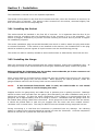
3.02 Installing the Gauge
After the formwork has been stripped and the socket exposed, remove the installation plug. At
this stage the inside of the socket should be thoroughly cleaned and lightly coated with grease.
Before pushing the Jointmeter into the socket, ensure that the pin in the connector rod
is inside the notch on the Jointmeter tube.
Place a small amount of thread-locking compound onto the threads of the stud on the connector
rod and push the gauge fully into the socket. While applying an inward pressure, rotate the
gauge clockwise until the rod is firmly fixed into the socket thread.
NOTE:
If the armoured direct-burial cable is used, the cable bundle or reel should
also be rotated to avoid crimping the cable.
Support and fix the gauge body and cable firmly in position prior to placing concrete. Readings
should be taken and recorded from the gauge (and thermistor) just after installation and prior to
placing the concrete. To allow for slight compression of the gauge it is recommended that the
gauge be set at approximately 25% of its range in tension. Remember that the gauge must not
be rotated after pulling it back from the socket. If the gauge has to be removed from the socket,
it should be pushed back in until the pin engages into the notch and then rotated counterclockwise until it comes loose. This may be difficult once the thread locking compound has set.
During connecting it is vital that the Jointmeter is protected from any damage. No vibrating
pokers or rodding of the concrete should be carried out near the Jointmeter. Concrete compaction
should be carried out by hand and with extreme care.
User Manual
5
3.03 Routing Cables
Cable should be protected to avoid damage during the placing and compaction of the concrete.
The cables from the instrument can be spliced onto armoured, direct burial cable which can be
safely routed through concrete without protection. Ensure that sharp kinks and bends are avoided
and that no rodding or vibrating pokers are allowed close to the cable.
3.04 Splicing
Because Vibrating Wire transducers output frequency or period, a direct derivative of frequency,
rather than current or voltage, slight variations in cable resistance have no effect on Jointmeter
readings. Consequently, splicing has no effect on instrument performance allowing cables to be
spliced and routed to junction boxes and then connected to multi conductor cables for
transmission to a central location.
Splicing should be carried out using an epoxy spicing kit and in accordance with the instructions
included in the kit.
3.05 Initial Data
Once the concrete has been placed and the initial set has been achieved, a ‘Base’ or ‘Initial’
Reading must be recorded. This value should be recorded in Period x 10 7 units and since it will be
used in the calculation of all subsequent readings, it is good practice to take a number of readings
and use the average value.
User Manual
6
Section 4 : Monitoring and Data Interpretation
Each Soil Instruments Vibrating Wire Jointmeter is calibrated and is supplied with a standard
Calibration Certificate giving the Gauge constant and information on atmospheric conditions at the
time of calibration.
Calibration is carried out by pulling out the connecting rod to full range while it is coupled to a
micrometer. (Slip gauges can also be used for this purpose by wedging them between the
connecting rod pin and the body tube). Readings are taken at full range displacement/extension, a
number of intermediate points and at zero extension. The gauge factor is then calculated using
the expression given in the Calibration Certificate specimen.
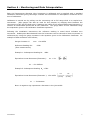
Following the installation instructions the reference reading is noted which indicates zero
movement. Subsequent data obtained from the Jointmeter can be reduced to linear movement in
millimetres by using the gauge constant in the equation given in the Calibration Certificate. An
example of data reduction is as follows;
Gauge Constant: K
mm: -120.4254
Reference Reading No:
6320
(Zero measurement)
Example 1: Subsequent Reading N1:
4820
Equivalent Linear Movement (Extension):
L
=Kx
10 7 10 7
2 2
N o N1
L = 21.685mm
Example 2: Subsequent Reading N2: 6740
10 7
10 7
Equivalent Linear Movement (Extension ): -120.4254
{6320}2 {6740}2
L
= -3.6404mm
Note: A negative sign represents a decrease in the joint width.
User Manual
7
4.01 Temperature Correction
The Jointmeter working elements are made primarily of steel and stainless steel and are affected
by changing temperature to a certain predictable degree. In case of large temperature changes
application of temperature correction will improve the accuracy of the measurements. The
approximate temperature effect on the gauge is -0.02mm per degree Celsius.
Hence for a temperature increase of 10° C Jointmeter will indicate (-0.02 x 10) -0.2mm reduction
in linear measurement. Correction is applied by adding 0.2mm to the result indicated by the
Jointmeter reading. A fall in temperature will result in a positive change in linear measurement
which can be corrected accordingly.
Physical dimensional changes due to temperature in the Jointmeter and the structure on which it
is mounted are of the order of 10-6m/m/°C and can be neglected.
Barometric pressure changes do not affect the Jointmeter reading.
4.02 Environmental Factors
Since the purpose of the Jointmeter installation is to monitor site conditions, factors which may
affect these conditions should always be observed and recorded. Seemingly minor effects may
have a real influence on the behaviour of the structure being monitored and may give an early
indication of potential problems. Such factors include but are not limited to: blasting, rainfall,
tidal levels, excavation and fill levels and sequences, site traffic, temperature and barometric
changes, changes in personnel reading the instruments, nearby construction activities and
seasonal changes.
User Manual
8
Section 5 : Troubleshooting
If a failure of any Vibrating Wire transducer or the electrical cable is suspected, the following steps
can be followed. The transducers themselves are sealed and cannot be opened for inspection.
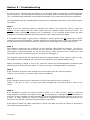
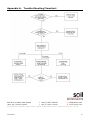
The “Troubleshooting Flowchart” should also be followed if any instrument failures are suspected.
The steps below and the Troubleshooting Flowchart are applicable generally to any Vibrating Wire
instrument.
STEP 1
Before any of the following steps are followed, the readout unit should be used to verify the
stability of the reading and the audio signal from the portable logger should be heard. An
unstable (wildly fluctuating) reading from a transducer, or an unsteady audio signal are both
indications of possible problems with instruments or their related electrical cables.
If a portable data logger is giving faulty readings or audio signals from all transducers, a faulty
readout unit must be suspected. Another readout unit should be used to check the readings from
the transducers and Soil Instruments Ltd. should be consulted about the faulty readout unit.
STEP 2
The resistance across the two conductors of the electrical cable should be checked. This can be
done using a multimeter device across the two exposed conductors if the cable has not been
connected to a terminal cabinet, or can be done just as easily across the two conductors if the
instrument has been connected to such a terminal (or datalogger).
The resistance across the two conductors should be approximately of the order of 120° to 180°
The majority of this resistance will come from the transducer (say approximately 130°).
Before proceeding to Steps 3 and 4, the continuity should be checked between conductors and
earthing screen of the electrical cable. If continuity exists, a damaged cable is confirmed.
STEP 3
If the resistance across the two conductors is much higher than the values quoted in
“STEP 1” (or is infinite), a severed cable must be suspected.
STEP 4
If the resistance cross the two conductors is much lower than the values quoted in
“STEP 1” (say 80° or less) it is likely that cable damage has occurred causing a short in the
circuit.
STEP 5
If the resistance is within the values quoted in “STEP 1” (i.e. 120° to 180°), AND no continuity
exists between conductor and earth screen and on checking the reading from the transducer, it
proves to be still unstable or wildly fluctuating, it must be assumed that the integrity of the circuit
is good. A faulty transducer could be suspected if neighbouring construction activities do not
account for the anomaly Soil Instruments should be consulted.
If the point at which the cable is damaged is found, the cable can then be spliced in accordance
with recommended procedures.
User Manual
9
Appendix A. Trouble Shooting Flowchart
Bell Lane, Uckfield, East Sussex
t: +44 (0) 1825 765044
e: [email protected]
TN22 1QL United Kingdom
f: +44 (0) 1825 744398
w: www.itmsoil.com
Soil Instruments Ltd. Registered in England. Number: 07960087. Registered Office: 5th Floor, 24 Old Bond Street, London, W1S 4AW
User Manual
10