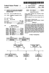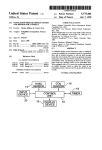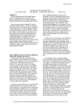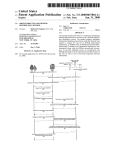
1
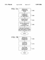
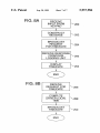
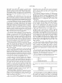
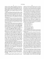
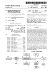
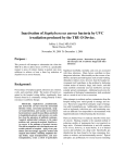
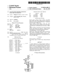
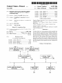
US005957986A
Ulllted States Patent [19]
[11] Patent Number:
Coverdill
[45]
[54]
Date of Patent:
METHOD AND SYSTEM FOR RECORDING
5,303,163
4/1994 Ebaugh et a1. ........................ .. 340/439
5,526,269
5,452,446
6/1996
9/1995 Johnson
Ishibashi .......
et 211...
-
-
[75]
Inventor‘
[73]
Assigneez Freightliner Corporation, Portland,
Cary N‘ Coverdln’ Bonng’ 0mg‘
5,594,646
1/1997
ItOll et a1. ..... ..
5,600,558
2/1997
Mearek et al. ........................ .. 340/438
5,650,930
7/1997 Hagenbuch ............................. .. 701/35
5,802,545
9/1998 C0verd1ll ................................ .. 701/35
OregNotice;
OTHER PUBLICATIONS
This patent is Subject to a terminal disClaitmm
Owner’s Manual Caterpillar Driver Information Display,
Caterpillar, Feb. 1995.
ProDriverTM User Manual, Detroit Diesel Corporation,
[21] Appl. NO.Z 09/137,553
[
22
1
*Sep. 28, 1999
VEHICLE
STANDARD
DATA
TIME
RELATIVE TO VEHICLE
_
[*]
5,957,986
F1 d:
16
A
Man’ 1994
CELECT RoadRelayTMUser’s Guide, Curnrnins Cadec.
.20 1998
ug
’
Primary Examiner—Gary Chin
Related US Application Data
Attorney, Agent, or Firm—Klarquist Sparkrnan Campbell
Leigh & Whinston LLP
7
63
7
Continuation of a
Pat. NO. 5,802,547577
lication No. 08 652 776 Ma 23 1996
/
7
7
y
7
7
[57]
ABSTRACT
[51]
Int. Cl? .................................................... .. G06F 17/00
A master clock on a truck maintains Vehicle Standard time
[52]
us. Cl. .............................. .. 701/35; 701/29; 340/438
for the Purposes of monitoring 919 recording Vehicle Per
[58]
Field Of Search ...................... .. 701/29 35- 340/438
’ ’ 340/439’
formance data throughout the Vehlcle' Vehlcle Performance
data is stored for a prede?ned period of time in response to
detecting prede?ned events. Instances of vehicle perfor
[56]
References Cited
rnance data are time stamped with vehicle standard time.
The master vehicle clock can also maintain the local time
US. PATENT DOCUMENTS
displayed to the driver. In response to inputs from the driver,
4,258,421
3/1981 JuhasZ et a1. ........................... .. 701/35
4,533,962
8/1985 Decker et a1.
360/5
10/1993
Koyanagi
time is. computed and the updated local time is displayed to
701/35
5,173,856 12/1992 Purnell et a1.
5,250,761
the difference between driver local time and Vehicle Standard
.........
..
the driver.
701/35
5,253,224 10/1993 Van Doesburg ...................... .. 340/438
3 Claims, 7 Drawing Sheets
20w
22?
DATA MEASURING
DEVICE
DATA MEASURING
DEVICE
I
I
DATA LOGGING
DEVICE
j
26
l
I
I
DATA MEASURING w
DEVICE
24
7
LOCAL TIME
DISPLAY
D
A
AI
30
7
I
I
I
MASTER
CLOCK
INPUT
CONTROL
/
28
/
32
l
U.S. Patent
Sep.28, 1999
Sheet 1 of7
5,957,986
FIG. 1
20w
22?
DATA MEASURING
DEVICE
DATA MEASURING
DEVICE
I
I
DATA LOGGING
DEVICE
q
26
I
LOCAL TIME
DISPLAY
‘9
I
I
(
I
I
I
DATA MEASURING w
DEVICE
24
so
I
I
I
I
I
MASTER
CLOCK
INPUT
CONTROL
28
32
l
U.S. Patent
Sep.28, 1999
(- DOOR
94 SENSORS
Sheet 3 of7
HVAC
SENSORS
5,957,986
PARKING
q
BRAKE SENSORS 98
\
COOLANT
96
F|G.3
LEVEL ‘W
SENSOR 10o
A/D
__ Vg?’?g w
/OONvERTERS
SENSOR 102
106
TLIRN
SIGNALS w
104
110w
TO DATA
F LOGGING UNIT
903
:
DISPLAY
KEYPAD
DEVICE
“92
82
MEMORY
8O
J
ROM
F
~
‘
‘E
38
‘
CPU
‘
PORT
EEPFKDMw
86
“
INTERFAOE 84
k
/
40
2
108
"
BUZZER
U.S. Patent
Sep. 28, 1999
FIG. 7A
5,957,986
Sheet 6 0f 7
RECEIVE
TIME/DATE
DATA
I
COMPUTE
CHANGE
IN TIME/DATE
x262
CONSTRUCT
MESSAGE
\ 264
I
SEND MESSAGE
TO DATA
LOGGING UNIT
RECEIVE UPDATE
IN TIME/DATE FROM
DATA LOGGING UNIT
II
END
FIG. 78
RECEIVE
MESSAGE
FROM ICU
I
UPDATE
DELTA IN
BUFFER
I
RETURN
TIME/DATE
MESSAGE
I
END
\ 270
U.S. Patent
Sep. 28, 1999
FIG. 8A
Sheet 7 0f 7
RECEIVE
INPUT FROM
KEYPAD
II
CONSTRUCT
MESSAGE
I
BROADCAST
REQUEST
FOR TIME/DATE
II
RECEIVE RESPONSE
FROM DATA
LOGGING UNIT
II
DISPLAY
TIME/DATE
V
END
FIG. 88
RECEIVE
REQUEST FOR
TIME/DATE
II
COM PUTE
DRIVER LOCAL
TIME
V
BROADCAST
TI ME/DATE
V
END
5,957,986
5,957,986
1
2
METHOD AND SYSTEM FOR RECORDING
VEHICLE DATA RELATIVE TO VEHICLE
STANDARD TIME
standard time and for conveniently displaying local time in
the cabin of the vehicle. The invention further provides a
master clock for maintaining vehicle standard time, and a
system for recording vehicle data. In this context, vehicle
RELATED APPLICATION DATA
standard time refers to a time reference or time standard in
a truck against Which the timing of performance data mea
sured throughout the vehicle may be recorded. Vehicle
This application is a continuation of US. application Ser.
No. 08/652,776, now US. Pat. No. 5,802,545, entitled
standard time can also serve as a reference point for com
METHOD AND SYSTEM FOR RECORDING VEHICLE
DATA RELATIVE TO VEHICLE STANDARD TIME, by
Cary N. Coverdill, ?led May 23, 1996, Which is hereby
puting the local time displayed to the driver. Vehicle local
10
FIELD OF THE INVENTION
The invention relates generally to data management and
storage systems for vehicles, and more speci?cally relates to
a vehicle clock capable of maintaining standard vehicle time
15
vehicle standard time, and also maintains driver local time.
One speci?c Way to maintain driver local time is to keep
track of the difference betWeen the local time and the vehicle
time, and compute the local time, upon request, from the
vehicle standard time and the difference value.
In one embodiment, a truck includes a data logging device
and a driver local time.
BACKGROUND OF THE INVENTION
time is variable and is typically adjusted by a driver as a time
Zone is passed. In one embodiment, a master clock maintains
incorporated by reference.
20
for recording vehicle performance data relative to vehicle
standard time. The data logging device monitors vehicle
performance data such as road speed, engine speed, coolant
In the trucking industry, it is important to accurately
temperature, etc. provided by data measuring devices
maintain time for the bene?t of both the driver and for
service technicians. Since a truck driver frequently travels
across time Zones, it is helpful to provide a clock in the cabin
that is easy to change With the change in time Zones. In vieW
of this fact, it is quite common for trucks to have clocks in
the cabin that display time and can be reset to the local time.
Aside from the convenience to the driver, it is also useful to
have a clock for keeping track of vehicle operating and
diagnostic data. For example, if a problem occurs in the
throughout the vehicle. In the process of recording selected
data, the data logging device stamps instances of the data
With the vehicle standard time from a master vehicle clock.
25
Time stamping refers to the process of associating vehicle
standard time With the data. This master clock in this
embodiment also maintains driver local time by keeping
the problem actually occurred at another time. This can
track of the difference betWeen local time and vehicle
standard time.
A local time display presents the local time in the cabin in
the vehicle. If the driver Wants to change the local time, he
or she simply increments or decrements the time through an
input control. Changes in local time are communicated to the
master clock. In one speci?c implementation, the input
control and time display are integrated into an instrument
control unit. This instrument control unit communicates
changes in local time to the master clock, Which keeps track
of the current difference betWeen vehicle standard time and
driver local time.
Further advantages and features of the invention Will
become apparent With reference to the folloWing detailed
result When an electronic subsystem in a truck records a fault
description With reference to the accompanying draWings.
30
transmission, it is useful to knoW precisely When the prob
lem occurred. Many of the sophisticated electronic controls
in trucks do have a mechanism for keeping track of time.
Despite the presence of these electronics on board the truck,
the frequent changes in local time and/or the lack of a
consistency among time keepers in the vehicle often leads to
confusion in identifying When problems on the truck actu
35
ally occurred.
This confusion arises, for example, When a driver tells the
service technician that a problem occurred at one time and
using a time clock that is not consistent With the driver’s
time or time used by other subsystems in the vehicle.
It is equally confusing When a fault in a subsystem is
40
45
FIG. 1 is a functional block diagram illustrating a vehicle
data recording system of an embodiment of the invention.
FIG. 2 is a block diagram illustrating the architecture of
recorded at one time in a ?rst time Zone and then is recorded
again at the same time in a second time Zone. Consider for
example, a truck travelling West from South Bend, Ind. to
Chicago, Ill. If faults are recorded in terms of local time,
either by the driver or the truck’s electronics, it is possible
data management system on a vehicle.
50
to record a fault at 2:00 PM. in South Bend and a second
fault at 2:00 PM. in Chicago. The resulting data erroneously
shoWs that the fault occurred tWice at the same time, When
in reality, they occurred one hour apart.
BRIEF DESCRIPTION OF THE DRAWINGS
55
FIG. 3 is a block diagram illustrating an embodiment of
an instrument control unit in the data management system.
FIG. 4 is a diagram of the keypad of the instrument
control unit shoWn in FIG. 3.
FIG. 5 is block diagram illustrating the data logging unit
The problems outlined above occur because of the lack of
effective means for displaying and keeping track of time in
in one embodiment of the invention.
the truck. The dif?culty in diagnosing problems in the
screens used to set or change drive local time.
vehicle are further frustrated by the lack of effective systems
for tracking and recording faults detected in the truck. In
general, there is a need for an effective system for tracking
and recording events on a consistent basis and most prefer
ably across all subsystems installed in a truck.
SUMMARY OF THE INVENTION
The invention provides a method for accurately recording
vehicle performance data relative to a master or vehicle
FIG. 6 is a diagram illustrating one example of the display
60
FIGS. 7A and 7B are How diagrams illustrating a process
for setting the driver local time in one embodiment.
FIGS. 8A and 8B are How diagrams illustrating the
process for displaying local time in one embodiment.
DETAILED DESCRIPTION
65
FIG. 1 is a functional block diagram illustrating a vehicle
data recording system of an embodiment of the invention.
5,957,986
3
4
The system includes a plurality of data measuring devices
change the local time displayed in the cabin. In one speci?c
embodiment, changes in local time are communicated to the
(eg 20, 22, or 24) for measuring vehicle performance data.
Vehicle performance data can include a variety of vehicle
operating, trip, maintenance or diagnostic data such as oil
master clock, Which maintains the current difference or
pressure, road speed, fuel rate, coolant level, coolant
temperature, battery voltage, odometer etc. In addition, such
detail regarding a speci?c implementation of the system in
“delta” betWeen vehicle standard time and local time. More
FIG. 1 folloWs beloW.
FIG. 2 is a block diagram illustrating the system archi
tecture in a more speci?c implementation of the system
shoWn in FIG. 1. The system architecture includes a number
vehicle performance data can include fault data such as oil
pressure loW, coolant temperature high, high intake manifold
air temperature, electrical system or subsystem failure, etc.
The vehicle performance data can be measured indirectly via
sensors controlled by electronic control units, or directly via
10
discrete sensors or input devices.
The data logging device 26 monitors vehicle performance
data and potentially records selected instances or “slices” of
this data. As alluded to above, the data logging device can
receive the vehicle performance data either directly from a
15
of electronic control units (ECUs) coupled together in With
a data link 40. In particular, the system includes an instru
ment control unit 42, used to control instruments and gauges
at the dash of the truck, and a data logging unit 44, used to
monitor and record events reported on the data link 40. The
illustrated system architecture also includes a number of
other electronic units as shoWn, such as a poWertrain ECU
46, an air suspension ECU 48, an antilock brake ECU 50,
data measuring device such as a discrete sensor or input
and an air conditioning protection unit 52. An ECU typically
device, or indirectly through messages from electronic con
includes a microprocessor, memory and one or more sensors
trol units on a data link. For example, sensors can include a
coolant level sensor, a battery voltage sensor, an input device
located in the cab of the truck etc. Similarly, the data logging
20
device 26 can be coupled to one or more electronic control
units that measure performance data and transfer it to the
data logging device via a data link.
The data logging device 26 can be programmed to record
selected vehicle performance data in response to events. An
25
control units. For instance, a data measuring device can be
30
implemented in an electronic control unit, equipped With
sensors for measuring vehicle performance data. As another
example, a data measuring device can be implemented as a
35
The master clock 28 is a time keeping device that main
tains vehicle standard time on the truck. Vehicle standard
time refers to a shared time resource or reference that
monotonically increases from a starting time, and acts as a
time reference for instances of vehicle data and events. The
master clock can be located in a variety of locations in the
logging unit 44. The input control and the local time display
data measuring devices may correspond to the electronic
manually triggered event initiated by the driver. When used
in conjunction With the time tracking devices in the system,
this type of event is useful for tracking precisely When the
driver experiences problems.
device and master clock are incorporated into the data
are features of the instrument control unit 42. Finally, the
event can be a fault detected in the vehicle such as coolant
level loW or electrical subsystem failure. In addition, an
event can be a manually triggered signal or data message
sent to the data logging device. For instance in one speci?c
embodiment described further beloW, one type of event is a
and actuators (54, 56, 58, 60, 62 and 64 for example) used
to control and/or monitor truck performance.
As one possible implementation, the devices depicted in
FIG. 1 can be implemented in the system architecture shoWn
in FIG. 2. In one embodiment, for example, the data logging
40
discrete sensor directly coupled to the data logging unit.
More detail regarding the instrument control unit and data
logging unit folloWs beloW.
The system architecture in FIG. 2 also includes a data port
70 for coupling external devices to the on-board data link.
This data port 70 enables an external computer to receive
and transmit messages on the data link. It also enables an
external computer to establish a connection With an ECU on
the netWork to either doWnload data or retrieve data from
memory of an ECU on the data link.
truck. For instance, it can function as a stand alone device or
The data link 40, in this implementation, is a serial
can be incorporated into the data logging device 26, or other
communication path connecting the ECUs together. This
electronic control device in the vehicle such as an engine
45 particular data link is designed according to SAE 11708, a
computer or an instrument control unit in the cabin. In one
standard for serial data communication betWeen microcom
embodiment, the master clock communicates vehicle stan
dard time to the data logging device so that the data logging
device can record the performance data relative to vehicle
standard time.
In addition to keeping vehicle standard time, the master
clock can also provide driver local time, Which may or may
not differ from the vehicle standard time. In one speci?c
embodiment, the master clock maintains driver local time by
storing the difference betWeen driver local time and vehicle
standard time.
The local time display 30 shoWn in FIG. 1 displays the
driver local time in the cab of the truck. It can receive the
local time either directly or indirectly from the master clock
28. In one speci?c embodiment, the local time display
receives the local time via the data logging device 26.
The input control 32 enables the driver to control the
display of driver local time. Located in the cabin of the
truck, the input control enables the driver to increment or
decrement the local time. For example, if the truck passes
through a time Zone, the driver can change the local time
easily by simply pressing a button on the input control to
puter systems in heavy duty vehicle applications. While this
speci?c embodiment is based on the 11708 standard, it is not
critical that the invention be implemented in this speci?c
50 manner. One possible alternative is to use a data link
55
constructed according to SAE 11939.
In one speci?c embodiment, the data link 40 is comprised
of a tWisted pair cable operating at 9600 baud. Designed
according to the SAE 11708 standard, the data link forms a
communication channel among electronic control units
coupled to it. Electronic control units generate a digital
signal on the data link by applying a voltage differential
betWeen the tWo Wires in the cable. A voltage differential
above a speci?ed threshold represents a logic high value,
60
65
While a voltage threshold beloW a speci?ed threshold rep
resents a logic loW value. This type of data link is particu
larly advantageous for hostile environments because the
signal is more robust and impervious to signal degradation.
HoWever, other alternative communication media could be
used in place of the 11708 cable.
The ECUs connected on the netWork communicate With
each other according to protocols de?ned in SAE 11708 and
5,957,986
5
6
SAE 11587. The SAE 11587 standard is entitled “Joint
Preferably located at the dash of the truck, the instrument
SAE/TMC Electronic Data Interchange BetWeen Micro
control unit can include the input control that enables a
computer Systems and Heavy Duty Vehicle Applications.”
driver to display driver local time and to change the dis
played time as Well.
The instrument control unit includes a CPU 80, memory
82 and a port interface 84 for connecting the unit to the data
link 40. The memory includes programmable ROM
(EEPROM) 86 and permanent ROM 88. The routines for
controlling the ICU are stored in ROM 88, While con?g
This standard de?nes the format of data and messages
communicated among microprocessors connected to a
shared data link, and is speci?cally adapted for use With
SAE 11708.
According to SAE 11708/11587, the ECUs on the data
link communicate by passing messages to each other. The
ECUs can be either receivers, or receivers and transmitters.
In this particular implementation, the instrument control unit
10
and the data logging unit are both transmitters and receivers.
Amessage includes the folloWing: 1) a module ID (MID),
urable data such as a con?guration ?le is stored in the
EEPROM 86.
The ICU also includes an input device 90 and a display
as identi?ed in SAE 11587. The MID portion of a message
device 92. In this implementation, the input device 90 is a
ten key keypad, and the display device 92 presents a
tWo-line display, sometimes referred to as the “message
center.” In one implementation, the display device com
prises a tWo by 20 character vacuum ?uorescent display.
speci?es the origin or transmitter of the message. In the
Alternative implementations are also possible such as a
2) one or more parameters, and 3) a checksum. The number
of parameters in a message is limited by the total message
length de?ned in the SAE 11708 standard. The message
identi?cation numbers are assigned to transmitter categories
15
majority of cases, messages are broadcast on the data link
Without specifying a receiver. HoWever, the message format
20
The ICU can be connected to a number of sensors
can be eXtended to include the MID of a receiver after the
(94—104) through analog to digital converters 106. For
eXample, the ICU in this implementation is coupled to: door
MID of the transmitter for special applications.
The messages passed among the ECUs to convey infor
mation by one or more parameters contained Within the
messages. According to the SAE 11587 standard, the ?rst
character of every parameter is a parameter identi?cation
sensors (94) for detecting When the cab doors are open or
25
character (PID). The parameter identi?ed by the PID directly
folloWs the PID. The SAE 11587 supports different data
formats including a single character, a double data character
or more than tWo data characters representing the parameter
data. Several parameters can be packed into a message,
limited by the maXimum message siZe as noted above.
30
other over the data link according to the SAE standard
and turn signal controls (104) Which indicate When a turn
The ICU can also include a buZZer 108 used to notify the
35
driver When certain Warning conditions are detected. Typical
eXamples of these Warning conditions include “cab door
open,” “parking brake applied and vehicle in motion,”
“coolant level loW,” etc. In this implementation, the buZZer
also de?nes a method for resource contention among the
ECUs on the data link.
An ECU Wishing to transmit data on the data link ?rst
Waits for a lull in transmission of data on the data link. In this
closed; HVAC sensors (96) for determining Whether fresh
air is circulating in the cab; parking brake controls (98) for
sensing Whether the parking brakes are applied; a coolant
level sensor (100) for detecting When the coolant level drops
beloW a speci?ed level; Wiper ?uid sensors (102) for deter
mining When the Wiper ?uid drops beloW a speci?ed level;
signal is applied.
In this implementation, the ECUs communicate With each
11708. The standard describes methods for accessing the
data link and constructing messages for transfer over it. It
Liquid Crystal Display (LCD) or raster display device.
is integrated into the ICU. HoWever, a buZZer or other audio
transducer can be implemented as a discrete device to the
40
ICU.
The particular ICU used in this implementation is manu
particular implementation, the length of the lull is 200
milliseconds. After detecting this lull, the ECU attempts to
factured by Joseph Pollak of Boston, Mass. for Freightliner
transmit its message. The transmitter broadcasts its message
onto the data link. Each of the ECUs that operate as receivers
on the data link Will receive the message. HoWever, receiv
replacement part from Freightliner Corporation.
Corporation. The instrument control unit is available as a
45
FIG. 4 is a diagram of one implementation of the keypad.
The keypad includes the folloWing dedicated keys:
ers only act on a message if programmed to do so.
In some cases tWo or more transmitters may attempt to
broadcast a message at one time, giving rise to a collision.
To resolve a con?ict among transmitters, messages have a 50
1. Time
priority according to their message identi?ers. The PIDs of
higher priority parameters have a greater number of bits set
at a logic level one. When more than one message is
broadcast at a time, the more dominant message takes
priority over lesser dominant messages. Since a loWer pri
55
ority message is blocked by a higher priority message, the
(120)
2. Temperature
(122)
3. Fuel
(124)
4. Trip (miles, hours and fuel)
5. Leg (miles, hours and fuel)
(126)
(128)
The keypad also includes the folloWing general purpose
keys:
transmitter of the loWer priority message Waits and retrans
mits the message after another lull. An ECU on the data link
Will continue to attempt to send a message until it is
successfully broadcast to the data link.
60
While this particular embodiment is implemented accord
ing to the SAE 11708 standard, this is only one eXample a
suitable data link implementation. Other alternatives are
possible as Well. For eXample, the data link can be imple
mented according to SAE 11939.
FIG. 3 is a block diagram illustrating the instrument
control unit (ICU) in an embodiment of the invention.
1. Left ArroW Key
2. DoWn ArroW Key
(130)
(132)
3. Right ArroW Key
4. Set/Reset Key
(134)
(136)
The keypad includes an event key 138 Which enables the
driver to specify that an event or problem has occurred With
65
the vehicle. For eXample, if the driver is experiencing
problems With the transmission, he can depress the event key
to record data associated With the transmission problem. In
5,957,986
7
8
response, the data logging unit 44 (FIG. 2) receives an
example as the truck passes through time Zones, the vehicle
standard time does not change With changes in the local
interrupt signal from the keypad 90 of the ICU (FIG. 3) and
creates an event ?le. In this implementation, there is a
time. Instead, the vehicle standard time monotonically
increases from an origin. Vehicle standard time is helpful in
recording faults and events because it prevents ambiguity in
discrete connection 110 from the keypad 90 to the data
logging unit 44. In addition, the ICU can send a message to
the data logging unit over the data link 40 to notify it that the
tracking When these faults or events occurred relative to
driver or other user has triggered a manual event at the
keypad 90.
Using the keypad, a user such as the driver or other
operator is able to display and set driver local time. In this
particular embodiment, the ICU displays driver local time in
10
response to an input received from the “time” key in the
keypad. Driver local time includes the time in hours and
minutes (hh:mm AM. or PM.) and the date (month day,
year). The time and date can be displayed at any time in
response to the “time” key so long as the poWer to the dash
of the truck is on.
To change or set the driver local time in this embodiment,
the user presses a sequence of keys on the keypad to retrieve
a set-up screen. For safety reasons, the set-up mode of the
15
minute, every second, or only When a prede?ned event is
detected. Some examples of the data monitored by the data
Further detail regarding setting and changing driver local
time is provided beloW. Any available local time resetting
approach may be used.
FIG. 5 is block diagram illustrating the data logging unit
logging unit are set forth beloW. The name of the parameter
is folloWed by the parameter identi?cation number (PID) as
set forth in the SAE J 1587 standard.
25
the data logging unit incorporates the data logging device
and master clock shoWn in FIG. 1. The data logging unit 180
generally includes memory 182, a microcontroller 184, an
interface 186 to the data link, a real time clock 188, and a
poWer supply 190. The memory 182 and the real time clock
Vehicle Road Speed; PID 84
Percent Throttle; PID 91
Percent Engine Load; PID 92
Output Torque; PID 93
Engine Oil Pressure; PID 100
Turbo Boost Pressure; PID 102
Coolant Temperature; PID 110
are coupled to the microcontroller 184 via a bus 192.
Engine Speed (RPM); PID 190
The poWer supply 190 includes a chip that supplies poWer
to the microcontroller from either the vehicle battery or a
lithium battery or other back up poWer supply. The lithium
battery serves as a back-up in the event that the voltage
supplied from the battery is insuf?cient or unavailable.
as a FIFO buffer. In this implementation, the data logging
unit is programmed to continuously store the most recent 60
seconds of data from the data link. Instances of vehicle
performance data can be captured at different intervals. For
example, data can be captured once a minute, tWice a
ICU can only be activated When the parking brake is applied.
in one embodiment of the invention. In this implementation,
each other. Further detail regarding the operation of the
master clock and the local time display is provided beloW.
As introduced above, the data logging unit performs a
data monitoring function. Coupled to the data link, the data
logging unit listens for periodic data messages broadcast
over the data link, and continuously records a snapshot of
data from the data link into a temporary storage device, such
The data logging unit captures instances of selected data
35
once every second and stores it in the buffer. When the buffer
is full, the most recent second of data overWrites the oldest
snapshot of data.
In addition to continuously storing slices of selected data,
the data logging unit also monitors prede?ned events. These
As noted above, the data logging unit is coupled to the
keypad 90 of the ICU (FIG. 3) to receive an interrupt When
a user actuates the event key on the keypad. This connection
events can be de?ned by a PID broadcast on the data link,
or by a discrete signal (such as an interrupt) received at the
data logging unit. When one of the prede?ned events occurs,
the data logging unit stores the last 60 seconds Worth of data
is represented by the manual trigger sWitch 194 shoWn in
FIG. 5. The data logging unit can also receive interrupts
from other devices as Well. The keypad of the ICU could
also be coupled to the data logging unit to communicate
to memory and begins storing data folloWing the event, such
signals representing changes in driver local time. For
as the next 60 seconds Worth of data. In total, the amount of
example, a key or keys on the keypad could be con?gured
to send signals to the data logging unit to update or modify
45 data stored for an event includes tWo minutes and one
local time, or the delta betWeen vehicle standard time and
data is recorded in an event ?le in memory. An external
local time, stored in the data logging unit.
The memory 182 of the data logging unit includes both
RAM 196 and ROM 198. This implementation includes 128
KB of ROM, Which stores the application code executed by
the microcontroller. This executable code includes the set-up
routines used to boot the data logging unit and the data
logging routines used to monitor prede?ned events. This
implementation also includes 256 KB of battery-backed
computer can be used to extract one or more of these event
second Worth of data in this particular implementation. This
?les from the data logging unit for diagnostic purposes.
As noted above, the system architecture on-board the
vehicle maintains both vehicle standard time for tracking
events and faults and driver local time for display to the
driver. In the implementation described and illustrated
55
above, the data logging unit maintains vehicle standard time
and the difference (delta) betWeen vehicle standard time and
RAM, Which is used to implement a FIFO buffer for
capturing data from the data link, to store event ?les and to
driver local time. In response to a request to display local
time at the keypad, the ICU issues a request for the time. The
store a device parameter ?le.
data logging unit then returns the appropriate time to the
The data logging unit can monitor vehicle performance
data from the data link or from discrete sensors coupled
FIG. 6 is a diagram illustrating one example of the display
directly to it. For example, the data logging unit monitors
screens used to set or change driver local time. This diagram
voltage supplied by the vehicle battery through an analog to
shoWs a series of display screens as Well as the keys on the
digital converter 200, Which converts the 12 volt signal from
the battery to a digital signal compatible With the microcon
troller 184.
keypad used to change screens and enter data. Starting With
The real time clock maintains vehicle standard or refer
ence time. Though the driver local time may be reset, for
the setup screen 220, the user accesses time/date setup
65
screens by using the arroW keys (222—226 for example) on
the keypad as shoWn. The user begins by scrolling through
setup screens 228 to reach the main time/date screen 230.
5,957,986
9
When the user reaches the main time/date screen 230, he
-continued
or she can then set the minutes (232), hours (234), day (236),
month (238) and year (240) using the set key 242 and left
and right arrow keys 244, 246, for example. To exit the
Byte
Type
Resolution
Valid Range
Month
Signed Short
1 month/bit
—12 to +12 months
Year
Signed Short
1 year/bit
—127 to +127 years
time/date screens, the user can press the doWn arrow key
Integer
(248 for example). FIG. 5 represents only one example of
Integer
one implementation of a user interface for the ICU. A
number of other approaches are possible as Well.
FIGS. 7A and 7B are How diagrams illustrating a process
for setting the driver local time in one embodiment. FIG. 7A
Example:
10
140 254 179 4 30 FC 00 00
Checksum
illustrates the steps executed by the ICU, and FIG. 7B
illustrates the steps executed by the data logging unit.
The Example shoWs the ICU sending a negative change of
The process begins When a user changes the time or date
from the setup screens as described above. The ICU receives
the data entered at the keypad When the user presses the set
key (260). It then computes the change in time or date of the
one day to the data logging unit date buffers.
As set forth in the above message speci?cations, the ICU
sends the change in time and/or data to the data logging unit
driver local time (262). The ICU then constructs a message
by specifying its MID (266). The data logging unit receives
to send to the data logging unit (264). Depending on What
the message or messages from the ICU (268, FIG. 7B), and
in response, updates values in a buffer for storing the
difference (delta) betWeen vehicle standard time and driver
the user changes, a message or messages can be sent for the
change in time, the change in date, or changes in both the
20
time and date.
local time (270). In this particular implementation, the
The speci?cation for one implementation of the change in
battery backed RAM in the data logging unit includes this
memory buffer. The data logging unit adds a signed change
time is set forth beloW.
in time to the cumulative time “delta” or “offset” stored in
25
Delta Time Change
Priority:
8
Update Period: As needed
Format:
MIDiCluster
MessageiLength
254
31
MIDiDatalogger
MinuteiByte
HouriByte Checksum
30
the buffer. Similarly for a change in date, it adds a signed
change in date to the cumulative date value stored in the
buffer.
As an alternative to communicating changes in local time
over the data link, the keypad of the ICU can be directly
connected to the data logging unit to transfer data repre
senting changes in local time. In response, the data logging
Where MinuteiByte and HouriByte are as de?ned beloW:
35
Byte
Type
Resolution
Valid Range
Minute
Signed Short
1 minute/bit
—60 to +60 minutes
1 hour/bit
—24 to +24 hours
(272). In this particular implementation, the data logging
unit issues a message using the J 1587 standard parameters,
PID 251 in the case of an update in time, or PID 252 in the
Integer
Hour
Signed Short
Integer
unit Would then update the time/date buffer as described
above.
After updating the buffer, the data logging unit sends a
message, transferring the updated time or date to the ICU
40
case of an update of the date.
The speci?cation for PIDs 251 and 252 used in this
embodiment are set forth beloW.
Example:
140 254 179 3 31 01 00
Checksum
PID 251 — Clock
45
Example requests displayed time be incremented by one
minute.
The speci?cation for one implementation of the change in
Parameter Data Length:
Data Type:
3 Characters
Each Character — Unsigned Short Integer
Resolution:
Character 1 = 0.25 s/bit
Character 2 = 1 min/bit
Character 3 = 1 h/bit
date is set forth beloW.
50 Maximum Range:
Character 1 = 0 to 63.75 s
Character 2 = 0 to 255 min
Character 3 = 1 h/bit
Delta Date Change
Transmission Update Period:
Message Priority:
Priority: 8
Update As needed
Format:
Period:
On request
8
PID
Data
55
nabc
Format: MIDiCluster 254 MIDiDatalogger
MessageiLength 30 DayiByte MonthiByte YeariByte
Number of parameter data characters = 3
Seconds (not displayed in this
Checksum
implementation)
Minutes
Where DayiByte, MonthiByte, and YeariByte are as
de?ned beloW:
Byte
Type
Resolution
Valid Range
Day
Signed Short
0.25 day/bit
—31.75 to +31.75
Hours
60
PID 252 — Date
Parameter Data Length:
Data Type:
Resolution:
Integer
days
65
3 Characters
Each Character — Unsigned Short Integer
Character 1 = 0.25 day/bit
Character 2 = 1 month/bit
Character 3 = 1 year/bit
5,957,986
Maximum Range:
11
12
-continued
implementation, the data logging unit computes driver local
time by adding the cumulative offset stored in the buffer to
the vehicle standard time provided by the real time clock
(288). Similarly, it computes the date to be displayed With
driver local time by adding the cumulative offset for the date
to the date provided by the real time clock (288).
After computing driver local time, the data logging unit
Character 1 = O to 63.75 day
Character 2 = O to 255 month
Character 3 = O to 255 year
Valid Range:
Character 1 = 0.25 to 31.75 day
Character 2 = 1 to 12 month
Character 3 = O to 255 year
Transmission Update Period:
Message Priority:
Format:
On request
constructs time and date messages and broadcasts them on
8
PID
the data link (290). The format of these messages adheres to
Data
10
252
nabc
n
—
Number of parameter data characters = 3
a
—
Day
b
—
Month
c
—
(Year — 1985)
A value of O for the date (Character 1) is null. The values 1, 2, 3 and 4 are
15
used to identify the ?rst day of the month; 5, 6, 7, and 8 identify the second
day of the month etc.
A value of O for the month (Character 2) is null. The value 1 identi?es
January; 2 identi?es February, etc.
A value of O for the year (Character 3) identi?es the year 1985, a value of 1
identi?es 1986, etc.
In response to the broadcast of the time or date update, the
Returning again to FIG. 8A, the ICU is programmed to
receive the time and data messages (292). It then reads the
value for time and date provided in these messages and
displays the time and date on the display device (294).
The approach described above enables the data processing
system on the truck to monitor and record system-Wide
events and faults With respect to vehicle standard time, and
to display correct driver local time.
While I have described the invention With reference to
several speci?c embodiments, I do not intend to limit the
scope of my invention to these speci?c embodiments. The
master clock can be implemented in a variety of Ways. It
ICU retrieves and displays the current time and date (274).
need not be incorporated into a data logging unit, but
Although possible, preferably in this particular implemen
tation the ICU does not maintain a separate clock for driver
local time. Instead, it requests time as necessary from the
the J 1587 standard for PIDs 251 and 252 as set forth above.
instead, could act as a stand alone device or could be
25
data logging unit. However, it is also possible to maintain
incorporated into another ECU. The data logging device can
be implemented in a variety of Ways as Well. It could be
driver local time in the ICU. In an alternative
designed to monitor vehicle performance data through dis
implementation, the ICU could maintain the delta between
local and vehicle standard time, and use the local delta value
to compute driver local time.
FIGS. 8A and 8B are How diagrams illustrating the
process for displaying local time in one embodiment. FIG.
8A illustrates the steps executed by the ICU to request time
from the data logging unit, and FIG. 8B illustrates the steps
executing by the data logging unit in response to this request
for time.
crete sensors or through ECUs coupled to a shared data link,
for example. The local time display and input control can be
implemented in a variety of Ways as Well. For instance, they
can implemented in an integrated dash control device such
as the instrument control unit, or in discrete devices.
Having described and illustrated the principles of my
invention With reference to a preferred embodiment and
35
departing from its principles. Accordingly, I claim all modi
As shoWn in FIG. 8A, the process begins When a user
presses the time key on the keypad to request local time
(280). In response to this input, the ICU constructs a
message requesting the time and date (282). The message
?cations as may come Within the scope and spirit of the
folloWing claims.
I claim:
1. A master vehicle clock in a truck comprising:
a real time clock operable to maintain vehicle standard
time for vehicle performance data measured from at
speci?cally includes the MID of the ICU, folloWed by PID
128 and the MID of the data logging unit, Which represents
a request for parameter transmission from the data logging
unit. The message further includes PID 251 and 252 repre
senting a request for the time and date, respectively.
several variations thereon, it should be apparent that the
invention can be modi?ed in arrangement and detail Without
45
The speci?cation for PID 128 is forth in SAE J 1587 and
are provided beloW.
least tWo vehicle data measuring devices in the truck;
a data logging device in communication With the vehicle
data measuring devices and the real time clock; the data
logging device being operable to buffer vehicle perfor
mance parameters from the vehicle data measuring
devices and the data logging device being operable to
PID 128 — Component Speci?c Parameter Request—-Used to request
parameter data transmissions from a speci?ed component on the
data link.
Parameter Data Length:
2 Characters
Data Type:
Resolution:
Unsigned Short Integer (both characters)
Binary (both characters)
Maximum Range:
0 to 255 (both characters)
Transmission Update Period:
Message Priority:
Format:
Write a set of the buffered vehicle performance param
eters along With a vehicle standard time indicator to a
?le in response to a user input event, Where the set of
buffered vehicle performance parameters is de?ned by
a moving period of time that includes a time of the user
55
As needed
memory communicative With the real time clock, the
8
PID
memory operable to maintain a difference betWeen the
vehicle standard time and a driver local time;
Data
128
a
ab
—
Parameter number of the requested
aO
parameter
b
—
input event;
MID of the component from Which the
parameter data is requested
local time display device communicative With the real
time clock, the local display device being operable to
display the local driver time in a cabin of the truck; and
an input control communicative With the real time clock,
the input control being operable to receive input from
The ICU then broadcasts this message on the data link 65
(284). As shoWn in FIG. 8B, the data logging unit receives
this message and begins to prepare a response (286). In this
a user representing a change in the driver local time,
and operable to communicate the change to the real
time clock.
5,957,986
14
13
vehicle data relative to vehicle standard time and for main
2. A data recording system on a vehicle, the system
comprising:
taining driver local time, the method comprising:
recording vehicle performance data relative to vehicle
standard time by stamping slices of the vehicle perfor
a plurality of vehicle data measuring devices operable to
measure vehicle performance data;
mance data With the vehicle standard time from a
a master vehicle clock operable to maintain vehicle stan
dard time for the vehicle, and operable to maintain
driver local time;
a data logging device communicative With the plurality of
the vehicle data measuring devices and the master
vehicle clock, the data logging unit being operable to
10
monitor the vehicle performance data and to record
selected vehicle performance data along With a time
stamp in vehicle standard time from the master vehicle
clock;
a local time display communicative With the master
vehicle clock, the local time display being operable to
display the driver local time.
3. In a vehicle including a data logging device for
monitoring and recording events, a method for recording
15
master vehicle clock;
storing a delta value representing a difference betWeen the
vehicle standard time and a driver local time;
computing the driver local time from the delta value and
the vehicle standard time;
monitoring for a manually triggered event entered into an
input device in the vehicle;
in response to detecting the manually triggered event,
storing the slices of vehicle performance data and time
stamp in vehicle standard time over a prede?ned period
that includes a time of occurrence of the manually
triggered event.