1
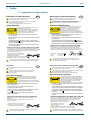
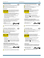
Installation Manual
Vega Video Router
96 and 192 port fully asymmetric Video Routers
snellgroup.com
Vega Video Router
Issue 2 Rev 1
www.snellgroup.com
Page 2
© 2013 Snell Limited
Vega Video Router
www.snellgroup.com
Contents
Contents
Contents . . . . . . . . . . . . . . . . . . . . . . . . . . . . . . . . . . . . . . . . . . . . . . . . . . . . . . . . . . . . . 3
Information and Notices . . . . . . . . . . . . . . . . . . . . . . . . . . . . . . . . . . . . . . . . . . . . . . . .
About this Manual . . . . . . . . . . . . . . . . . . . . . . . . . . . . . . . . . . . . . . . . . . . . . . . . . . . .
Customer Support . . . . . . . . . . . . . . . . . . . . . . . . . . . . . . . . . . . . . . . . . . . . . . . . . . . .
Copyright and Disclaimer . . . . . . . . . . . . . . . . . . . . . . . . . . . . . . . . . . . . . . . . . . . . . .
5
5
5
6
1. Safety. . . . . . . . . . . . . . . . . . . . . . . . . . . . . . . . . . . . . . . . . . . . . . . . . . . . . . . . . . . . . . 7
1.1 Explanation of Safety Symbols . . . . . . . . . . . . . . . . . . . . . . . . . . . . . . . . . . . . . . . 7
1.2 Mains Power Supplies. . . . . . . . . . . . . . . . . . . . . . . . . . . . . . . . . . . . . . . . . . . . . 10
1.2.1 Supplied Power Cord Color Code . . . . . . . . . . . . . . . . . . . . . . . . . . . . . 10
1.3 Lithium Batteries . . . . . . . . . . . . . . . . . . . . . . . . . . . . . . . . . . . . . . . . . . . . . . . . . 10
1.4 Rack Mounting . . . . . . . . . . . . . . . . . . . . . . . . . . . . . . . . . . . . . . . . . . . . . . . . . . .11
1.4.1 Vega 2U Router Rack Mounting. . . . . . . . . . . . . . . . . . . . . . . . . . . . . . . .11
1.4.2 Vega 4U Router Rack Mounting. . . . . . . . . . . . . . . . . . . . . . . . . . . . . . . .11
1.5 Laser Safety . . . . . . . . . . . . . . . . . . . . . . . . . . . . . . . . . . . . . . . . . . . . . . . . . . . . .11
1.6 Front Panel Lock . . . . . . . . . . . . . . . . . . . . . . . . . . . . . . . . . . . . . . . . . . . . . . . . . 12
1.7 Safety Standards . . . . . . . . . . . . . . . . . . . . . . . . . . . . . . . . . . . . . . . . . . . . . . . . . 13
1.8 EMC Standards . . . . . . . . . . . . . . . . . . . . . . . . . . . . . . . . . . . . . . . . . . . . . . . . . . 13
1.8.1 EMC Environment . . . . . . . . . . . . . . . . . . . . . . . . . . . . . . . . . . . . . . . . . 13
1.8.2 EMC Performance of Cables and Connectors . . . . . . . . . . . . . . . . . . . . 13
2. Installation . . . . . . . . . . . . . . . . . . . . . . . . . . . . . . . . . . . . . . . . . . . . . . . . . . . . . . . .
2.1 Ventilation . . . . . . . . . . . . . . . . . . . . . . . . . . . . . . . . . . . . . . . . . . . . . . . . . . . . . .
2.2 Dimensions . . . . . . . . . . . . . . . . . . . . . . . . . . . . . . . . . . . . . . . . . . . . . . . . . . . . .
2.2.1 Vega 2U Dimensions . . . . . . . . . . . . . . . . . . . . . . . . . . . . . . . . . . . . . . .
2.2.2 Vega 4U Dimensions . . . . . . . . . . . . . . . . . . . . . . . . . . . . . . . . . . . . . . .
2.3 Rack-mounting the Vega Router . . . . . . . . . . . . . . . . . . . . . . . . . . . . . . . . . . . . .
2.3.1 Shelf Mounting (2U and 4U Vega Routers) . . . . . . . . . . . . . . . . . . . . . .
2.3.2 Rack Slide Mounting (4U Vega Router Only). . . . . . . . . . . . . . . . . . . . .
2.4 Transit Brackets. . . . . . . . . . . . . . . . . . . . . . . . . . . . . . . . . . . . . . . . . . . . . . . . . .
2.5 Power and Fuses . . . . . . . . . . . . . . . . . . . . . . . . . . . . . . . . . . . . . . . . . . . . . . . .
2.5.1 Power Supply Replacement. . . . . . . . . . . . . . . . . . . . . . . . . . . . . . . . . .
2.6 Rear Fan Replacement . . . . . . . . . . . . . . . . . . . . . . . . . . . . . . . . . . . . . . . . . . . .
15
15
16
16
17
18
18
19
22
23
24
27
3. Specifications . . . . . . . . . . . . . . . . . . . . . . . . . . . . . . . . . . . . . . . . . . . . . . . . . . . . . . 29
Issue 2 Rev 1
Page 3
© 2013 Snell Limited
Vega Video Router
Issue 2 Rev 1
www.snellgroup.com
Page 4
Contents
© 2013 Snell Limited
Vega Video Router
www.snellgroup.com
Information and Notices
Information and Notices
About this Manual
This manual describes the installation of the Vega 2U and 4U Video Routers.
Refer to the Vega User Manual and the Vega Router Control manual for details on configuring
the router hardware and software panels.
If you have any questions regarding the installation and setup of your product, please refer to
the following Customer Service contact details.
Customer Support
United Kingdom (HQ)
+44 (0) 118 921 4214 (tel)
+44 (0) 118 921 4268 (fax)
[email protected]
Regional Support Contacts
Snell USA
+1 818 556 2616 (tel)
+1 818 556 2626 (fax)
[email protected]
Snell Germany
+49 (0) 6122 98 43 0 (tel)
+49 (0) 6122 98 43 44 (fax)
[email protected]
Snell Spain
+34 91 446 23 07 (tel)
+34 91 446 17 74 (fax)
[email protected]
Snell France
+33 1 41 95 30 50 (tel)
+33 1 41 95 30 51 (fax)
[email protected]
Snell Asia Pacific
+852 2356 1660 (tel)
+852 2575 1690 (fax)
[email protected]
Snell India
+91 124 462 6000 (tel)
+91 124 437 5888 (fax)
[email protected]
Snell Russia
+7 499 248 3443 (tel)
+7 499 248 1104 (fax)
[email protected]
Snell China
+86 10 6515 6158 (tel)
+86 10 6515 5659 (fax)
[email protected]
Customers with a support contract should call their personalized number, which can be found
in their contract, and be ready to provide their contract number and details.
Issue 2 Rev 1
Page 5
© 2013 Snell Limited
Vega Video Router
www.snellgroup.com
Information and Notices
Copyright and Disclaimer
Copyright protection claimed includes all forms and matters of copyrightable material and
information now allowed by statutory or judicial law or hereinafter granted, including without
limitation, material generated from the software programs which are displayed on the screen
such as icons, screen display looks etc.
Information in this manual and software are subject to change without notice and does not
represent a commitment on the part of Snell Limited. The software described in this manual is
furnished under a license agreement and can not be reproduced or copied in any manner
without prior agreement with Snell Limited. or their authorized agents.
Reproduction or disassembly of embedded computer programs or algorithms prohibited.
No part of this publication can be transmitted or reproduced in any form or by any means,
electronic or mechanical, including photocopy, recording or any information storage and
retrieval system, without permission being granted, in writing, by the publishers or their
authorized agents.
Snell operates a policy of continuous improvement and development. Snell reserves the right
to make changes and improvements to any of the products described in this document
without prior notice.
Issue 2 Rev 1
Page 6
© 2013 Snell Limited
Vega Video Router
www.snellgroup.com
Safety
1. Safety
1.1 Explanation of Safety Symbols
Explanation of Safety Symbols
!
Erklärung der Sicherheitssymbole
GB
This symbol refers the user to important information contained in
the accompanying literature. Refer to manual.
!
Dieses Symbol zeigt an, dass gefährliche Spannung vorhanden ist.
Es befinden sich keine vom Benutzer zu wartenden Teile im Geräteinneren.
Dieses Gerät sollte nur von geschultem Personal gewartet werden
This symbol indicates that hazardous voltages are present inside.
No user serviceable parts inside.
This unit should only be serviced by trained personnel.
Sicherheits-Warnhinweise
Safety Warnings
!
CAUTION
RISK OF ELECTRIC SHOCK
DO NOT REMOVE COVERS
NO USER SERVICEABLE PARTS
REFER SERVICING TO QUALIFIED
PERSONNEL ONLY
D
Dieses Symbol weist den Benutzer auf wichtige Informationen
hin, die in der begleitenden Dokumentation enthalten sind.
Servicing instructions where given, are for use by
qualified service personnel only.
To reduce risk of electric shock do not perform any
servicing other than that contained in the operating
instructions unless you are qualified to do so.
Refer all servicing to qualified personnel.
!
ACHTUNG
Gefahr von Elektroschocks.
Abdeckungen nicht entfernen
Keine vom Benutzer zu wartende Teile
Wenden Sie sich ausschließlich
an qualifiziertes Personal
Die angeführten Service-/Reparatur-Anweisungen sind
ausschließlich von qualifiziertem Service-Personal
auszuführen. Um das Risiko eines lektroschocks zu
reduzieren, führen Sie ausschließlich die im
Benutzerhandbuch eschriebenen Anweisungen aus,
es sei denn, Sie haben die entsprechende Qualifikation.
Wenden Sie sich in allen Service-Fragen an qualifiziertes Personal.
·
To reduce the risk of electric shock, do not expose this appliance
to rain or moisture.
·
Um das Risiko eines Elektroschocks zu reduzieren, setzen Sie das
Gerät weder Regen noch Feuchtigkeit aus.
·
Always ensure that the unit is properly earthed and power connections
correctly made.
·
Stellen Sie immer sicher, dass das Gerät ordnungsgemäß geerdet
und verkabelt ist.
·
This equipment must be supplied from a power system providing a
PROTECTIVE EARTH
connection and having a neutral connection
which can be reliably identified.
·
Dieses Equipment muss an eine Netzsteckdose mit
Schutzleiter
angeschlossen werden und einen zuverlässig identifizierbaren Nullleiter haben.
·
The power outlet supplying power to the unit should be close to the
unit and easily accessible
·
Die Netzsteckdose sollte nahe beim Gerät und einfach zugänglich sein.
Netzanschluss in anderen Ländern als der USA
Power connection in countries other than the USA
Das Equipment wird im Normalfall mit einem Netzkabel mit Standard IEC
Anschlussbuchse und einem Standard IEC Anschlussstecker geliefert.
Sollten Sie den angeschweißten Stecker auswechseln müssen, entsorgen
Sie diesen bitte umgehend. Die farbliche Belegung des Netzkabels ist wie folgt:
The equipment is normally shipped with a power cable with a standard IEC
moulded free socket on one end and a standard IEC moulded plug on the other.
If you are required to remove the moulded mains supply plug, dispose of the
plug immediately in a safe manner.
The colour code for the lead is as follows:
E
GREEN/YELLOW lead connected to E
L
(Protective Earth Conductor)
BLUE lead connected to N (Neutral Conductor)
BROWN lead connected to L (Live Conductor)
!
GRÜN GELB E = Schutzleiter
BLAU
N = Nulleiter
BRAUN
L = P = Phase
E
N
N
L
!
Caution If the unit has two mains supply inputs ensure that both power
cords are plugged into mains outlets operating from the same phase.
Légende :
!
E=
Schutzleiter
!
Ce symbole indique qu'il peut y avoir des tensions électriques
à l'intérieur de l'appareil. Ne pas intervenir sans l'agrément
du service qualifié.
!
N=
Nulleiter
L=
Phase
Achtung: Wenn das Gerät zwei Anschlussbuchsen hat, stellen
Sie bitte sicher, dass beide Netzkabel mit der selben Phase in die
Netzsteckdose gesteckt werden.
ESP
Éste símbolo refiere al usuario información importante contenida
en la literatura incluida. Referirse al manual.
Éste símbolo indica que voltajes peligrosos están presentes en el interior.
No hay elementos accesibles al usuario dentro.
Esta unidad sólo debería ser tratada por personal cualificado.
Advertencias de Seguridad
Précaution d'emploi :
RISQUE DE CHOC ELECTRIQUE
NE PAS RETIRER LE COUVERCLE
NE PAS INTERVENIR SANS
L'AGREMENT DU SERVICE
QUALIFIE
N=
Nulleiter
Explicación de los Símbolos de Seguridad
F
Ce symbole indique qu'il faut prêter attention et se référer
au manuel.
ATTENTION
L=
Phase
E=
Schutzleiter
Les procédures de maintenance ne concernent
que le service agréé. Afin de réduire le risque de
choc électrique, il est recommandé de se limiter
aux procédures d'utilisation, à moins d'en être qualifié.
Pour toute maintenance, contacter le service compétent.
RIESGO DE CHOQUE ELECTRICO
NO QUITAR LAS PROTECCIONNES
ELEMENTOS NO ACCESIBLES AL
USUARIO.
SERVICIO SOLAMENTE A PERSONAL
CUALIFICADO
Las instrucciones de servicio cuando sean dadas, son
sólo para uso de personal cualificado. Para reducir el
riesgo de choque eléctrico no llevar a cabo ninguna
operación de servicio aparte de las contenidas en las
instrucciones de operación, a menos que se esté
cualificado para realizarlas.
Referir todo el trabajo de servicio a personal cualificado.
· Pour réduire le risque de choc électrique, ne pas exposer l'appareil
dans un milieu humide.
·
Para reducir el riesgo de choque eléctrico, no exponer este equipo
a la lluvia o humedad.
· Toujours s'assurer que l'unité est correctement alimentée,
en particuliers à la liaison à la terre.
·
Siempre asegurarse de que la unidad está propiamente conectada a
tierra y que las conexiones de alimentación están hechas correctamente.
· La source électrique de cet équipement doit posséder une connexion
à la terre
, ainsi qu'une liaison « neutre » identifiable.
·
Este equipo debe ser alimentado desde un sistema de alimentación
con conexión a TIERRA
y teniendo una conexión neutra fácilmente
identificable.
·
La toma de alimentación para la unidad debe ser cercana y fácilmente
accesible.
· La prise électrique qui alimente l'appareil doit être proche
de celle-ci et accessible.
Câble secteur de pays autres que les Etats-Unis
Conexión de alimentación en otros países que no sean USA
L'équipement est livré avec un câble secteur au standard IEC, moulé
mâle/femelle.
Si vous souhaitez changr la prise mâle de votre cordon, voici les
codes couleurs des fils :
El equipo es normalmente entregado con un cable de alimentación con un
enchufe hembra estándar IEC en un extremo y con una clavija estándar
IEC en el otro. Si se requiere eliminar la clavija para sustituirla por otra,
disponer dicha clavija de una forma segura.
El código de color a emplear es como sigue:
E
E
Le fil VERT/JAUNE est connecté à T (Terre)
Le fil BLEU est connecté à N (Neutre)
Le fil MARRON est connecté à P (Phase)
!
T
P
VERDE/ AMARILLO conectado a E
L
N
(Conductor de protección a Tierra
Clavija
Aerea Macho
-Earth en el original-)
AZUL conectado a N (Conductor Neutro -Neutral en el original-)
MARRÓN conectado a L (Conductor Fase -Live en el original-)
T
N
N
Connecteur
P
Prise
Attention si l'appareil a 2 alimentations, s'assurer que les cordons
soient branchés sur la même phase.
Issue 2 Rev 1
!
Page 7
N
L
Enchufe
Aereo Hembra
Advertencia Si la unidad tuviera dos tomas de alimentación, asegurarse
de que ambos cables de alimentación están conectados a la misma fase.
© 2013 Snell Limited
Vega Video Router
www.snellgroup.com
Simboli di sicurezza:
!
Safety
Forklaring på sikkerhedssymboler
I
Questo simbolo indica l'informazione importante contenuta nei
manuali appartenenti all'apparecchiatura. Consultare il manuale.
!
Questo simbolo indica che all'interno dell'apparato sono presenti
tensioni pericolose. Non cercare di smontare l'unità.
Per qualsiasi tipo di intervento rivolgersi al personale qualificato.
Dette symbol indikerer farlig spænding inden i apparatet. Ingen bruger
servicerbare dele i apparatet på brugerniveau.
Dette apparat må kun serviceres af faglærte personer..
Attenzione:
!
ATTENZIONE
RISCHIO DI SHOCK ELETTRICO
NON CERCARE DI SMONTARE
L'UNITA PER QUALSIASI TIPO DI
INTERVENTO RIVOLGERSI AL
PERSONALE QUALIFICATO
DK
Dette symbol gør brugeren opmærksom på vigtig information
i den medfølgende manual.
Sikkerhedsadvarsler
Le istruzioni relative alla manutenzione sono ad uso
esclusivo del personale qualificato. E' proibito all'utente
eseguire qualsiasi operazione non esplicitamente
consentita nelle istruzioni. Per qualsiasi informazione
rivolgersi al personale qualificato.
!
FORSIGTIG !
RISIKO FOR ELEKTRISK STØD
DÆKPLADER MÅ IKKE FJERNES
INGEN BRUGER SERVICERBARE
DELE SERVICE MÅ KUN UDFØRES
AF FAGLÆRTE PERSONER
Serviceinstruktioner er kun til brug for faglærte
servicefolk. For at reducere risikoen for elektrisk
stød må bruger kun udføre anvisninger i
betjeningsmanualen.
Al service skal udføres af faglærte personer.
·
Per prevenire il pericolo di scosse elettriche è necessario non esporre
mai l'apparecchiatura alla pioggia o a qualsiasi tipo di umidità.
·
For at reducere risikoen for elektrisk stød må apparatet ikke
udsættes for regn eller fugt.
·
Assicurarsi sempre, che l'unità sia propriamente messa a terra e che
le connessioni elettriche siano eseguite correttamente.
·
Sørg altid for at apparatet er korrekt tilsluttet og jordet.
·
Questo dispositivo deve essere collegato ad un impianto elettrico
dotato di un sistema di messa a terra efficace.
·
Dette apparat skal forbindes til en nettilslutning, der yder
BESKYTTENDE JORD
og 0 forbindelse skal være tydeligt markeret.
·
La presa di corrente deve essere vicina all'apparecchio
e facilmente accessibile.
·
Stikkontakten, som forsyner apparatet, skal være tæt på apparatet
og let tilgængelig.
Connessione elettrica nei paesi diversi dagli Stati Uniti
Nettilslutning i andre lande end USA
Udstyret leveres normalt med et strømkabel med et standard IEC støbt løst
hunstik i den ene ende og et standard IEC støbt hanstik i den anden ende.
Hvis et af de støbte stik på strømkablet er defekt, skal det straks kasseres på
forsvarlig vis. Farvekoden for lederen er som følger:
L'apparecchiatura normalmente è spedita con cavo pressofuso con la presa
e spina standard IEC. Nel caso della rimozione della spina elettrica,
gettarla via immediatamente osservando tutte le precauzioni del caso.
La leggenda dei cavi è la seguente:
VERDE/GIALLO cavo connesso
ad "E" (terra)
BLU cavo connesso ad "N" (neutro)
MARRONE cavo connesso ad "L" ( fase)
!
E
L
N
N
Presa volante
L
Attenzione! Nel caso in cui l'apparecchio abbia due prese di corrente,
assicurarsi che i cavi non siano collegati a fasi diverse della rete elettrica.
·
F
Hun-stik
Turvamerkkien selitys
S
!
FI
Tämä merkki tarkoittaa, että laitteen mukana toimitettu kirjallinen
materiaali sisältää tärkeitä tietoja. Lue käyttöohje.
Tämä merkki ilmoittaa, että laitteen sisällä on vaarallisen voimakas jännite.
Sisäpuolella ei ole mitään osia, joita käyttäjä voisi itse huoltaa.
Huollon saa suorittaa vain alan ammattilainen.
Säkerhetsvarningar
CAUTION
0
Forsigtig Hvis enheden har to lysnetindgange, skal der sørges for at
begge ledninger tilsluttes lystnetudgange fra den samme fase.
!
Denna symbol hänvisar användaren till viktig information som
återfinns i litteraturen som medföljer. Se manualen.
RISK OF ELECTRIC SHOCK
DO NOT REMOVE COVERS
NO USER SERVICEABLE PARTS
REFER SERVICING TO QUALIFIED
PERSONNEL ONLY
J
0
Han-stik
Denna symbol indikerar att livsfarlig spänning finns på insidan.
Det finns inga servicevänliga delar inne i apparaten.
Denna apparat få endast repareras av utbildad personal.
!
J
F
Spina volante
Förklaring av Säkerhetssymboler
!
GRØN/GUL leder forbundet til J (Jord)
BLÅ leder forbundet til 0
BRUN leder forbundet til F(Fase)
E
Turvaohjeita
Serviceinstruktioner som anges avser endast kvalificerad
och utbildad servicepersonal. För att minska risken för
elektrisk stöt, utför ingen annan service än den som
återfinns i medföljande driftinstruktionerna, om du ej är
behörig. Överlåt all service till kvalificerad personal.
! VAROITUS
SÄHKÖISKUN VAARA ÄLÄ AVAA
LAITTEEN KANSIA EI SISÄLLÄ
KÄYTTÄJÄLLE HUOLLETTAVIA
OSIA HUOLTO AINOASTAAN
AMMATTILAISEN SUORITTAMANA
För att reducera risken för elektrisk stöt, utsätt inte apparaten för
regn eller fukt.
Huolto-ohjeet on tarkoitettu ainoastaan alan
ammattilaisille. Älä suorita laitteelle muita
toimenpiteitä, kuin mitä käyttöohjeissa on
neuvottu, ellet ole asiantuntija. Voit saada sähköiskun.
Jätä kaikki huoltotoimet ammattilaiselle.
·
Sähköiskujen välttämiseksi suojaa laite sateelta ja kosteudelta.
·
Se alltid till att apparaten är ordentligt jordad samt att strömtillförseln
är korrekt utförd.
·
Varmistu, että laite on asianmukaisesti maadoitettu ja että
sähkökytkennät on tehty oikein.
·
Denna apparat måste bli försörjd från ett strömsystem som är försedd
med jordadanslutning
samt ha en neutral anslutning som lätt identifierbar.
·
Laitteelle tehoa syöttävässä järjestelmässä tulee olla
SUOJAMAALIITÄNTÄ
ja nollaliitännän on oltava luotettavasti
tunnistettavissa.
·
Vägguttaget som strömförsörjer apparaten bör finnas i närheten samt
vara lätttillgänglig.
·
Sähköpistorasian tulee olla laitteen lähellä ja helposti tavoitettavissa.
Strömkontakter i länder utanför USA
Sähkökytkentä
Apparaten utrustas normalt med en strömkabel med standard IEC gjuten
honkontakt på ena änden samt en standard IEC gjuten hankontakt på den
andra änden. Om man måste avlägsna den gjutna hankontkaten, avyttra
denna kontakt omedelbart på ett säkert sätt. Färgkoden för ledningen är följande:
GRÖN/GUL ledning ansluten till E
(Skyddsjordad ledare)
E
L
BLÅ ledning ansluten till N (Neutral ledare)
BRUN ledning ansluten till L (Fas ledare)
!
Laitteen vakiovarusteena on sähköjohto, jonka toisessa päässä on muottiin
valettu, IEC-standardin mukainen liitäntärasia ja toisessa päässä muottiin
valettu, IEC-standardin mukainen pistoliitin. Jos pistoliitin tarvitsee poistaa,
se tulee hävittää heti turvallisella tavalla. Johtimet kytketään seuraavasti:
E
N
Stickkontakt-Hane
N
KELTA-VIHREÄ suojamaajohdin E-napaan
SININEN nollajohdin N-napaan
RUSKEA vaihejohdin L-napaan
L
Stickkontakt-Hona
E
N
Pistoliitin
Varning! Om enheten har två huvudsakliga elförsörjningar, säkerställ att
båda strömkablarna som är inkopplade i enheten arbetar från samma fas.
Issue 2 Rev 1
E
L
!
Page 8
N
L
Liitäntärasia
Huom! Jos laitteessa on kaksi verkkojännitteen tuloliitäntää, niiden johdot
on liitettävä verkkopistorasioihin, joissa on sama vaiheistus.
© 2013 Snell Limited
Vega Video Router
www.snellgroup.com
Símbolos de Segurança
!
Safety
P
O símbolo triangular adverte para a necessidade de consultar o
manual antes de utilizar o equipamento ou efectuar qualquer ajuste.
Este símbolo indica a presença de voltagens perigosas no interior
do equipamento. As peças ou partes existentes no interior do equipamento
não necessitam de intervenção, manutenção ou manuseamento por parte
do utilizador. Reparações ou outras intervenções devem ser efectuadas
apenas por técnicos devidamente habilitados.
Avisos de Segurança
As instruções de manutenção fornecidas são para
utilização de técnicos qualificados. Para reduzir o
risco de choque eléctrico, não devem ser realizadas
intervenções no equipamento não especificadas no
manual de instalações a menos que seja efectuadas
por técnicos habilitados.
·
Para reduzir o risco de choque eléctrico, não expor este equipamento
à chuva ou humidade.
·
Assegurar que a unidade está sempre devidamente ligada à terra e
que as ligações à alimentação estão correctas.
·
O sistema de alimentação do equipamento deve, por razões de
segurança, possuir ligação a terra de protecção
e ligação ao
NEUTRO devidamente identificada.
·
A tomada de energia à qual a unidade está ligada deve situar-se na
sua proximidade e facilmente acessível.
Ligação da alimentação noutros países que não os EUA
O equipamento é, normalmente, enviado com cabo de alimentação com ficha
IEC fêmea standard num extremo e uma ficha IEC macho standard no extremo
oposto. Se for necessário substituir ou alterar alguma destas fichas, deverá
remove-la e elimina-la imediatamente de maneira segura.
O código de cor para os condutores é o seguinte:
Condutor VERDE/AMARELO ligado a E (Terra) E
Condutor AZUL ligado a N (Neutro)
L
Condutor CASTANHO ligado a L (Vivo).
Ficha Livre
!
E
N
N
L
Tomada Livre
Atenção: Se a unidade tem duas fontes de alimentação assegurar que os
dois cabos de alimentação estão ligados a tomadas pertencentes à mesma fase.
Issue 2 Rev 1
Page 9
© 2013 Snell Limited
Vega Video Router
www.snellgroup.com
Safety
1.2 Mains Power Supplies
The Vega router has two IEC power sockets, one for the main and one for the redundant
power supply unit.
The mains Voltage will be auto detected provided it is in the range 100 - 240 Vac and
50 - 60 Hz.
•
Caution: Double Pole/Neutral Fusing.
•
This equipment has more than one power supply cord. To reduce the risk of
electrical shock, disconnect all the power supply cords before servicing.
•
Isolate the unit from other product outputs before servicing.
•
The IEC power inlets are the mains disconnection devices for this unit.
•
To reduce the risk of electric shock, plug each power supply cord into separate
branch circuits employing separate service grounds.
•
Ensure that all of the router modules and cards are correctly installed and firmly
seated before powering on the Vega router.
1.2.1 Supplied Power Cord Color Code
The equipment is shipped with a power cord with a standard molded IEC female plug on one
end and a standard mains plug on the other. If you are required to remove the molded mains
supply plug, dispose of the plug immediately in a safe manner. The color code for the cord is
as follows:
•
GREEN/YELLOW lead connected to E (Protective Earth Conductor)
•
BROWN lead connected to L (Live Conductor)
•
BLUE lead connected to N (Neutral Conductor)
1.3 Lithium Batteries
CAUTION
This equipment contains a lithium battery
There is a danger of explosion if this is replaced incorrectly
Replace only with the same or equivalent type.
Dispose of used batteries according to the manufacturers instructions.
Batteries shall only be replaced by trained service technicians
The Vega Video Routers contain a Lithium battery to provide non-volatile memory.
Issue 2 Rev 1
Page 10
© 2013 Snell Limited
Vega Video Router
www.snellgroup.com
Safety
1.4 Rack Mounting
Do not rack-mount the Vega 2U or 4U routers using only the front rack ears.
1.4.1 Vega 2U Router Rack Mounting
When rack-mounting the Vega router place the Vega router on a suitably specified and
installed rack shelf and secure the Vega router to the rack using the front ears.
1.4.2 Vega 4U Router Rack Mounting
The Vega 4U router can be mounted on a suitably specified and installed rack shelf and
secured in place using the rack ears. Alternatively it can be mounted on suitably specified and
installed rack rail slides.
1.5 Laser Safety
EN60825-1 (2001)
Safety of Laser Products
Issue 2 Rev 1
•
Caution: use of controls or adjustments or performance of procedures other than
those specified herein may result in hazardous radiation exposure. Viewing the
laser diode with the optical fiber removed and with the aid of optical magnifiers may
be hazardous.
•
This product is a Class 1 laser product (output power <15mW) at 1270 nm to
1610 nm with a beam divergence >30 mrad.
Page 11
© 2013 Snell Limited
Vega Video Router
www.snellgroup.com
Safety
1.6 Front Panel Lock
The Vega 2U and 4U routers are fitted with two captive screws (one on the left of the router
and one on the right, see Figure 1). These captive screws allow the router front panel to be
locked and in normal operation the router must remain locked.
Front Panel Fastening
Screw (1 of 2)
highlighted in red
Fig 1.
Important:
Issue 2 Rev 1
Front Panel Lock (Vega 2U shown)
•
The router must be locked in normal operation to ensure that it complies with safety
standards.
•
The risk of non-compliance is with the user if the router is left unlocked in normal
operation.
Page 12
© 2013 Snell Limited
Vega Video Router
www.snellgroup.com
Safety
1.7 Safety Standards
This equipment complies with the following standards:
EN60950-1: 2006
Safety of information Technology Equipment Including Electrical Business Equipment.
UL1419 (3rd Edition) - UL File E193966
Standard for Safety - Professional Video and Audio equipment
1.8 EMC Standards
This unit conforms to the following standards:
EN55103-1:2009 (Environment E4)
Electromagnetic Compatibility, Product family standard for audio, video, audio-visual and
entertainment lighting control apparatus for professional use. Part 1. Emission
EN55103-2:2009 (Environment E2)
Electromagnetic Compatibility, Product family standard for audio, video, audio-visual and
entertainment lighting control apparatus for professional use. Part 2. Immunity
Federal Communications Commission Rules, 47 CFR: 2009, Part 15, Subpart B (Class A)
1.8.1 EMC Environment
The product(s) described in this manual conform to the EMC requirements for, and are
intended for use in:
The controlled EMC environment (for example purpose-built broadcasting or recording
studios), and the rural outdoor environment (far away from railways, transmitters, overhead
power lines, etc.) E4
The applicable environment is stated in the Technical Profile section of the product operation
manual under “EMC Performance Information/Environment.”
1.8.2 EMC Performance of Cables and Connectors
Snell products are designed to meet or exceed the requirements of the appropriate European
EMC standards. In order to achieve this performance in real installations it is essential to use
cables and connectors with good EMC characteristics.
All signal connections (including remote control connections) shall be made with screened
cables terminated in connectors having a metal shell. The cable screen shall have a
large-area contact with the metal shell.
1.8.2.1
Coaxial Cables
Coaxial cable connections (particularly serial digital video connections) shall be made with
high-quality double-screened coaxial cables such as Belden 1694 or BBC type PSF1/2M.
1.8.2.2
D-type Connectors
D-type connectors shall have metal shells making good RF contact with the cable screen.
Connectors having “dimples” which improve the contact between the plug and socket shells
are recommended.
Issue 2 Rev 1
Page 13
© 2013 Snell Limited
Vega Video Router
Issue 2 Rev 1
www.snellgroup.com
Page 14
Safety
© 2013 Snell Limited
Vega Video Router
www.snellgroup.com
Installation
2. Installation
•
Refer to Section 1. Safety on page 7 before connecting power to the unit
•
The Installation and Maintenance of the Vega router and any associated
equipment must be carried out by persons suitably qualified to work with equipment
which may be connected to the mains supply.
•
The mounting and installation of the unit must be arranged by the user to comply
with all safety regulations of the indigenous authority.
2.1 Ventilation
The Vega 2U and 4U video routers have fans at the rear that pull air in through the front of the
unit and exhaust air out of the rear of the router. The power supplies are also fitted with fans
working in the same configuration.
Note:
Issue 2 Rev 1
•
For ventilation purposes, there must be a gap of at least 50 mm (2 inches) at the
front of the Vega routers and 100 mm (4 inches) a the rear of the routers.
•
Blocking the ventilation at the front or rear of the router will cause the router to
overheat and the router will fail.
•
The Vega router must be powered down if both rear fans fail.
•
If a power supply fan fails the Vega rear fans will increase in speed to compensate.
Page 15
© 2013 Snell Limited
Vega Video Router
www.snellgroup.com
Installation
2.2 Dimensions
2.2.1 Vega 2U Dimensions
Important:
•
For ventilation purposes, there must be a gap of at least 50 mm (2 inches) at the
front of the Vega router.
•
You must allow at least 100 mm (4 inches) of space at the rear of the router for
cables, connections and ventilation.
The Vega 2U router dimensions are as shown in Fig 2.:
Dimensions are in millimeters (inches)
Fig 2.
Issue 2 Rev 1
Vega 2U Router Dimensions
Page 16
© 2013 Snell Limited
Vega Video Router
www.snellgroup.com
Installation
2.2.2 Vega 4U Dimensions
Important:
•
For ventilation purposes, there must be a gap of at least 50 mm (2 inches) at the
front of the Vega router.
•
You must allow at least 100 mm (4 inches) of space at the rear of the router for
cables, connections and ventilation.
The Vega 4U router dimensions are as shown in Fig 3.:
Dimensions are in millimeters (inches)
Fig 3.
Issue 2 Rev 1
Vega 4U Router Dimensions
Page 17
© 2013 Snell Limited
Vega Video Router
www.snellgroup.com
Installation
2.3 Rack-mounting the Vega Router
The Vega 2U router must be shelf mounted in a standard 19” rack. The Vega 4U router can
either be mounted on rack slides or shelf mounted in a standard 19” rack. These mounting
methods are described in the following sections.
2.3.1 Shelf Mounting (2U and 4U Vega Routers)
•
Do not rack-mount the Vega router using only the front rack ears.
•
Make sure that sufficient space is available for the Vega router in the rack.
•
The Vega 2U router weighs 10 kg (22 lbs) for a full frame (without packaging).
When lifting the Vega 2U router into a 19" rack use the correct local Health and
Safety lifting guidelines.
•
The Vega 4U router weighs 18 kg (40 lbs) for a full frame (without packaging).
When lifting the Vega 4U router into a 19" rack use the correct local Health and
Safety lifting guidelines.
1.
Fig 4.
2.
Issue 2 Rev 1
Place the Vega router on a suitably specified and installed rack shelf.
Mounting the Vega Router in a 19” Rack
Use the correct rack mount screws or bolts to secure the router ears to the rack.
Page 18
© 2013 Snell Limited
Vega Video Router
www.snellgroup.com
Installation
2.3.2 Rack Slide Mounting (4U Vega Router Only)
•
Do not rack-mount the Vega router using only the front rack ears.
•
Make sure that sufficient space is available for the Vega router in the rack.
•
The Vega 4U router weighs 18 kg (40 lbs) for a full frame (without packaging).
When lifting the Vega 4U router into a 19" rack use the correct local Health and
Safety lifting guidelines.
The Vega 4U router can be mounted in a rack using rack slide rails allowing the router to be
slid forward in the rack for easy access.
Two lengths of slide rail are available from Snell:
•
VG-RKSL192-600 - Rack Mounting Slides, nominal rack depth 600 mm (23.5”)
•
VG-RKSL192-800 - Rack Mounting Slides, nominal rack depth 800 mm (31.5”)
The following instructions are only for use with the Snell rack mounting kits listed above.
Slide Bar Assembly
1.
Note:
•
The Chassis Mounting section of the slide has the lock release spring.
•
The Rack Mounting section of the slide has the ball bearing slide carrier.
2.
Important:
Separate the Chassis Mounting section of each slide from the Rack Mounting section
by operating the lock release spring.
Fit one of the Chassis Mounting sections to one side of the Vega router chassis
making sure that the lock release spring is towards the rear of the router (see
Figure 5). The fixing screws are supplied pre-fitted to the router (see important note).
•
The supplied screws must be used to avoid damaging the router.
•
The long rail kit only requires three of the six supplied screws, the unused screws
must be removed from the router and are not used.
•
The short rail kit only requires four of the six supplied screws, the unused screws
must be removed from the router and are not used.
Short Rail mounting kit
VG-RKSL192-600
Lock Release
Spring Position
Long Rail mounting kit
VG-RKSL192-800
Lock Release
Spring Position
Remove
unused Screws
Remove
unused Screws
4 x Screw
positions
Fig 5.
3.
Issue 2 Rev 1
3 x Screw
positions
Fitting Chassis Mounting Section
Repeat step 2. for the other side of the Vega router.
Page 19
© 2013 Snell Limited
Vega Video Router
www.snellgroup.com
Installation
Rack Mount Assembly
Long L Shaped
Rack Bracket
Offset
Threaded Bar
Offset
Threaded Bar
2 x Mounting
Bolts
2 x Cage
Nuts
2 x Mounting
Bolts
Short L Shaped
Rack Bracket
Rack Mounting
Section of the Slide,
Closed End Towards
Rear of Rack
2 x Cage Nuts
Fig 6.
Note:
Left Front and Rear Rack Uprights (Viewed from Front of Rack)
1.
Fit two cage nuts to the rear of the front upright of the rack.
2.
Fit the L shaped Short Rack Bracket by passing two mounting bolts through the cage
nuts through the bracket and into the offset threaded bar. The offset threaded bar
must be oriented for the minimum equipment width option.
3.
Repeat steps 1. and 2. for the second Short Front Bracket.
4.
Fit two cage nuts to the rear rail of the rack.
5.
Fit the long L shaped Rack Bracket by passing two mounting bolts through the cage
nuts through the bracket and into the offset threaded bar. The offset threaded bar
must be oriented for the minimum equipment width option.
6.
Repeat steps 4. and 5. for the second Long L shaped Rear Bracket.
7.
Fit the Rack Mounting section of the slide between the front and rear L shaped Rack
Brackets using four M4 bolts, washers and screws. The closed end of the Rack
Mounting section must be towards the rear of the rack, see Figure 6.
You may only be able to use one of the two pairs of holes in the front L shaped bracket as
the other pair may obscure one of the available holes in the rear L shaped bracket.
8.
Repeat step 7. for the second Rack Mounting section of the slide.
9.
Move the ball bearing carriers on each Rack Mounting section of the slide to the front
of the rack.
10. Line up both Rack Mounting sections with the front of the Chassis Mounting sections,
engage them and push gently home. The locking springs may click and lock as they
locate in the slides. If they lock release the locking springs and slide the router fully
into the rack.
Note:
Issue 2 Rev 1
Any misalignment of the router in the rack can be compensated for by partially releasing
the screws and operating the slide a number of times before retightening the screws.
Page 20
© 2013 Snell Limited
Vega Video Router
www.snellgroup.com
Installation
11. When you have confirmed correct slide operation check that all the screws are tight.
4 x Rack Bolts
Fig 7.
4U Vega Installed in Rack (Long Slide Kit Shown)
12. Fit the four rack bolts to secure the router rack ears to the rack, see Figure 7.
Issue 2 Rev 1
Page 21
© 2013 Snell Limited
Vega Video Router
www.snellgroup.com
Installation
2.4 Transit Brackets
There are two Transit Brackets in the Vega router that restrain the crosspoint and controller
cards during transit (see Figure 8). These transit brackets must be removed before the Vega
router is powered on.
1.
Loosen the captive front panel fastening screws on the left and right of the router
(see Figure 1 on page 12 for details).
2.
Open the front panel of the Vega router by pulling it outwards and swinging it down.
Vega Controller card Transit
Bracket screw x 1
Crosspoint card Transit
Bracket screws x 4
Vega 2U Router
Vega Controller/Buffer card
Transit Bracket screw x 1
Crosspoint card Transit
Bracket screws x 4
Vega 4U Router
Fig 8.
Issue 2 Rev 1
Vega 2U & 4U Router Transit Brackets
3.
Loosen but do not remove the four Crosspoint transit bracket screws and slide the
transit bracket to the right to remove it.
4.
Tighten the crosspoint transit bracket screws back up again and keep the bracket
somewhere safe in case the Vega router needs transporting in the future.
5.
Unscrew the Vega controller card transit bracket screw and remove the transit
bracket. Keep the bracket and screw with the crosspoint card transit bracket in case
the Vega router needs transporting in the future.
6.
Close the router front panel.
7.
Tighten the captive front panel fastening screws on the left and right of the router
(see Figure 1 on page page 12 for details) to lock the front panel.
8.
Refitting the transit brackets for transportation is the reverse of the removal process.
Page 22
© 2013 Snell Limited
Vega Video Router
www.snellgroup.com
Installation
2.5 Power and Fuses
The mains Voltage will be automatically detected provided it is in the range of 100 - 240 Vac
and 50 - 60 Hz. No voltage adjustment procedure is required.
•
Caution: Double Pole/Neutral Fusing.
•
Before connecting power to the router, refer to the safety warnings in section1.
•
Ensure that all of the router modules and cards are correctly installed and firmly
seated before powering on the Vega router.
Main (upper) and
Redundant (lower)
Power Supply Filtered
IEC Connectors.
Vega 2U Router
Main (upper) and
Redundant (lower)
Power Supply Filtered
IEC Connectors.
Vega 4U Router
Fig 9.
IEC Power Supply Connectors
Each IEC connector supplies an independent feed of power to each of the two power supply
modules as shown in Figure 10. The filtered IEC320 mains power connectors are suitable for
standard IEC power cables. The IEC power inlet is the mains disconnection device for this
unit.
There are two 15 A fast blowing fuse inside the power supply (one in the Live and one in the
Neutral line) that cannot be replaced by the user, see section 2.5.1 for details on removing a
power supply.
The router supports dual power supplies for redundancy. This is an option and so a second
PSU may not be fitted.
Issue 2 Rev 1
Page 23
© 2013 Snell Limited
Vega Video Router
www.snellgroup.com
Installation
Fig 10. IEC Power Supply Schematic (Main and Redundant PSUs fitted)
2.5.1 Power Supply Replacement
The Vega Video Routers can have up to two power supplies, a main and redundant in case of
PSU failure.
Power supplies can be safely hot-swapped without the need for the system to be powered
down (only if two power supplies are fitted and at least one is still working).
•
Caution: Double Pole/Neutral Fusing.
•
Once the failed PSU has been removed PSU redundancy will be lost until a new
PSU is fitted:
•
VG-PSU096-A - Vega 2U Replacement PSU part number
•
VG-PSU192-A - Vega 4U Replacement PSU part number
•
If a power supply fan fails the Vega rear fan will increase in speed to compensate.
•
The fan will continue to run for 10 to 20 seconds after the power supply is removed
from the router as 48 Vdc remains present for a short time.
1.
If a power supply or power supply fan fails on a Vega router the Status LEDs on the
left of the Vega front panel will indicate which has failed (Figure 11 and Table 1.).
PSU and Fan Status
LEDs
Front Panel Fastening
Screw (1 of 2)
Fig 11. PSU Status Indication (2U Vega shown)
Issue 2 Rev 1
Page 24
© 2013 Snell Limited
Vega Video Router
www.snellgroup.com
Status LEDs
PS1 LED
(upper PSU)
Fan
(upper PSU
Fan)
Installation
Function
•
Green = PSU 1 +48 Vdc output working
•
Off = PSU 1 not fitted
•
Red = PSU 1 +48 Vdc output not present
Possible Causes:
PSU 1 PSU board fuse(s) blown (Not user replaceable)
PSU 1 mains cable not connected
PSU 1 has failed
•
Green = Fan running**
•
Off = PSU 1 not fitted
•
Red = Failed
**Note: If the associated PSU has failed or has no mains input the fan will
still run from the common 48 Vdc output.
PS2 LED
(lower PSU)
Fan
(lower PSU
Fan)
•
Green = PSU 2 +48 Vdc Output Working
•
Off = PSU 2 not fitted
•
Red = PSU 2 +48 Vdc Output not present
Possible Causes:
PSU 2 PSU board fuse(s) blown (Not user replaceable)
PSU 2 mains cable not connected
PSU 2 has failed
•
Green = Fan running**
•
Off = PSU 2 not fitted
•
Red = Failed
**Note: If the associated PSU has failed or has no mains input the fan will
still run from the common 48 Vdc output.
Table 1.
Issue 2 Rev 1
Vega Status LEDs
Page 25
© 2013 Snell Limited
Vega Video Router
www.snellgroup.com
Installation
2.
Loosen the captive front panel fastening screws on the left and right of the router
(see Figure 11).
3.
Open the front panel of the Vega router by pulling it outwards and swinging it down.
Power Supply
retaining screws one
per Power Supply
Vega 2U
Vega 4U
Vega Power Supply
Fig 12. Vega 2U and 4U Router PSU Replacement
•
Caution: Double Pole/Neutral Fusing.
•
The fan will continue to run for 10 to 20 seconds after the power supply is removed
from the router as 48 Vdc remains present for a short time.
•
Once the Power Supply has been removed do not place your hands or any item
inside the space left by the power supply as mains voltages are present inside the
router.
4.
Unscrew the power supply retaining screw on the failed power supply (Figure 12).
5.
Slide the lock to the Right to release the failed power supply.
6.
Pull the failed power supply out of the Vega router while supporting the power supply
from underneath.
7.
Slide the replacement power supply into the Vega router and into the connectors at
the rear of the router.
8.
Slide the lock to the Left to lock the power supply into position.
9.
Tighten the power supply retaining screw.
10. The status LEDs for the replacement power supply should now turn Green to indicate
that the power supply is working correctly.
11. Close the router front panel.
12. Tighten the captive front panel fastening screws on the left and right of the router
(see Figure 11) to lock the front panel.
Issue 2 Rev 1
Page 26
© 2013 Snell Limited
Vega Video Router
www.snellgroup.com
Installation
2.6 Rear Fan Replacement
The Vega 2U router has two fans at the rear (one behind the other) and the Vega 4U router
has two fans at the rear (one above the other). For both routers the rear fans pull air in
through the front of the unit and exhaust the air out of the rear of the router. The power
supplies are also fitted with fans at the front working in the same configuration.
The rear fan assemblies can easily be replaced if required. If one fan fails in a fan assembly
the fan assembly should be replaced as soon as possible to maintain the redundancy of the
router.
Important:
•
1.
The rear fan assembly can be hot swapped but must be replaced within five
minutes to ensure the Vega router doesn’t overheat.
Before removing the fans read the following notes.
•
Caution: Double Pole/Neutral Fusing.
•
Ensure that you have a replacement rear fan assembly before removing the old fan
assembly.
Vega 2U Fan Module assembly replacement = VG-RMFU - Rear dual fan unit.
Vega 4U Fan Module assembly replacement = VG-RMFU192 - Rear fan unit.
•
2.
The fan blades can continue to spin for a short time after the fan assembly has
been removed from the router.
Remove the four fan retaining screws highlighted in red in Figure 13
Vega 2U Fan
retaining screws
Vega 2U
Vega 4U Fan
retaining screws
Vega port number
retaining plates
allow the removal
of the upper and
lower fans
Vega 4U
Fig 13. Vega 2U and 4U Router Rear Fans
Issue 2 Rev 1
Page 27
© 2013 Snell Limited
Vega Video Router
www.snellgroup.com
Installation
3.
Vega 4U only: remove the two port number retaining plates shown in Figure 13 to
free the fan assemblies.
4.
Pull the failed fan assembly straight back from the Vega router and support it from
underneath. The entire fan assembly will slide out.
Once the fan has been removed do not place your hands or any item inside the space left
by the fan as voltages are still present inside the router.
Issue 2 Rev 1
5.
Support the replacement fan assembly from underneath and slide it into the router.
6.
Ensure that the fan assembly is fully seated in the router. There should be no gap
between the Vega rear panel and the flange of the fan assembly.
7.
Vega 4U only: replace the two port number retaining plates shown in Figure 13.
8.
Screw the fan retaining screws into the router (see Figure 13).
9.
Check that the fans power up correctly. If the fans are not working repeat the fitting
process.
Page 28
© 2013 Snell Limited
Vega Video Router
www.snellgroup.com
Specifications
3. Specifications
Physical
Mounting height
Vega 2U: 2RU
Vega 4U: 4RU
Vega 2U: See page 16
Dimensions
Vega 4U: See page 17
Weight
Vega 2U: 10 kg (22 lb) maximum, fully loaded (all options)
Vega 4U: 18 kg (40 lb) maximum, fully loaded (all options)
Power
Connector
IEC (x 2 – dual redundant power supplies)
Voltage
100 to 240 Vac, 50 to 60 Hz
Vega 2U: 2.8 A max (8 A max inrush current)
Vega 4U: 4.5 A max (8 A max inrush current)
AC input power
Vega 2U: 230 W max. (Includes all redundancy options)
Vega 4U: 384 W max. (Includes all redundancy options)
Fusing
Two 15 A fast blowing fuses inside each power supply. One fuse
on the Live and one on the Neutral line.
The power supply is a sealed unit and the fuses are not user
replaceable.
Note:
•
Caution Double Pole/Neutral Fusing.
Environmental
Operating temp
5°C to 40°C
Maintained spec
0°C to 30°C
Storage temp
-20 to +80°C
Relative Humidity
5% to 95% non-condensing
Ventilation
Fan assisted. Front inlet, rear exhaust
Compliance
EMC - Emissions
EN55103-1 (EU), FCC Part 15 (USA)
EMC - Immunity
EN55103-2 (EU)
Safety
EN60950 (EU), UL1419 (USA)
Hazardous Material
RoHS-6 (UK) – Complies with EU Directive
Table 2.
Issue 2 Rev 1
Physical Specifications
Page 29
© 2013 Snell Limited
Vega Video Router
Issue 2 Rev 1
www.snellgroup.com
Page 30
Specifications
© 2013 Snell Limited