1
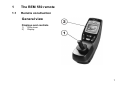
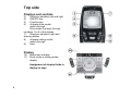
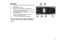
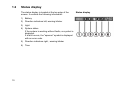
Yes, you can.® Invacare® REM 550 Remote User manual How can you get in touch with Invacare®? If you have any questions or need support, please contact your authorised Invacare® Dealer, who has the necessary know-how and equipment plus the special knowledge concerning your Invacare® product, and can offer you all-round satisfactory service. Should you wish to contact Invacare® directly, you can reach us in Europe at the following addresses and phone numbers. 2 Invacare Austria GmbH Herzog Odilostrasse 101 A-5310 Mondsee Austria : Fax: @: WWW: +43 6232 5 53 50 +43 6232 5 53 54 [email protected] www.invacare.at Invacare n.v. Autobaan 22 B-8210 Loppem (Brugge) Belgium : Fax: @: WWW: +32 (0)50 83 10 10 +32 (0)50 83 10 11 [email protected] www.invacare.be Invacare AG Benkenstraße 260 CH-4108 Witterswil Switzerland : Fax: @: WWW: +41 (0)61487 70 80 +41 (0)61487 70 81 [email protected] www.invacare.ch Invacare GmbH Alemannenstraße 10 88316 Isny Deutschland Fax @: WWW: +49 (0)7562 70 00 +49 (0)7562 7 00 66 [email protected] www.invacare.de Invacare A/S Sdr. Ringvej 37 DK-2605 Brøndby Danmark (Kundeservice): Fax (Kundeservice): @: WWW: Invacare® SA c/ Areny s/n Polígon Industrial de Celrà E-17460 Celrà (Girona) ESPAÑA : Fax: @: WWW: +45 (0)36 90 00 00 +45 (0)36 90 00 01 [email protected] www.invacare.dk +34 (0)972 49 32 00 +34 (0)972 49 32 20 [email protected] www.invacare.es Invacare® Poirier SAS Route de St Roch F-37230 Fondettes France : Fax: @: WWW: Invacare® Ltd Pencoed Technology Park Pencoed Bridgend CF35 5AQ United Kingdom (Customer services): Fax (Customer services): @: WWW: Invacare Mecc San s.r.l. Via dei Pini, 62 I - 36016 Thiene (VI) ITALIA : Fax: @: WWW: +39 0445 38 00 59 +39 0445 38 00 34 [email protected] www.invacare.it Invacare Ireland Ltd. Unit 5 Seatown Business Campus Seatown Rd, Swords County Dublin Ireland : Fax: @: WWW: +353 18 10 70 84 +353 18 10 70 85 [email protected] www.invacare.ie Invacare® AS Grensesvingen 9 Postboks 6230 Etterstad N-0603 Oslo Norge (Kundeservice): Fax (Kundeservice): @: @: WWW: +47 (0)22 57 95 00 +47 (0)22 57 95 01 [email protected] [email protected] www.invacare.no Invacare® B.V. Celsiusstraat 46 NL-6716 BZ Ede Nederland : Fax: @: @: WWW: +31 (0)318 69 57 57 +31 (0)318 69 57 58 [email protected] [email protected] www.invacare.nl : : Fax: @: WWW: +351 225 10 59 46 +351 225 10 59 47 +351 225 10 57 39 [email protected] www.invacare.pt Invacare Lda Rua Estrada Velha, 949 P-4465-784 Leça do Balio Portugal +33 (0)247 62 64 66 +33 (0)247 42 12 24 [email protected] www.invacare.fr +44 (0)1656 77 62 22 +44 (0)1656 77 62 20 [email protected] www.invacare.co.uk 3 Återförsäljare: Invacare® AB Fagerstagatan 9 S-163 91 Spånga Sverige (Kundtjänst): Fax (Kundtjänst): @: @: WWW: Tillverkare: Invacare® Deutschland GmbH Kleiststraße 49 D-32457 Porta Westfalica Deutschland MÖLNDAL : Fax: @: Eastern european countries 4 European Distributor Organisation (EDO) Kleiststraße 49 D-32457 Porta Westfalica Deutschland +46 (0)8 761 70 90 +46 (0)8 761 81 08 [email protected] [email protected] www.invacare.se +46 (0)31 86 36 00 +46 (0)31 86 36 06 [email protected] LANDSKRONA : Fax: @: +46 (0)418 2 85 40 +46 (0)418 1 80 89 [email protected] OSKARSHAMN : Fax: @: +46 (0)491 1 01 40 +46 (0)491 1 01 80 [email protected] Fax @: WWW: +49 (0)5731 75 45 40 +49 (0)5731 75 45 41 [email protected] www.invacare.de Table of Contents Chapter 1 Page The REM 550 remote 1.1 1.2 1.3 1.4 1.5 1.6 1.7 1.8 1.9 1.10 7 Remote construction.................................................................................................................7 Status display ..........................................................................................................................10 1.2.1 Battery charge display ..................................................................................................11 1.2.2 Battery alarms...............................................................................................................12 1.2.3 System status ...............................................................................................................12 Using Buddy Buttons with the remote ..................................................................................13 Steering the wheelchair with the remote ..............................................................................14 1.4.1 How to find out which steering gear your wheelchair has ............................................16 1.4.2 How a wheelchair with "Indirect Steering" reacts to joystick movements.....................17 1.4.3 How a wheelchair with "Direct Steering" reacts to joystick movements. ......................18 Switching the wheelchair off ..................................................................................................19 Locking/unlocking the wheelchair.........................................................................................20 1.6.1 Locking the wheelchair .................................................................................................20 1.6.2 Unlocking the wheelchair..............................................................................................21 Switching the lights on and off ..............................................................................................22 Switching the warning blinker on and off .............................................................................23 Operating the electrical adjustment options ........................................................................24 1.9.1 Which symbols are displayed and what they mean .....................................................24 1.9.2 Activate adjustment mode ............................................................................................25 1.9.3 Selecting and actuating adjustment options .................................................................26 1.9.4 Changing from setting mode to drive mode..................................................................27 Further adjustment options....................................................................................................28 1.10.1 Deactivating programming mode..................................................................................28 1.10.2 Changing the screen brightness...................................................................................29 5 1.11 6 1.10.3 Setting the time.............................................................................................................30 1.10.4 Display/hide time display ..............................................................................................31 1.10.5 Changing the screen background.................................................................................32 Error diagnosis ........................................................................................................................32 1.11.1 Error codes and diagnosis codes .................................................................................34 1 The REM 550 remote 1.1 Remote construction General view Displays and controls 1) 2) Drive lever Display 7 Top side Displays and controls 3) 4) 5) 6) Direction indicators left and light ON/OFF key Function key Activate drive mode/ switch-through Drive mode is shown through numbers 1 to 5 in the display. 7) Direction indicators right and warning blinker 8) Activate setting mode/ switch-through 9) Horn Display 10) 11) Status bar indicator Drive mode or setting mode display Assignment of display fields in display to keys. 8 Bottom 1) 2) 3) 4) 5) 4) Socket for charging cable and for programming the remote Socket for bus cable Socket I for Buddy Button (corresponds to "Activate drive mode/switch-through" key). This key is deactivated as standard. ON/OFF socket for Buddy Button (corresponds to "ON/OFF" key) Socket II for Buddy Button (corresponds to "Activate setting mode" key). This key is deactivated as standard. The cover cap must be removed if sockets 2 to 5 are to be used. To do this, remove the Phillips screw. 9 1.2 Status display The status display is located at the top edge of the screen. It contains the following information: 1) Battery 2) Direction indicators left, warning blinker 3) Light 4) System status If the system is working without faults, no symbol is displayed. If a fault occurs, the "spanner" symbol is displayed with an error code. 5) Direction indicators right , warning blinker 6) Time 10 Status display 1.2.1 Battery charge display The battery charging status is shown in the screen status display. • The battery symbol illuminates green (5 bars): Maximum driving range! • The battery symbol illuminates yellow (4 bars): Decreased driving range! • The battery symbol illuminates yellow (3 bars): Decreased driving range! Please charge the batteries. • The battery symbol illuminates red (2 bars): Low driving range! Please charge the batteries as soon as possible. • The battery symbol illuminates red (1 bar): Very low driving range! Please charge the batteries immediately. • The battery symbol illuminates red (no bars): Driving range exhausted! Charge the batteries immediately. NOTE To protect against total battery discharge, the electronics system automatically switches the drive to battery reserve after a specified driving time, and the wheelchair will come to a standstill. 11 1.2.2 Battery alarms Alarms concerning the battery charging status are displayed in the centre of the screen. 1.2.3 • The battery symbol illuminates red (completely full): The batteries are overcharged! - Disconnect the battery charger. - Switch the lights on. • The battery symbol illuminates red and is crossed out: The batteries are empty! - Switch the wheelchair off. - Charge the batteries immediately. System status The system status is shown in the middle of the status display if a fault occurs. An error code is displayed to the right of the "spanner" symbol. You can use this error code to help find the cause of the fault as described in Chapter 1.11. 12 1.3 Using Buddy Buttons with the remote What is a Buddy Button? A Buddy Button (4) is an additional button which can be used to activate remote functions. The sockets for Buddy Buttons are located underneath the remote. 1) Socket I (corresponds to "Activate drive mode/switchthrough" key) The button is deactivated as standard. 2) ON/OFF socket (corresponds to "ON/OFF" key) 3) Socket II (corresponds to "Activate setting mode" key) The button is deactivated as standard. 4) Buddy Button The cover cap must be removed if sockets 1 to 3 are to be used. To do this, remove the Phillips screw. 13 1.4 Steering the wheelchair with the remote • Press the "ON/OFF" key. • The display illuminates. • The mode display (A) shows the drive level. • The wheelchair is ready to drive. • You can set the drive levels using the drive mode key (C). In this case, drive level 1 is the slowest and drive level 5 the fastest setting. • Within each drive level you can carry out fine settings for the speed using the function key (B). The fine settings are displayed in the ring (D). This enables, for example, adapting the speed to that of an attendant. Information for mobility devices with G-Trac™ If your mobility device has been fitted with the G-Trac™ option you will NOT be able to change driving profiles while travelling. 14 The G-Trac™ option If your mobility device has been fitted with the G-Trac™ option, it will enable you to enjoy fatiguefree and safer driving. • G-Trac™ supports you in staying at the same driving speed and travel direction, and therefore reduces fatigue. • It improves the tracking and therefore increases the user's driving comfort. • G-Trac™ stabilises the mobility device tracking in the case of front-wheel-drive devices and finds the optimum driving speed for travelling round bends. This prevents skidding, slipping or tipping of the mobility device and therefore increases safety. Can the electronic system programming be adapted? The electronic controller is programmed with standard values during manufacture. Your Invacare® dealer can carry out programming tailored to fit your requirements. WARNING: Any alteration to the drive programme can influence vehicle handling and the tipping stability of the electric vehicle! • Alterations to the drive programme may only be carried out by trained Invacare® dealers! • Invacare® supplies all electric vehicles from the factory with a standard drive programme. Invacare® can only assume a warranty for the safe vehicle handling of the electric vehicle – in particular tipping stability - for this standard drive programme! Is the wheelchair not ready to go after switching on? Check the status display (see Chapter 1.2.3). If an error code is shown on the status display, you can recognise and rectify the fault with the help of Chapter Fehler! Verweisquelle konnte nicht gefunden werden.. 15 1.4.1 How to find out which steering gear your wheelchair has In the case of a wheelchair with indirect steering, control takes place via the separate drive wheel controller. Indirect steering is used for wheelchairs with front wheel, rear wheel and central drive. In the case of a wheelchair with direct steering, control takes place via a servo motor. The controller for a wheelchair with indirect and direct steering is described below. 16 1.4.2 How a wheelchair with "Indirect Steering" reacts to joystick movements. "Indirect Steering" occurs by individually applying power to the drive wheels, and is found on wheelchairs with front, rear and middle wheel drive. Travel direction The further the joystick is moved in a particular direction, the more dynamically the wheelchair reacts. Note: To brake quickly, simply let go of the joystick. It will then automatically return to the middle position. The wheelchair will brake. 17 1.4.3 How a wheelchair with "Direct Steering" reacts to joystick movements. Steering is operated by means of a servo motor. Travel direction The further the joystick is moved in a particular direction, the more dynamically the wheelchair reacts. Note: To brake quickly, simply let go of the joystick. It will then automatically return to the middle position. The wheelchair will brake. 18 1.5 Switching the wheelchair off • Press the "ON/OFF" key (1). • The remote switches off. NOTE: If you press the "ON/OFF" key while driving, an emergency stop is carried out. The remote only switches off after this. 19 1.6 Locking/unlocking the wheelchair 1.6.1 Locking the wheelchair 20 • Press the "ON/OFF" key (1) for more than 4 seconds. • A lock is shown in the display and the remote switches itself off. 1.6.2 Unlocking the wheelchair • Press the "ON/1OFF" key (1). • Press the horn (2) twice within 10 seconds. • The display illuminates. • The mode display (A) shows the drive level. • The wheelchair is ready to drive. 21 1.7 22 Switching the lights on and off • Press the direction indicator left key (1) for more than 5 seconds. • The light is then switched on or off. 1.8 Switching the warning blinker on and off • Press the direction indicator right key (1) for more than 5 seconds. • The warning blinkers are switched on or off. 23 1.9 Operating the electrical adjustment options Electrical adjustment options, such as electrical legrests or an electrical backrest, are carried out as described below. 1.9.1 Which symbols are displayed and what they mean Not every wheelchair has all the options. Only the symbols for functions which the wheelchair actually has available are displayed. 24 Seat tilt Seat lifter Backrest angle Both leg supports Left-hand legrest Verticalizer Right-hand legrest Seat tilting with centre of gravity displacement 1.9.2 Activate adjustment mode • Press the "Activate setting mode" key (A) next to the wheelchair symbol. • The wheelchair changes to setting mode. • The mode display (B) changes to a wheelchair symbol. 25 1.9.3 Selecting and actuating adjustment options • Press the function key (C) under the wheelchair symbol or move the drive lever left or right several times until the required adjustment option is shown in the display. • The corresponding adjustment option (e.g. seat tilting) is shown in blue on the display. • Press the drive lever to the front or rear to activate the actuator motor. NOTE: The distance you press the drive lever determines the dynamics of the movement. If you only press the drive lever a little, the actuator motor will only move slowly. If you press the drive lever as far as you can, the actuator motor will move faster. 26 1.9.4 Changing from setting mode to drive mode • Press the "Activate drive mode/switch-through" key (D). • The remote will switch back to drive mode. • The mode display (A) shows the drive level. 27 1.10 Further adjustment options 1.10.1 Deactivating programming mode The setting options described here are standard settings. The functions of the buttons can be allocated differently, specific to the customer, or can be deactivated. • Press the "Activate setting mode" key (A) next to the P symbol. • Press the function key (B) or move the drive lever right or left until the required adjustment option is shown in the display. • Press the drive lever forward to confirm the required adjustment option. You can change the following settings. Screen brightness 28 Time Clock display Screen background 1.10.2 Changing the screen brightness • The symbol for screen brightness (see Chapter 1.10.1) is shown in the display. • Press the function key (B) or move the drive lever right or left to change the screen brightness. • The bar underneath the sun symbol shows the adjusted value. • Press the "Activate setting mode" key (A) or move the drive lever right or left to confirm the required setting options. • To carry out further settings, press the "Activate setting mode" key (A) or move the drive lever right or left again. • To return to drive mode, press the "Activate drive mode/switch-through" key (C). 29 1.10.3 Setting the time 30 • The symbol for time (see Chapter 1.10.1) is shown in the display. • Press the function key (B) or move the drive lever right or left to select the individual digits in the time display. • The digit to be changed is shown blinking. • Move the drive lever forwards to change the individual digits in the time display. • Move the drive lever to the rear to save the changed time. • To carry out further settings, press the "Activate setting mode" key (A) or move the drive lever right or left again. • To return to drive mode, press the "Activate drive mode/switch-through" key (C). 1.10.4 Display/hide time display • The symbol for time display (see Chapter 1.10.1) is shown in the display. • If the green symbol is shown in the display, the time display is available. • If the red symbol is shown in the display, the time display is hidden. • Press the drive lever to the right or left to display or hide the time display. • If you press the drive lever forwards when two ticks are displayed above the function key (B), the changes you have made to the time display will be saved. • If you press the drive lever forwards when two crosses are displayed above the function key (B), the changes you have made to the time display will not be saved. • To carry out further settings, press the "Activate setting mode" key (A) or move the drive lever right or left again. • To return to drive mode, press the "Activate drive mode/switch-through" key (C). 31 1.10.5 Changing the screen background • The symbol for screen background (see Chapter 1.10.1) is shown in the display. • Press the function key (B) or move the drive lever right or left to select one of the three modes. • Select (1) if you want to have a black screen background. • Select (2) if you want to have a white screen background. • Select (3) if you want the screen background to be set to standard. • Press the "Activate setting mode" key (A) or move the drive lever forwards to save the change. • To carry out further settings, press the "Activate setting mode" key (A) or move the drive lever right or left again. • To return to drive mode, press the "Activate drive mode/switch-through" key (C) NOTE: The Automatic screen background setting is standard on delivery. When the lighting is switched on, the background will change from white to black. 1.11 Error diagnosis If the electronic system shows a fault, please use the following fault-finding guide to locate the fault. 32 NOTE Ensure that the drive electronics system is switched on before starting any diagnosis. If the status display is OFF: Check whether the drive electronics system is SWITCHED ON. Check whether all cables are correctly connected. Ensure that the batteries are not discharged. If a fault number is displayed in the status display: Please proceed to the next section. 33 1.11.1 Error codes and diagnosis codes The drive electronics system is able to correct some errors automatically. In this case, the code number in the status display will disappear. To do this switch the remote on and off several times. Wait approx. 5 seconds each time before switching the remote on again. If the error is not corrected by this process, localise the error using the code numbers listed below. CODE NUMBER 1 2 3 4 34 FAULT IMMEDIATE MEASURE FURTHER HELP Module defective. Seat not at driving height • • - Contact your dealer. Accessory error Fault in left-hand motor. Connection loose/defective or motor defective. • Check connecting plugs. • • Contact your dealer. Contact your dealer Fault in right-hand motor. Connection loose/defective or motor defective. • Check connecting plugs. • Contact your dealer If the lifter is raised, lower it in stages until the status display goes out. If the lifter is lowered too far, raise the lifter in stages until the status display goes out. Only drive when the seat is at driving height! CODE NUMBER FAULT Fault/brake fault on left-hand motor. Connection loose/defective or motor defective.. Left-hand motor disengaged (in the case of GB motors) Both motors disengaged (in the case of standard motors) Fault/brake fault on 6 right-hand motor. Connection loose/defective or motor defective. Right-hand motor disengaged (in the case of GB motors) Discharged battery. 7 Battery voltage too 8 high. 9 oder 10 Incorrect data transmission between modules. 5 IMMEDIATE MEASURE FURTHER HELP • Check connecting plugs. • • Engage motor turn the remote on and off. - • Engage motors turn the remote on and off. - • Check connecting plugs. • • Engage motor turn the remote on and off - • - Charge battery • • Contact your dealer Contact your dealer • Contact your dealer - Contact your dealer Contact your dealer 35 CODE NUMBER 11 FAULT IMMEDIATE MEASURE Motors overloaded. • • • 12 36 Compatibility problems between modules. - FURTHER HELP Switch off the remote, wait • a few minutes and then switch it on again. Check wheels. These should not be obstructed. Select a driving route with less gradients. • Contact your dealer Contact your dealer 37 English Order No. of this Manual: 1528090.DOC Release Date: 2012-03-30