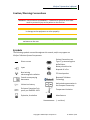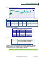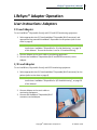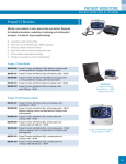
1
LifeSync® System User’s Manual 0086 LifeSync Corporation One East Broward Boulevard Suite 1701 Fort Lauderdale, Florida 33301 U.S.A. Copyright© 2008 LifeSync Corporation All rights reserved. No part of this manual may be reproduced, photocopied or transmitted without the express written consent of LifeSync Corporation. LifeSync® and LeadWear® are trademarks of LifeSync Corporation. Bluetooth® is a trademark owned by Bluetooth SIG, Inc., USA and licensed to LifeSync Corporation. www.LifeSyncCorp.com Table of Contents Preface ................................................................................................................................ 1 Introduction .................................................................................................................... 1 Indications for Use ...................................................................................................... 1 Contraindications........................................................................................................ 1 Intended Use of LifeSync® Wireless System............................................................... 1 Caution/Warning Conventions ................................................................................... 2 Symbols ....................................................................................................................... 2 Safety Information .......................................................................................................... 3 Warnings ..................................................................................................................... 3 Cautions ...................................................................................................................... 5 Notes ........................................................................................................................... 6 Introduction to the LifeSync® Wireless System .................................................................. 7 System Overview ............................................................................................................ 7 Unpacking Checklist ........................................................................................................ 8 Patient Transceiver ..................................................................................................... 8 Monitor Transceiver ................................................................................................... 8 LeadWear® Disposable ............................................................................................... 8 System Components ....................................................................................................... 9 LeadWear® Disposable .............................................................................................. 9 3/5 Lead LeadWear® Disposable ........................................................................... 9 Precordial Lead LeadWear® Disposable............................................................... 10 12 Lead LeadWear® Disposable ........................................................................... 10 Patient Transceiver ................................................................................................... 11 Monitor Transceiver ................................................................................................. 12 Smart Battery ............................................................................................................ 13 Token......................................................................................................................... 14 Power Supply ............................................................................................................ 14 Accessories.................................................................................................................... 15 Patient Transceiver Pouch ........................................................................................ 15 Armband ................................................................................................................... 15 Introduction to the LifeSync® Adapter………………………………………………………………………….16 LifeSync® Wireless System Operation .............................................................................. 17 Wireless System Set Up ................................................................................................ 17 Install/Check Smart Batteries in Transceivers .......................................................... 17 Mount the LifeSync® Monitor Transceiver .............................................................. 18 User Instructions: Wireless Monitoring........................................................................ 19 3/5 Lead Wireless Monitoring .................................................................................. 19 12 Lead Wireless Monitoring.................................................................................... 21 Temporary ECG ......................................................................................................... 22 Patient Transfer: Wireless to Wireless ..................................................................... 26 i System Removal........................................................................................................ 27 Smart Batteries ......................................................................................................... 27 Respiration ................................................................................................................ 29 User Instructions: LeadWear® Disposable.................................................................... 30 3/5 Lead Monitoring ................................................................................................. 30 12 Lead Monitoring................................................................................................... 32 LifeSync® Adapter Operation............................................................................................ 33 User Instructions: Adapters .......................................................................................... 34 12 Lead Adapter and 3/5 Lead Adapter.................................................................... 34 Patient Transfer: Wireless to Adapter ...................................................................... 35 Maintenance & Troubleshooting...................................................................................... 36 System Functional Check .............................................................................................. 36 Required Equipment ................................................................................................. 36 Smart Batteries Preparation. .................................................................................... 36 Monitor Transceiver Set Up/Power on Test/Battery Charger.................................. 37 Patient Transceiver Set Up/Power on Test............................................................... 37 Transceiver Synchronizing – Single Permanent........................................................ 37 Monitor Transceiver Set Up – Temporary 12 Lead................................................... 38 Transceiver Synchronizing – Temporary 12 Lead ..................................................... 38 Transceiver – Confirm Low Battery Charge Indicators on Patient Transceiver........ 39 Smart Battery ................................................................................................................ 40 Battery Life................................................................................................................ 40 Battery Storage ......................................................................................................... 40 Adapter Maintenance ................................................................................................... 41 Cleaning LifeSync® System Components ...................................................................... 42 Cleaning the Transceiver, Battery and Power Supply............................................... 42 Cleaning, Disinfecting and Sterilizing the Adapters.................................................. 42 Cleaning the LeadWear® Disposables....................................................................... 43 Troubleshooting............................................................................................................ 44 Patient Transceiver won’t turn On ........................................................................... 44 Monitor Transceiver won’t turn On.......................................................................... 44 Patient Transceiver Intermittent On/Off .................................................................. 44 Monitor Transceiver Intermittent On/Off ................................................................ 45 Transceivers Red Service Light On ............................................................................ 45 All LEDs On ................................................................................................................ 45 No or Intermittent Communication “synch” between Transceivers........................ 45 Patient Transceiver beeping ..................................................................................... 46 Monitor Transceiver beeping.................................................................................... 46 Patient Transceiver All LEDs Intermittent On/Off .................................................... 46 Monitor Transceiver All LEDs Intermittent On/Off................................................... 46 Battery does not last 24 hours on Patient Transceiver or 12 hours on Monitor Transceiver................................................................................................................ 47 Monitor Transceiver not charging battery, or Monitor Transceiver battery charge indicator not lit ......................................................................................................... 47 ii V Lead Off (for 3/5 Lead only)................................................................................... 47 No ECG or Leads Off.................................................................................................. 47 Inverted signal on ECG equipment ........................................................................... 48 Intermittent ECG, Artifact and Noise........................................................................ 48 No, Intermittent or Noise Respiration ...................................................................... 49 Adapter No ECG or Respiration ................................................................................ 50 Adapter Intermittent, Noisy ECG or Respiration ...................................................... 51 Technical / Specifications.................................................................................................. 44 Specifications ................................................................................................................ 44 Manufacturer’s Information ......................................................................................... 61 Reorder Information ..................................................................................................... 61 iii LifeSync® System User’s Manual 1 Preface Preface Introduction Indications for Use The LifeSync® Wireless System is indicated for use when ECG monitoring is needed and a wireless cable‐free connection is desired between the patient and the ECG monitor. The LifeSync® Wireless System will also transmit the patient respiration waveform for those ECG systems that include a respiration function. Contraindications The use of the LifeSync® Wireless System is contraindicated: • When ECG monitor output may be used to perform a synchronized cardioversion or intracardiac monitoring • When using an internal monitoring device synchronized to an external device; i.e. in electrophysiology • During use of MRI or PET scan equipment • When performing external pacing Intended Use of LifeSync® Wireless System The LifeSync® Wireless System is intended for use as a radio‐frequency signal transmitter and receiver of patient electrocardiograph (ECG) signals which are displayed on the ECG monitors of various manufacturers’ ECG systems. It can be used by clinicians to facilitate ECG monitoring of ambulatory and non‐ambulatory adult patients in health care facilities by removing the conventional cable connection between the patient and the ECG monitor. CAUTION: United States Federal law restricts this device to sale, distribution or use by, or on the order of, a licensed medical practitioner. This User Manual is intended for use by trained clinicians, who are presumed to be familiar with the use of ECG monitoring equipment, and interpretation of vital signs collected and displayed by that equipment. The LifeSync® Adapter is intended to be used in conjunction with various patient monitoring equipment such as ECG and EKG. Copyright© 2008 LifeSync Corporation LS‐164 Rev 7/08 LifeSync® System User’s Manual 2 Preface Caution/Warning Conventions WARNING: Calls attention to WARNINGS – conditions or practices that could result in personal injury to the patient or the clinician. CAUTION: Calls attention to CAUTIONS – conditions or practices that could result in damage to the equipment or other property. NOTE: Calls attention to NOTES – information of particular importance or assistance to the user. Symbols The following symbols are used throughout this manual, and/or may appear on LifeSync® Wireless System Components: Patient Connections are Direct current Type CF, protected against defibrillation Battery should not be Input disposed of in fire Non‐ionizing electromagnetic radiation ETL listed product Consult accompanying documents Bluetooth® Wireless Technology Lithium ion battery Enclosure Protection Drip proof: per EN60529: 1991 Expiration, Use before Authorised representative in the European Community Temperature limitation Manufacturer Xxxxxxxxxxxxxx (… serial no.) Copyright© 2008 LifeSync Corporation LS‐164 Rev 7/08 LifeSync® System User’s Manual 3 Preface Safety Information Warnings Explosion Hazard – In accordance with UL 60601‐1, which applies to all medical equipment, do not use this device in the presence of flammable anesthetics. In order for the LifeSync® LeadWear® Disposable to work properly, the RL / Right Leg / GREEN electrode must be connected to the patient at all times with appropriate electrode attached. Follow electrode manufacturer’s guidelines for skin prep prior to placing electrodes on patient. LifeSync® LeadWear® Disposable is radiolucent. Using some digital imaging systems, it may be less apparent that LeadWear® Disposable and radiolucent electrodes are outside the body. When attached to LeadWear® Disposable snaps, electrodes with opaque posts provide a better indication that LeadWear® Disposable snaps and electrodes are outside the body. To ensure patient safety, only LifeSync® LeadWear® Disposable products should be used with the LifeSync® Patient Transceiver. The safety of connecting other devices, leads or cables to the Patient Transceiver has not been evaluated and may present safety hazards. Furthermore, substandard performance may result from the use of incompatible components. The LifeSync® Monitor Transceiver should only be connected to patient monitors as illustrated in the System Set Up section of this manual, and only to those monitors that have been validated for compatibility with the LifeSync® Wireless System. Refer to the Cautions section of this manual for a list of validated monitors, or contact LifeSync Corporation for the most current list of validated monitors. Only use the approved LifeSync® Power Supply (Model LS‐132) in order to ensure that the Patient Monitor (to which the LifeSync® Monitor Transceiver is connected) continues to comply with risk (leakage) current, and EMI/EMC requirements. Normal operation of the LifeSync® Wireless System should be verified in the configuration in which it will be used before engaging in use with a patient. Inspect and test the LifeSync® Transceivers, smart batteries, and power supply frequently. Do not operate the LifeSync® Wireless System if any system component appears damaged or appears not to function properly. See System Functional Check section of this manual for procedure to verify normal operation. If either of the LifeSync® Transceivers detects an unrecoverable fault, the RED Service LED will illuminate continuously, indicating that service is required prior to use of the LifeSync® Transceiver. Do not attempt to use a LifeSync® Copyright© 2008 LifeSync Corporation LS‐164 Rev 7/08 LifeSync® System User’s Manual 4 Preface Transceiver that indicates service is required. When RED service LED is on, the LifeSync® Wireless System will stop working. The LifeSync® Wireless System can remain applied to a patient during defibrillation. The ECG signal will be interrupted for no more than a few seconds during defibrillation. The LifeSync® Wireless System should not be used to perform a synchronized cardioversion, due to signal latency in the radio transmission. The LifeSync® Wireless System can be used during procedures using electrosurgery machines. However, even though the LifeSync® Transceivers contain electrosurgical interference suppression filters, increased noise will likely be present while an electrosurgery device is in use. Location of the electrosurgery return pad is very important to minimize interference (be sure to follow electrosurgical manufacturer’s guidelines). This effect can be reduced by selecting low impedance electrodes and ECG electrode sites that are remote from the surgical site and electrosurgical return. Avoid electrosurgical surgery burns at the ECG electrodes sites by ensuring proper connection of the electrosurgery return pad, so that the return path cannot be made through the ECG electrodes. Care should be taken to prevent physical contact between electrosurgical equipment and any LifeSync® Wireless System component. The ECG and respiration signals will be interrupted for no more than a few seconds if the electrosurgical current path is close to the ECG leads. To ensure patient safety, the conductive parts of ECG electrodes, any conductive parts of the LifeSync® LeadWear® Disposable or any other conductive patient applied parts should not contact any other conductive parts, including earth ground, at any time. LifeSync® Wireless System and LifeSync® Adapter should not be used in a Magnetic Resonance Imaging (MRI) suite. Strong magnetic fields may affect the device, causing injury to the patient and/or damage to the equipment. The LifeSync® Wireless System and LifeSync® Adapter can operate in the presence of pacemaker pulses, and will detect and communicate these pulses to the ECG monitor. The LifeSync® Wireless System may miss pacer pulses if high background noise is present. The LifeSync® Wireless System captures signal spikes regardless of whether spikes are due to noise or pacer pulses. If the LifeSync® Wireless System triggers frequently from background noise due to motion artifact, EMI, etc., then pacer pulses could be masked or missed by the LifeSync® Wireless System. See further disclosure of pace maker pulse rejection information in the Technical section on page 45 of this manual. The LifeSync® Wireless System should not be used for external pacing. Impedance pneumography detects respiratory effort via changes in chest volume. Impedance pneumography can be used to detect central apnea, but apnea episodes with continued respiratory effort, such as obstructive apnea and mixed apnea, may go undetected. Artifacts due to patient motion, mattress shaking or use of electrocautery equipment may also cause apnea episodes to go Copyright© 2008 LifeSync Corporation LS‐164 Rev 7/08 LifeSync® System User’s Manual 5 Preface undetected. Impedance pneumography is not recommended for patients with pacemakers. A loss of signal can occur if excess force causes damage to a LifeSync® LeadWear® Disposable that is stretched due to electrode placement on the patient. In the event of an emergency situation where excess force would be applied to the patient (resuscitation) please have a secondary method of monitor readily available to avoid a period of time where the patient is not monitored. When disconnecting the LifeSync® Adapter, pull on the plug itself, not on the cable. Cautions The smart batteries should be removed (from both the LifeSync® Patient Transceiver and the LifeSync® Monitor Transceiver) and stored separately when the system is not in use for extended periods of time. Remove the plastic film cover from the smart battery contacts before using. Do not autoclave LifeSync® Wireless System components or LifeSync® Adapter. Do not submerge LifeSync® Wireless System components or LifeSync® Adapter in any liquid. LifeSync® LeadWear® Disposable is radiolucent. Areas of the circuit may show shadows on x‐ray or under fluoroscopic imaging. The LifeSync® Patient Transceiver and LifeSync® Monitor Transceiver have been tested and shown to comply with FCC Part 15. Any changes or modifications to the LifeSync® Wireless System not expressly approved by LifeSync Corporation could cause LifeSync® Wireless System emissions to exceed those permitted under FCC rules, and would thus void the user’s authority to operate the equipment. When using a 3 lead patient cable to connect the ECG equipment to the LifeSync® Monitor Transceiver, Welch Allyn Propaq and Philips Viridia monitors will not properly detect and display a lead fail indication if one of the three electrodes (RA, LA, LL) becomes detached from the patient. Note that the monitor will function properly if connected to the LifeSync® Monitor Transceiver with a 5 lead cable. If operating under conditions according to the EMC‐standard 60601‐1‐2 (Radiated Immunity 3V/m), field strengths above 1.5 V/m may cause erroneous measurements of respiration at various frequencies when the LifeSync® Wireless System is used together with the Welch Allyn Propaq Series Monitor Systems. Therefore, if it is of critical and clinical importance to monitor respiration, it is recommended to avoid the use of electrically radiating equipment (such as electrocautery surgical pencils, and high powered portable and mobile RF communications equipment) while the LifeSync® Wireless System is being used with the Propaq Monitor. However, if respiration must be monitored in the Copyright© 2008 LifeSync Corporation LS‐164 Rev 7/08 LifeSync® System User’s Manual 6 Preface presence of high frequency electrically radiated equipment, always monitor and set alarms for SpO2 when using the LifeSync® Wireless System together with the Propaq Monitor to monitor respiration. Only use the LifeSync® Wireless System and LifeSync® Adapter with ECG equipment that has been validated for compatibility. Contact LifeSync Corporation Customer Service at 866‐ECG‐3888 or visit the website www.LifeSyncCorp.com for information on ECG Monitors that are compatible with the LifeSync® Wireless System. Note: Validation testing for additional ECG equipment is ongoing. Please contact LifeSync Corporation at 866‐ECG‐3888 for the current list of compatible equipment. For use within the European Community, only CE marked monitors (EN 60601‐1 compliant) should be connected to the LifeSync® System. This will ensure compliance with EN 60601‐1‐1. Notes LifeSync® Smart Battery (LS‐121) replacement is recommended after one year of use. All LifeSync® Wireless System components that are applied to the patient are either passive (LifeSync® LeadWear® Disposables) or internally powered (LifeSync® Patient Transceiver). All LifeSync® Adapter components that are applied to the patient are passive (LifeSync® LeadWear® Disposables). The LifeSync® Monitor Transceiver can be operated as a Class II device per EN 60601‐1 or internally powered. This device has been tested and certified to comply with emissions portion of EN 60601‐1‐2, Medical Electrical Equipment – Electromagnetic Compatibility – Requirements and Tests. Although this device is shielded against Electromagnetic Interference (EMI), it is recommended that electrically radiating devices not be used in close proximity to this device. Portable and mobile RF communications equipment can affect the operation of the LifeSync® Wireless System. Operation of the LifeSync® Wireless System below a minimum amplitude of patient physiological signal may cause inaccurate results. Copyright© 2008 LifeSync Corporation LS‐164 Rev 7/08 LifeSync® System User’s Manual 7 Introduction to the LifeSync® Wireless System Introduction to the LifeSync® Wireless System System Overview The LifeSync® Wireless System is designed to eliminate the ECG lead wires and cables that connect patients to cardiac monitoring equipment. The system has several components which work together to carry signals from the patient to the monitor. The lead wire function is replaced by the LifeSync® LeadWear® Disposable Cable Replacement System, which attaches directly to recommended electrode(s). The trunk cable function is replaced by a pair of two‐way radios, the LifeSync® Patient Transceiver and the LifeSync® Monitor Transceiver, which wirelessly transmit and receive ECG and respiration data. LeadWear® Disposables connect to the LifeSync® Patient Transceiver; the LifeSync® Monitor Transceiver is connected to the ECG monitor. A LifeSync® Token is used to synchronize the two transceivers; this ensures that the patient’s ECG signal is being sent to the correct monitor. The LifeSync® Patient Transceiver is powered by the LifeSync® Smart Battery. The LifeSync® Monitor Transceiver can also be powered by a LifeSync® Smart Battery for portable use, but is intended to be operated using LifeSync® Power Supply connected to standard AC power when available. While connected to AC power, the LifeSync® Monitor Transceiver functions as a battery charger. When the battery in the LifeSync® Patient Transceiver runs low, it can be quickly exchanged for the fully charged battery in the LifeSync® Monitor Transceiver. The LifeSync® Patient Transceiver may be placed in a single‐patient use LifeSync® Patient Transceiver Pouch to protect it from contamination by foreign debris. A LifeSync® Armband is also available to hold the LifeSync® Patient Transceiver in place on the patient’s arm. In areas where the wireless capability of the LifeSync® Wireless System is not in use, LifeSync® Adapters are available to connect the LeadWear® Disposable(s) directly to an ECG monitor. Copyright© 2008 LifeSync Corporation LS‐164 Rev 7/08 LifeSync® System User’s Manual 8 Introduction to the LifeSync® Wireless System Unpacking Checklist Patient Transceiver LifeSync® Patient Transceiver LifeSync® Smart Battery (installed in the Patient Transceiver) User’s Manual, CD* Monitor Transceiver LifeSync® Monitor Transceiver LifeSync® Smart Battery (installed in the Monitor Transceiver) LifeSync® Token (installed in the Monitor Transceiver) LifeSync® Mounting Plate LifeSync® Power Supply User’s Manual, CD* LeadWear® Disposable LifeSync® 3/5 Lead LeadWear® Disposable LifeSync® Precordial LeadWear® Disposable LifeSync® 12 Lead LeadWear® Disposable * A printed LifeSync® System User’s Manual is provided with each facility purchase order. Copyright© 2008 LifeSync Corporation LS‐164 Rev 7/08 LifeSync® System User’s Manual 9 Introduction to the LifeSync® Wireless System System Components LifeSync® LeadWear® Disposable There are two types of LifeSync® LeadWear® Disposable: 3/5 Lead LeadWear® Disposable BLUE For continuous 3 lead or Connector 5 lead ECG monitoring Used in combination with GREEN the 3/5 Lead LeadWear® Disposable Connector for a 12 lead ECG monitoring Precordial LeadWear® Disposable 3/5 Lead LeadWear® Disposables Part # LS‐222 LS‐225 LS‐223 LS‐226 3/5 Lead LeadWear® Disposables Size Description RA‐LA 5 Large 1.0 10 – 12” 7 Large 1.1 11.5 – 17.5” 8 XXL 1.0 10 – 12” 9 XXL 1.1 13.3 – 22.5” Copyright© 2008 LifeSync Corporation LA‐LL 14 – 16” 14 – 16” 18 – 20” 19 – 21” LS‐164 Rev 7/08 LifeSync® System User’s Manual 10 Introduction to the LifeSync® Wireless System Precordial LeadWear® Disposables Part # LS‐232 LS‐235 LS‐233 LS‐236 Size 7 9 Precordial LeadWear® Disposables Description V1 – V2 V2 – V3 V3 – V4 Large 1.0 4.75” 2.5” 2.25” XXL 1.0 4.75” 2.5” V4 – V5 3.0” V5 – V6 3.0” 4.5” 4.0” 2.25” 12 Lead LeadWear® Disposables Part # LS‐202 LS‐205 LS‐203 LS‐206 12 Lead LeadWear® Disposables Size 3/5 Lead Precordial 5 LS‐222 LS‐232 7 LS‐225 LS‐232 8 LS‐223 LS‐235 9 LS‐226 LS‐235 LeadWear® Disposables are packaged three ways: 3/5 Lead One 3/5 Lead LeadWear® Disposable 12 Lead One 3/5 Lead LeadWear® Disposable and One Precordial LeadWear® Disposable Precordial One Precordial LeadWear® Disposable LeadWear® connectors are color‐coded to ensure proper connection to the LifeSync® Patient Transceiver: BLUE connectors on the 3/5 Lead LeadWear® Disposable and GREEN connectors on the Precordial LeadWear® Disposable. NOTE: LifeSync® LeadWear® Disposables are non‐sterile. Copyright© 2008 LifeSync Corporation LS‐164 Rev 7/08 LifeSync® System User’s Manual 11 Introduction to the LifeSync® Wireless System Patient Transceiver LifeSync® LeadWear® Connector Ports: Color‐coded ports for attachment of the LeadWear® Disposable: BLUE for the 3/5 Lead LeadWear® Disposable and GREEN for the Precordial LeadWear® Disposable. The Precordial LeadWear® connector port is protected by a flexible cap while not in use. LifeSync® Token Port: Insert the Token here to synchronize the Transceivers. The Token port is protected by a flexible cap when not in use. LifeSync® Smart Battery: Battery is removable for charging (in the Monitor Transceiver). Battery Clips: Hold battery in place. Turn Patient Transceiver ON by inserting a BLUE 3/5 Lead LeadWear® Connector into the BLUE connector port. Visual Status Indicators: OFF YELLOW – SOLID Return Token to Monitor Transceiver (The Transceiver will BEEP once when Token is fully inserted) No communication No communication GREEN – FLASHING Communication in process Low Battery Charge YELLOW – FLASHING (accompanied by periodic BEEPS) Battery charge level low, less than 60 minutes operation time left. Service RED – SOLID OR FLASHING Transceiver malfunction Return Token to Monitor Transceiver YELLOW – FLASHING Communication Status (one for TEMP mode, one for PERM mode) Copyright© 2008 LifeSync Corporation LS‐164 Rev 7/08 LifeSync® System User’s Manual 12 Introduction to the LifeSync® Wireless System Monitor Transceiver LifeSync® Token Port: Insert the Token here to synchronize the Transceivers. Power On/Off: Turn Monitor Transceiver ON with On/Off switch. ECG Monitor Connections: Snaps for connection to ECG lead wire set. ECG Mode: Switch between 3/5 lead and 12 lead ECG monitoring functions. Communication Mode: Switch between temporary and permanent communication. LifeSync® Smart Battery: Insert removable battery here for charging and for use with portable monitors. A built‐in battery charger automatically charges the battery whenever the Monitor Transceiver is connected to the LifeSync® Power Supply plugged into AC power. Battery Clips: Hold battery in place. Visual Status Indicators: “Insert Token Into Patient Transceiver” YELLOW – SOLID OR FLASHING “Insert Token Into Patient Transceiver” (The Transceiver will BEEP when Token is fully inserted) YELLOW – SOLID No communication GREEN – FLASHING Communication in process Communication Status Copyright© 2008 LifeSync Corporation LS‐164 Rev 7/08 LifeSync® System User’s Manual 13 Introduction to the LifeSync® Wireless System Power On/Off switch Battery Charging Low Battery Charge ON/OFF Switch GREEN – SOLID Battery is fully charged GREEN – FLASHING Battery is charging NOTE: The GREEN light is only active when the unit is connected to the LifeSync® Power Supply plugged into AC power. YELLOW – FLASHING Battery charge level low, less than (with a periodic 60 minutes operation time left. BEEP) NOTE: The YELLOW light is only active when the unit is NOT connected to the LifeSync® Power Supply plugged into AC power. RED – SOLID OR FLASHING Service Press to turn unit ON or OFF Transceiver malfunction ECG Mode Communication Mode Press switch to alternate between ECG modes Indicates whether LifeSync® GREEN – SOLID Wireless System is in 3/5 LEAD or 12 LEAD mode. Press switch to alternate between communication modes Indicates whether LifeSync® GREEN – SOLID Wireless System is in Temporary (TEMP) or Permanent (PERM) mode Smart Battery The LifeSync® Smart Battery is a 3.6 Volt rechargeable Lithium‐ion battery, with a built‐ in “fuel” gauge, and is interchangeable between the LifeSync® Patient Transceiver and the LifeSync® Monitor Transceiver. Batteries are shipped in the uncharged state. The LifeSync® Smart Battery charges in less than eight hours, when installed in a LifeSync® Monitor Transceiver that is connected to the LifeSync® Power Supply plugged into 110V AC power. NOTE: If battery is new, remember to remove the plastic tape from the battery contacts before first use. A new battery will need to be charged in a LifeSync® Monitor Transceiver for approximately eight hours before first use. Copyright© 2008 LifeSync Corporation LS‐164 Rev 7/08 LifeSync® System User’s Manual 14 Introduction to the LifeSync® Wireless System A new, fully charged battery will power a LifeSync® Patient Transceiver for a maximum of 24 hours, and a LifeSync® Monitor Transceiver for a maximum of 12 hours. At end‐of‐ life smart battery capacity will be approximately 80% of original capacity. It is recommended that batteries be discarded after one year of normal use (400 discharge cycles). LifeSync® Smart Battery Charge Indicator: Easy‐to‐read gauge on end of battery indicates amount of charge remaining. Press button to view level. Each LED represents 20% of the battery life. Token The LifeSync® Token is used to establish communication or synchronize the LifeSync® Patient Transceiver and LifeSync® Monitor Transceiver. The Token is not programmed for a particular transceiver; it works by transferring address and communication mode information between two transceivers during the synchronizing process. NOTE: LifeSync® Monitor Transceiver will not operate without Token. Token should remain in Token port of the LifeSync® Monitor Transceiver at all times, except when it is being used to synchronize a LifeSync® Patient Transceiver. Power Supply The LifeSync® Power Supply converts AC power to the 5.5 V DC power required to operate the LifeSync® Monitor Transceiver and charge the LifeSync® Smart Battery. NOTE: When the LifeSync® Monitor Transceiver is disconnected from the LifeSync® Power Supply or AC power, the battery will stop charging and LifeSync® Monitor Transceiver will be powered by the smart battery. Copyright© 2008 LifeSync Corporation LS‐164 Rev 7/08 LifeSync® System User’s Manual 15 Introduction to the LifeSync® Wireless System Accessories Patient Transceiver Pouch The LifeSync® Patient Transceiver Pouch protects the LifeSync® Patient Transceiver from fluids and other hazardous materials. Armband The LifeSync® Armband is for use when the LifeSync® Patient Transceiver needs to be secured to the patient’s arm (i.e.: stress test, etc). Copyright© 2008 LifeSync Corporation LS‐164 Rev 7/08 LifeSync® System User’s Manual 16 Introduction to the LifeSync® Adapter Introduction to LifeSync® Adapter Adapters The LifeSync® Adapter is an interface between the ECG equipment and LifeSync® LeadWear® Disposables. The LifeSync® Adapter permits the use of LeadWear® Disposables with ECG monitoring equipment via direct electrical connection. NOTE: LifeSync® Adapters are connected directly to the trunk cable of 3/5 or 12 lead ECG monitors as well as directly connected to wireless telemetry transmitters. NOTE: LifeSync® Adapters are non‐sterile, reusable and latex free. Copyright© 2008 LifeSync Corporation LS‐164 Rev 7/08 LifeSync® System User’s Manual 17 LifeSync® Wireless System Operation LifeSync® Wireless System Operation The LifeSync® Wireless System works with existing ECG monitor equipment and with recommended electrode(s). NOTE: Proper function of the LifeSync® Wireless System with the ECG monitoring equipment should be confirmed before use with a patient. (See System Functional Check on page 35 of this Manual.) Wireless System Set Up Install/Check Smart Batteries in Transceivers NOTE: If battery is new, remember to remove the plastic tape from the battery contacts before first use. A new battery will need to be charged in a LifeSync® Monitor Transceiver for approximately eight hours before first use. 1. Swing battery clips to the side, off the end of the battery. Remove battery from each transceiver. 2. Check battery charge indicator on each battery by pressing the oval. If all five battery indicators are not lit, replace battery with a fully charged battery. Each LED represents 20% of battery life. 3. Re‐install battery into each transceiver and secure by latching battery clips back over the end of the battery. NOTE: Use a fully charged battery. To charge the LifeSync® Smart Battery ensure the LifeSync® Monitor Transceiver is connected to the LifeSync® Power Supply and plugged to AC power and the smart battery is fully inserted and latched Copyright© 2008 LifeSync Corporation LS‐164 Rev 7/08 LifeSync® System User’s Manual 18 LifeSync® Wireless System Operation Mount the LifeSync® Monitor Transceiver 1. Connect LifeSync® Monitor Transceiver to LifeSync® Power Supply and AC power source. (The Power Supply is optional if fully charged smart battery is installed in LifeSync® Monitor Transceiver.) 2. Secure the LifeSync® Mounting Plate to the desired location, using the supplied double‐sided adhesive tape (or other method). NOTE: The arrow on the LifeSync® Mounting Plate must be pointing upward. 3. Insert buttons on back of LifeSync® Monitor Transceiver into slots on LifeSync® mounting plate, and slide transceiver unit downward until it clicks into place. 4. Connect leads of the standard ECG lead wire set from the ECG equipment to the corresponding snap attachments on the LifeSync® Monitor Transceiver, matching lead marking and color codes. 5. Ensure a LifeSync® Token is seated in the Token port on Monitor Transceiver. NOTE: LifeSync® Monitor Transceiver will not operate without LifeSync® Token. Token should remain in token port of the LifeSync® Monitor Transceiver at all times, except when it is being used to synchronize a LifeSync® Patient Transceiver. Copyright© 2008 LifeSync Corporation LS‐164 Rev 7/08 LifeSync® System User’s Manual 19 LifeSync® Wireless System Operation User Instructions: Wireless Monitoring 3/5 Lead Wireless Monitoring To continuously monitor 3 lead or 5 lead ECG signals using a cardiac monitor. Select LifeSync® Monitor Transceiver Settings NOTE: Make sure a LifeSync® Token is installed in the token port of the Monitor Transceiver. 1. Press Power On/Off switch to turn Monitor Transceiver ON. 2. Press ECG Mode switch until the indicator “3/5 LEAD” glows GREEN. 3. Press Communication Mode switch until the indicator “PERM” glows GREEN. Apply LifeSync® LeadWear® Disposable 1. Select appropriate size 3/5 Lead LeadWear® Disposable (BLUE connector) for the patient (refer to size chart on page 9). NOTE: For placement of LeadWear® Disposable on patient, refer to “User Instructions: LeadWear® Disposable for 3/5 Lead Monitoring”, on page 29 of this Manual. 2. Insert BLUE 3/5 Lead LeadWear® Connector into BLUE slot on LifeSync® Patient Transceiver. This will turn the LifeSync® Patient Transceiver ON. Ensure that connector is seated securely and that tabs lock into place. 3. Place LifeSync® Patient Transceiver inside Patient Transceiver Pouch or Armband and seal the top of the pouch. Pouch can be placed on or near the patient. Copyright© 2008 LifeSync Corporation LS‐164 Rev 7/08 LifeSync® System User’s Manual 20 LifeSync® Wireless System Operation Synchronize LifeSync® Transceivers 1. Remove token from Monitor Transceiver. The “Insert Token Into Patient Transceiver” indicator on the Monitor Transceiver will glow SOLID YELLOW. 2. Pull the flexible cap away from the token port on Patient Transceiver and fully insert token into token port. Wait for the Return Token Into Monitor Transceiver indicator on the Patient Transceiver to glow FLASHING YELLOW. The Patient Transceiver will also produce a single audible BEEP when the Token is properly seated. 3. Remove token from Patient Transceiver and close flexible cap over token port; the Return Token Into Monitor Transceiver indicator on the Patient Transceiver will go off. 4. Fully insert the token into the token port on the Monitor Transceiver. The Monitor Transceiver will BEEP when the token is properly re‐inserted and the “Insert Token Into Patient Transceiver” indicator will go off. 5. Within a few seconds, the Transceivers’ Communication Status indicators will display FLASHING GREEN if communicating or SOLID YELLOW if communication failed. If communication fails repeat steps 1 thru 5. Patient Transceiver PERM Communication Status indicator will flash GREEN; Communication in process with Monitor Transceiver Monitor Transceiver Communication Status indicator will flash GREEN; Communication in process with Patient Transceiver The patient’s ECG signal will appear on the cardiac monitor within a few seconds. If ECG cardiac monitor is respiration capable the respiration signal will also appear. Copyright© 2008 LifeSync Corporation LS‐164 Rev 7/08 LifeSync® System User’s Manual 21 LifeSync® Wireless System Operation 12 Lead Wireless Monitoring To continuously monitor 12 lead ECG signals using a 12 lead cardiac monitor. Select LifeSync® Monitor Transceiver Settings NOTE: Make sure a LifeSync® Token is installed in the token port of the Monitor Transceiver. 1. Press Power On/Off switch to turn Monitor Transceiver ON. 2. Press ECG Mode switch until the indicator “12 LEAD” glows GREEN. 3. Press Communication Mode switch until the indicator “PERM” glows GREEN. Apply LifeSync® LeadWear® Disposable 1. Select appropriate size 3/5 Lead LeadWear® Disposable (BLUE connector) for the patient (refer to size chart on page 9) and appropriate size Precordial LeadWear® Disposable (GREEN connector). NOTE: For placement of LeadWear® Disposable on patient, refer to “User Instructions: LeadWear® Disposable for 12 Lead Monitoring”, on page 31 of this Manual. 2. Pull the flexible cap away from GREEN connector port and insert both 3/5 Lead and precordial LeadWear® Connectors into BLUE and GREEN slots on Patient Transceiver, matching colors. Inserting the Lead LeadWear® (BLUE) Connector will turn the Patient Transceiver ON. Ensure that connectors are seated securely and that tabs lock into place. 3. Place Patient Transceiver inside Pouch (or Armband) and seal the top of the pouch. Pouch can be placed on or near the patient. Synchronize LifeSync® Transceivers 1. Remove token from Monitor Transceiver. The “Insert Token Into Patient Transceiver” indicator on the Monitor Transceiver will glow SOLID YELLOW. Copyright© 2008 LifeSync Corporation LS‐164 Rev 7/08 LifeSync® System User’s Manual 22 LifeSync® Wireless System Operation 2. Pull the flexible cap away from the token port on Patient Transceiver and fully insert token into token port. Wait for the Return Token Into Monitor Transceiver indicator on the Patient Transceiver to glow FLASHING YELLOW. The Patient Transceiver will also produce a single audible BEEP when the Token is properly seated. 3. Remove token from Patient Transceiver and close flexible cap over token port; the Return Token Into Monitor Transceiver indicator on the Patient Transceiver will go off. 4. Fully insert the token into the token port on the Monitor Transceiver. The Monitor Transceiver will BEEP when the token is properly re‐inserted and the “Insert Token Into Patient Transceiver” indicator will go off. 5. Within a few seconds, the Transceivers’ Communication Status indicators will display FLASHING GREEN if communicating or SOLID YELLOW if communication failed. If communication fails repeat steps 1 thru 5. Patient Transceiver PERM Communication Status indicator will flash GREEN; Communication in process with Monitor Transceiver Monitor Transceiver Communication Status indicator will flash GREEN; Communication in process with Patient Transceiver The patient’s ECG signal will appear on the 12 lead ECG monitor within a few seconds. If ECG cardiac monitor is respiration capable the respiration signal will also appear. Temporary ECG Temp mode allows a single Patient Transceiver to communicate with two Monitor Transceivers simultaneously to monitor 3 lead, 5 lead or 12 lead ECG signal. NOTE: This procedure requires a secondary LifeSync® Monitor Transceiver to be set up on a second ECG device. Copyright© 2008 LifeSync Corporation LS‐164 Rev 7/08 LifeSync® System User’s Manual 23 LifeSync® Wireless System Operation Select LifeSync® Monitor Transceiver Settings NOTE: • Make sure a LifeSync® Token is installed in the token port of the Monitor Transceiver. • Do not change any settings on the primary Monitor Transceiver. The primary Monitor Transceiver is the unit that is already synchronized with the Patient Transceiver. 1. Press Power On/Off switch to turn ON the secondary Monitor Transceiver. 2. Press ECG Mode switch until the desired mode – either “3/5 LEAD” or “12 LEAD” – glows GREEN. 3. Press Communication Mode switch until the indicator over “TEMP” glows GREEN. Temporary 12 Lead ECG Only ‐ Apply Precordial LeadWear® Disposable 1. Select appropriate size Precordial LeadWear® Disposable (GREEN connector). NOTE: For placement of Precordial LeadWear® Disposable on patient, refer to “User Instructions: LeadWear® Disposable for 12 Lead Monitoring”, on page 31 of this Manual. 2. Remove the V (BROWN) snap of the 3/5 Lead LeadWear® Disposable (already on the patient) from its electrode (if used). 3. On the Patient Transceiver, pull the flexible cap away from connector port and insert GREEN Precordial LeadWear® Connector into slot on Patient Transceiver. Synchronize LifeSync® Transceivers 1. Remove Token from secondary Monitor Transceiver. The “Insert Token Into Patient Transceiver” indicator on the Monitor Transceiver will glow SOLID YELLOW. 2. Pull the flexible cap away from the token port on Patient Transceiver and fully insert token into token port. Wait for the Return Token Into Monitor Transceiver indicator on the Patient Transceiver to glow FLASHING YELLOW. The Patient Transceiver will also produce a single audible BEEP when the Token is properly seated. Copyright© 2008 LifeSync Corporation LS‐164 Rev 7/08 LifeSync® System User’s Manual 24 LifeSync® Wireless System Operation 3. Remove token from Patient Transceiver and close flexible cap over token port; the Return Token Into Monitor Transceiver indicator on the Patient Transceiver will go off. 4. Fully insert the token into the token port on the secondary Monitor Transceiver. The secondary Monitor Transceiver will BEEP when the token is properly re‐ inserted and the “Insert Token Into Patient Transceiver” indicator will go off. NOTE: There will be a momentary interruption in the signal being received by the primary Monitor Transceiver when the Token is placed back in the secondary Monitor Transceiver. 5. Within a few seconds, the Transceiver indicators will display FLASHING GREEN if communicating or SOLID YELLOW if communication failed. If communication fails repeat steps 1 thru 5. Patient Transceiver Both PERM and TEMP Communication Status indicators will flash GREEN; Permanent Communication in process with the primary Monitor Transceiver and Temporary Communication with the secondary Monitor Transceiver Primary and Secondary Monitor Transceivers Communication Status indicator will flash GREEN – Communication in process with Patient Transceiver The patient’s ECG signal will then appear on both the ECG devices. NOTE: Temporary and Permanent communication modes are independent and can be run without the other. 6. The Patient Transceiver will communicate with the secondary Monitor Transceiver for two minutes. Copyright© 2008 LifeSync Corporation LS‐164 Rev 7/08 LifeSync® System User’s Manual 25 LifeSync® Wireless System Operation 7. After two minutes, the Patient Transceiver will automatically end communication with the secondary Monitor Transceiver. The Transceiver indicators will reflect the change in communication status: Patient Transceiver PERM Communication Status indicator will flash GREEN; Permanent Communication still established with the primary Monitor Transceiver. TEMP Communication Status indicator will go off. Primary Monitor Transceiver Communication Status indicator will flash GREEN; Communication in process with Patient Transceiver Secondary Monitor Transceiver Communication Status indicator will flash YELLOW – No Communication Temporary 12 Lead ECG Only – Remove Precordial LeadWear® Disposable 1. Disconnect the GREEN Connector from the Patient Transceiver. The Precordial LeadWear® Disposable may now be removed from the patient, or may be left in place for a future use. If necessary, replace the V (BROWN) lead of the 3/5 Lead LeadWear® Disposable. NOTE: Place ECG lead electrode on V (BROWN) lead before placing on patient. Copyright© 2008 LifeSync Corporation LS‐164 Rev 7/08 LifeSync® System User’s Manual 26 LifeSync® Wireless System Operation Patient Transfer: Wireless to Wireless To permanently transfer a patient from one monitor to another monitor. NOTE: This requires an extra LifeSync® Monitor Transceiver ‐ ECG device set up. Select Transceiver Settings NOTE: Make sure a LifeSync® Token is installed in the token port of the LifeSync® Monitor Transceiver. 1. Press Power On/Off switch to turn the extra LifeSync® Monitor Transceiver ON. This is the transceiver attached to the monitor that the patient is being transferred to and will become the primary Monitor Transceiver. 2. Press ECG Mode switch on this transceiver until the indicator glows GREEN for the appropriate ECG mode (“3/5 LEAD” or “12 LEAD”). 3. Press Communication Mode switch until the indicator over “PERM” glows GREEN. Synchronize LifeSync® Transceivers 1. Remove Token from extra Monitor Transceiver and place in token port on the Patient Transceiver; wait for the BEEP. Remove token, replace flap, place token back in extra Monitor Transceiver; wait for BEEP. NOTE: Step by step instructions for 3/5 LEAD wireless monitoring are found on page 18. Step by step instructions for 12 LEAD wireless monitoring are found on page 20. Copyright© 2008 LifeSync Corporation LS‐164 Rev 7/08 LifeSync® System User’s Manual 27 LifeSync® Wireless System Operation System Removal 1. Leave the Monitor Transceiver attached to the side of the patient monitor until its next use. The Monitor Transceiver can be left on unless it will not be used for an extended period of time. To turn the Monitor Transceiver OFF, Press Power On/Off switch. 2. Remove Patient Transceiver from Patient Transceiver Pouch or Armband. To remove LeadWear® connectors from Transceiver, squeeze clips on LeadWear® connector and pull straight out from Transceiver. 3. Gently remove LeadWear® Disposable and electrodes from patient. 4. Discard LeadWear® Disposable, electrodes and Patient Transceiver Pouch/Armband. 5. Store Patient Transceiver in a designated storage location. NOTE: If system is not to be used for an extended period, the batteries should be removed from the Patient Transceiver and the Monitor Transceiver, and stored separately. Smart Batteries The Monitor Transceiver should be connected to the Power Supply and plugged to AC power at all times, in order to ensure the battery is fully charged. When the smart battery in the Patient Transceiver runs low, it can quickly be exchanged for a fully charged smart battery in the Monitor Transceiver. NOTE: Each Transceiver has a Battery Charge Indicator that flashes YELLOW when its battery is running low, accompanied by a periodic BEEP. Replace the low battery with a fully‐charged battery within 60 minutes to maintain Transceiver operation. Charge Level Indicator Each Smart Battery has a built‐in charging gauge. Press the oval on the end of the gauge to view the charge indicator. Each LED represents 20% of battery capacity. WARNING: Battery capacity will change over the life of the battery. A fully charged unit does not mean that the battery is capable of running the Patient Transceiver. If battery capacity is more than one year old, it is recommended that the battery be replaced. Copyright© 2008 LifeSync Corporation LS‐164 Rev 7/08 LifeSync® System User’s Manual 28 LifeSync® Wireless System Operation Exchanging Smart Batteries Remove the smart battery from the Transceivers by releasing the battery clips and sliding the smart battery out of the battery slot. Insert the replacement smart battery with contacts and wide part of battery cap toward front of Transceiver. Secure the battery clips. NOTE: Exchanging smart batteries does not require re‐synchronization of the Transceivers. Charging Smart Batteries When the Monitor Transceiver is connected to the Power Supply and plugged to AC power, it functions as a charger for the battery. The smart battery reaches full charge in less than eight hours. NOTE: At end‐of‐life smart battery capacity will be approximately 80% of original capacity. It is recommended that batteries be discarded after one year of normal use (400 discharge cycles) CAUTION: Use only a LifeSync® Monitor Transceiver to recharge the battery. Monitor Transceiver Battery Charging Indicator The Battery Charging indicator on the front of the Monitor Transceiver displays a GREEN light when the battery charger function is active. When the Monitor Transceiver is not connected to the Power Supply and plugged to AC power and is being powered by a smart battery, the battery charger function is inactive and the Battery Charging indicator will not be lit. Copyright© 2008 LifeSync Corporation LS‐164 Rev 7/08 LifeSync® System User’s Manual 29 LifeSync® Wireless System Operation When the Monitor Transceiver is connected to the Power Supply and plugged to AC power and has a less‐than‐fully‐charged smart battery installed, the Battery Charging indicator will flash GREEN, to indicate that the smart battery is charging. It will take up to eight hours for the Monitor Transceiver to finish charging a discharged smart battery. The Battery Charging indicator will glow SOLID GREEN when charging is complete. Smart Battery Storage The smart battery should be removed from the Patient Transceiver and stored separately when not in use for more than a few days. (See more information about battery storage in the Maintenance and Troubleshooting section, on page 39 of this Manual.) CAUTION: • Store smart batteries between ‐40°C and 70°C/ ‐40°F and 160°F. • Store smart batteries away from direct sunlight in a low humidity location with little temperature variation. • Discard smart batteries according to national, state and local regulations. Respiration If the Monitor Transceiver is being used with a patient monitor that is equipped to display patient respiration via thoracic impedance pneumography, the patient monitor will continue to display patient respiration as long as the patient monitor is configured to derive respiration from lead I or lead II. Consult ECG equipment manual for more information about proper settings and operation of the respiration function. Also, refer to the Specifications section of this manual for details on LifeSync® Wireless System respiration function. Copyright© 2008 LifeSync Corporation LS‐164 Rev 7/08 LifeSync® System User’s Manual 30 LifeSync® Wireless System Operation User Instructions: LeadWear® Disposable 3/5 Lead Monitoring 1. Remove LeadWear® Disposable from package. NOTE: Release LeadWear® Disposable from the package insert card with care, by pressing on the colored side of each snap. DO NOT pull snaps out of holes by tugging on the LeadWear® Disposable itself. 2. Attach recommended electrode(s) to all snaps on the LeadWear® Disposable, and place on the patient as indicated in the diagram and table below. NOTE: Follow electrode manufacturer’s guidelines for skin prep prior to placing electrodes on patient. NOTE: Place electrode LA on the left shoulder first. See chart for remaining electrode placements. 3/5 Lead LeadWear® Disposable Electrode Placement LA Black Left shoulder RA White Right shoulder LL Red Left‐side of chest below navel RL Green Left‐side of chest just above LL V Brown Center of chest (optional) Copyright© 2008 LifeSync Corporation LS‐164 Rev 7/08 LifeSync® System User’s Manual 31 LifeSync® Wireless System Operation NOTE: The position of the RL (Right Leg) electrode with the LifeSync® LeadWear® Disposable is different from standard ECG lead placement. NOTE: Confirm the fit of LeadWear® Disposable on patient. If lead placements don’t reach or there is too much slack, select a different size. Copyright© 2008 LifeSync Corporation LS‐164 Rev 7/08 LifeSync® System User’s Manual 32 LifeSync® Wireless System Operation 12 Lead Monitoring 1. Remove LeadWear® Disposable from package(s). NOTE: Release LeadWear® Disposable from the package insert card with care, by pressing on the colored side of each snap. DO NOT pull snaps out of holes by tugging on the LeadWear® Disposable itself. 2. Attach recommended electrode(s) to all snaps except for V (BROWN) on 3/5 Lead LeadWear® Disposable, and place on the patient as indicated in the diagrams and tables below. NOTE: Follow electrode manufacturer’s guidelines for skin prep prior to placing electrodes on patient. NOTE: Place electrode LA on the left shoulder first. See chart for remaining electrode placements. 3/5 Lead LeadWear® Disposable Electrode Placement LA Black Left shoulder RA White Right shoulder LL Red Left‐side of chest below navel RL Green Left‐side of chest just above LL V Brown Not used for 12 Lead ECG NOTE: Place electrode V2 first. See chart for remaining electrode placements. Precordial LeadWear® Disposable Electrode Placement V1 Red Fourth intercostal space at right sternal border V2 Yellow Fourth intercostal space at left sternal border V3 Green Midway between V2 and V4 V4 Blue Fifth intercostal space midclavicular line V5 Orange At horizontal level of V4 left anterior axillary line V6 Violet At horizontal level of V4 left midaxillary line Copyright© 2008 LifeSync Corporation LS‐164 Rev 7/08 LifeSync® System User’s Manual 33 LifeSync® Wireless System Operation NOTE: Although the V lead on the 3/5 LeadWear® Disposable is not used for 12 lead operation, it should be fastened to the patient’s chest in order to avoid accidental pulling of the LeadWear® Disposable. NOTE: The position of the RL (Right Leg) electrode with the LeadWear® Disposable is different from standard ECG lead placement. NOTE: Confirm the fit of LeadWear® Disposable on patient. If lead placements don’t reach or there is too much slack, select a different size. Copyright© 2008 LifeSync Corporation LS‐164 Rev 7/08 LifeSync® System User’s Manual 34 LifeSync® Adapter Operation LifeSync® Adapter Operation User Instructions: Adapters 12 Lead Adapter To use LeadWear® Disposable directly with 12 Lead ECG monitoring equipment. 1. Select appropriate size 3/5 Lead LeadWear® Disposable (BLUE connector) and appropriate size precordial LeadWear® Disposable for the patient (refer to size chart on page 9). NOTE: For placement of LeadWear® Disposable on patient, refer to “User Instructions: LeadWear® Disposable for 12 Lead Monitoring”, on page 31 of this Manual. Ensure the monitor is set for 12 Lead monitoring. 2. Connect Adapter to the trunk cable or monitoring equipment. 3. Connect the LeadWear® Disposables (BLUE and GREEN connector) to the Adapter. 3/5 Lead Adapter To use LeadWear® Disposable directly with ECG monitoring equipment. 1. Select appropriate size 3/5 Lead LeadWear® Disposable (BLUE connector) for the patient (refer to size chart on page 9). NOTE: For placement of LeadWear® Disposable on patient, refer to “User Instructions: LeadWear® Disposable for 3/5 Lead Monitoring”, on page 29 of this Manual. 2. Connect Adapter to the trunk cable or monitoring equipment. 3. Connect the LeadWear® Disposable (BLUE connector) to the Adapter. Copyright© 2008 LifeSync Corporation LS‐164 Rev 7/08 LifeSync® System User’s Manual 35 LifeSync® Adapter Operation Patient Transfer: Wireless to Adapter To permanently transfer a patient from wireless monitoring to a wired connection. 1. Connect Adapter to the trunk cable or monitoring equipment. 2. Remove LeadWear® Disposable from the LifeSync® Patient Transceiver, by squeezing clips on LeadWear® Connector(s) and pulling straight out from transceiver. 3. Connect LeadWear® Disposable (BLUE connector 3/5 Lead or GREEN connector 12 Lead) to the Adapter. Copyright© 2008 LifeSync Corporation LS‐164 Rev 7/08 LifeSync® System User’s Manual 36 Maintenance & Troubleshooting Maintenance & Troubleshooting System Functional Check The LifeSync® Wireless System requires neither technical maintenance nor calibration. It is recommended that the following procedure be used to confirm the proper function of system components before initial use, and at regularly scheduled intervals, as dictated by the institution’s plan for equipment performance confirmation. Required Equipment Two LifeSync® Monitor Transceivers One LifeSync® Patient Transceiver LifeSync® LeadWear® Disposable ECG/RESP 12 Lead Patient Simulator Two LifeSync® System Compatible ECG Monitors: One 3/5 lead Cardiac Monitor (including trunk cable and lead wires) One 12 lead ECG Machine (including trunk cable and lead wires) NOTE: The LifeSync® System performance has been confirmed with a variety of commonly used ECG equipment. Contact LifeSync Corporation Customer Service at 866‐ECG‐3888 or visit the website www.LifeSyncCorp.com for information on ECG monitors that are compatible with the LifeSync® System. A. Smart Batteries Preparation NOTE: Smart batteries are shipped in the uncharged state, with a plastic film cover covering the contacts. 1. Remove the plastic film cover from the smart battery contacts. 2. Leave one smart battery uncharged. Charge a second smart battery to the fully charged state. Partially charge a third smart battery, to the point that only one LED is lit on the battery charge indicator. Copyright© 2008 LifeSync Corporation LS‐164 Rev 7/08 LifeSync® System User’s Manual 37 Maintenance & Troubleshooting B. Monitor Transceiver Set Up/Power on Test/Battery Charger 1. Insert Token into Token port on the top of the first Monitor Transceiver. 2. Place the uncharged battery in this Monitor Transceiver, confirming that the plastic film contact cover has been removed. 3. Connect Monitor Transceiver to the Power Supply and plug to AC Power. 4. Press Power On/Off switch. Confirm that all indicators light for approximately one second and an audible BEEP is heard, this is a user interface test. Confirm that the GREEN Battery Charging indicator is flashing. 5. Press ECG Mode switch several times confirming that both indicators function. Select ECG 3/5 Lead mode. 6. Press Communication Mode switch several times, confirming that both indicators function. Select PERM Communication Mode. 7. Connect lead wires from the cardiac monitor to the Monitor Transceiver, matching colors and lead markings. C. Patient Transceiver Set Up /Power on Test 1. Insert the fully charged battery into the Patient Transceiver. 2. Remove 3/5 Lead LeadWear® Disposable from package. Insert 3/5 Lead LeadWear® Connector into connector port, matching connector colors and connector keys. 3. Confirm that all indicators light for approximately one second and an audible BEEP is heard, this is a user interface test. Confirm that the Low Battery Charge indicator is OFF. 4. Connect electrode snaps on 3/5 LeadWear® Disposable to Patient Simulator. D. Transceiver Synchronizing – Single Permanent 1. Remove Token from the cardiac Monitor Transceiver. Confirm “Insert Token Into Patient Transceiver” Status indicator on Monitor Transceiver glows SOLID YELLOW. 2. Insert Token into Token port on the side of Patient Transceiver. Wait for Return Token To Monitor Transceiver Status indicator on Patient Transceiver to FLASH YELLOW. Confirm that Patient Transceiver produces a single BEEP when Token is fully seated. 3. Remove Token from Patient Transceiver. Confirm that Return Token To Monitor Transceiver Status indicator goes OFF. 4. Place Token back into Token port of the cardiac Monitor Transceiver. Confirm that the Monitor Transceiver produces a single BEEP, and that the “Insert Token Into Patient Transceiver” Status indicator goes OFF. Confirm that Communication Status indicators on both Transceivers flash GREEN (over “PERM” on the Patient Transceiver). Confirm that the ECG/Respiration signals appear on the cardiac monitor display, and that the ECG/Respiration signals agree with the ECG Patient Simulator settings. Copyright© 2008 LifeSync Corporation LS‐164 Rev 7/08 LifeSync® System User’s Manual 38 Maintenance & Troubleshooting E. Monitor Transceiver Set Up – Temporary 12 Lead 1. Insert Token into Token port on the top of the second Monitor Transceiver. 2. Place the third partially charged battery in the second Monitor Transceiver, confirming that the plastic film contact cover has been removed. 3. Press Power On/Off switch. Confirm that all indicators light for approximately one second and an audible BEEP is heard, this is a user interface test. Confirm that the YELLOW Low Battery Charge indicator is flashing and that an audible tone continues to beep. 4. Connect the second Monitor Transceiver to the Power Supply and plug to AC Power. 5. Press ECG Mode switch several times confirming that both indicators function. Select ECG 12 Lead mode. 6. Press Communication Mode switch several times, confirming that both indicators function. Select TEMP Communication Mode. 7. Connect lead wires from the 12 lead ECG machine to the second Monitor Transceiver, matching colors and lead markings. 8. Remove the V – BROWN lead of 3/5 LeadWear® Disposable from the Patient Simulator. 9. Remove Precordial LeadWear® Disposable from package and connect electrode snaps on Precordial LeadWear® Disposable to Patient Simulator, including V1 – RED lead. 10. Insert Precordial LeadWear® connector into GREEN connector port. Leave 3/5 Lead LeadWear® Connector in place. F. Transceiver Synchronizing – Temporary 12 Lead 1. Remove Token from the ECG machine Monitor Transceiver. Confirm “Insert Token Into Patient Transceiver” Status indicator on this Monitor Transceiver glows SOLID YELLOW. 2. Insert Token into Token port on the side of Patient Transceiver. Wait for Return Token To Monitor Transceiver Status indicator on Patient Transceiver to FLASH YELLOW. Confirm that Patient Transceiver produces a single BEEP when the Token is fully seated. 3. Remove Token from Patient Transceiver. Confirm that Return Token To Monitor Transceiver Status indicator goes OFF. 4. Place Token back into Token port of the ECG machine Monitor Transceiver. Confirm that the Monitor Transceiver produces a single BEEP, and that the “Insert Token Into Patient Transceiver” Status indicator goes OFF. Confirm that Communication Status indicators on all three transceivers flash GREEN (both “PERM” and “TEMP” on the Patient Transceiver). Confirm that the proper ECG signals appear on both ECG equipment displays, and that the ECG signals agree with the ECG Patient Simulator settings. 5. Wait for two minutes. After two minutes, the ECG machine Monitor Transceiver stops receiving signals from the Patient Transceiver. Confirm that the Communication Status indicator on the ECG machine Monitor Transceiver SOLID Copyright© 2008 LifeSync Corporation LS‐164 Rev 7/08 LifeSync® System User’s Manual 39 Maintenance & Troubleshooting YELLOW, the Communication Status indicator on the cardiac Monitor Transceiver flashes GREEN, and only the “PERM” Communication Status indicator on the Patient Transceiver flashes GREEN. G. Transceivers – Confirm Low Battery Charge Indicators on Patient Transceiver 1. Disconnect Monitor Transceivers from ECG equipment and turn equipment OFF. 2. Remove the batteries from all Transceivers. Disconnect the Monitor Transceivers from the Power Supply and plug to AC power. 3. Place the partially charged battery in the Patient Transceiver. Confirm that the Low Battery Charge indicator flashes YELLOW and an audible tone continues to beep. Remove the LeadWear® connector to turn Patient Transceiver OFF. 4. Place the fully charged battery in one Monitor Transceiver. Turn the Transceiver ON and confirm that all Low Battery Charge and Battery Charging indicators are OFF. Repeat with the other Monitor Transceiver. 5. Place the fully charged battery back into the Patient Transceiver. 6. Connect both Monitor Transceivers to the Power Supplies and plug to AC power. Confirm that the GREEN Battery Charge indicator is flashing. Let batteries charge for 8 hours before use. Copyright© 2008 LifeSync Corporation LS‐164 Rev 7/08 LifeSync® System User’s Manual 40 Maintenance & Troubleshooting Smart Battery Battery Life It is recommended that batteries be discarded after one year of normal use (400 discharge cycles). Recycle or dispose of discarded batteries according to national, state and local regulations. CAUTION: • Remove the plastic film cover from the battery contacts before using. • Do not short the battery terminals. • Do not try to connect a LifeSync® Smart Battery with any device other than a LifeSync® Monitor Transceiver or a LifeSync® Patient Transceiver. • Do not expose to high temperature (above 60°C / 140°F). WARNING: • Do not incinerate, submerge, crush, disassemble or autoclave the battery. • Do not recharge or reuse battery that has been submerged; discard or recycle it immediately. Battery Storage Batteries should be removed from Patient Transceivers and stored separately when not in use for more than a few days. NOTE: The Patient Transceiver will continue to draw a small amount of power from the battery even when LeadWear® Disposables are not connected and all indicators are off. If batteries are stored for more than a month they will need charging. NOTE: Storing the battery for a long period of time without use may degrade the battery capacity. CAUTION: • Store batteries between ‐40°C and 70°C/ ‐40°F and 160°F. • Keep batteries in low humidity location with little temperature variation. • Keep batteries away from direct sunlight. Copyright© 2008 LifeSync Corporation LS‐164 Rev 7/08 LifeSync® System User’s Manual 41 Maintenance & Troubleshooting Adapter Maintenance Before use, check that the product is intact and clean. WARNING: Do not use if you see signs of deterioration or damage. Make sure there are no cracks, cuts, tears, or breaks in the insulation and that the connectors are in good condition. Use only recommended cleaning substances and disinfectants listed in the cleaning section of this Manual. Others may cause damage not covered by warranty, reduce the useful life of the product, or cause safety hazards. CAUTION: Never immerse or soak the adapter. CAUTION: Do not sterilize adapters by autoclave, radiation or steam. Always follow and retain the instructions accompanying the cleaning and disinfecting substances you are using. Dilute according to the Manufacturer’s instructions. Keep adapter free of dust and dirt; clean and disinfect the adapter after each use. Protect the adapter from strong UV radiation. NOTE: LifeSync® Adapters are non‐sterile, reusable and latex free. Copyright© 2008 LifeSync Corporation LS‐164 Rev 7/08 LifeSync® System User’s Manual 42 Maintenance & Troubleshooting Cleaning LifeSync® System Components Cleaning the Transceivers, Battery and Power Supply The LifeSync® Patient Transceiver, Monitor Transceiver, Smart Battery and Power Supply may be cleaned as needed by wiping with a nearly‐dry cloth, moistened with one of the following cleaning solutions: warm water and soap, Fantastik®, Cidex®, 70% isopropyl alcohol, T.B.Q.® (Calgon Corp.) Thoroughly wipe off any excess cleaning solution with a dry cloth. CAUTION: • Do not use the following solvents for cleaning the transceivers: butyl alcohol, ethanol, Freon, bleach, acetone, hydrogen peroxide. • Use of any of these solvents may lead to deterioration of plastic components. • Do not sterilize by autoclave, radiation or steam any LifeSync® System Components. CAUTION: • Transceivers should have batteries installed whenever they are cleaned. • Batteries may be cleaned separately but care must be taken to avoid wetting the metal battery contacts. WARNING: • Do not allow liquid into battery slots, battery contacts, connector ports, and Token ports or any other openings or crevices. • Do not immerse any LifeSync® System Component in any liquid. Cleaning and Disinfecting Adapters Clean the adapters by wiping with a lint free cloth, moistened with warm water and mild detergent or soap solution. CAUTION: Never use oils or strong solvents. Allow adapters to dry completely after cleaning. Disinfect the adapters by using a chemical disinfectant such as ethanol, propanol, or glutaraldehyde. Copyright© 2008 LifeSync Corporation LS‐164 Rev 7/08 LifeSync® System User’s Manual 43 Maintenance & Troubleshooting CAUTION: Use only recommended cleaning substances and disinfectants. Others may cause damage not covered by warranty, reduce the useful life of the product, or cause safety hazards. Cleaning the LeadWear® Disposables LifeSync® LeadWear® Disposables are intended for single patient use only. They may be wiped with a nearly‐dry cloth, moistened with warm water. If a LeadWear® Disposable becomes badly soiled, it should be replaced. NOTE: These recommendations are provided for guidance only. The actual cleanliness of devices depends upon techniques and actual cleaning practices employed by the user. Copyright© 2008 LifeSync Corporation LS‐164 Rev 7/08 LifeSync® System User’s Manual 44 Maintenance & Troubleshooting Troubleshooting In each section, start at the top of each solution set and work down. Symptom Cause Solution Patient Transceiver won’t turn On • 3/5 Lead LeadWear® blue connector not fully inserted or defective (curling, scratches, etc.) • Battery is discharged or defective • Battery contacts covered • End cap damaged • Patient Transceiver failure Monitor Transceiver won’t turn On • Power supply not connected to Monitor Transceiver or AC outlet • Monitor Transceiver is not On • Faulty AC outlet • Battery contacts covered (if running on battery) • Faulty power supply • Monitor Transceiver failure Patient Transceiver Intermittent On/Off • 3/5 Lead LeadWear® blue connector not fully inserted or defective (curling, scratches, etc.) • Battery not fully inserted • Faulty battery • End cap damaged • Patient Transceiver failure • Remove, inspect for damage and replace or reinsert LeadWear® Connector correctly; replaced if damaged • Charge battery or replace with fully charged battery and ensure it is properly latched. • Replace defective battery • Uncover and charge battery • Check end cap, replace Patient Transceiver if damaged * • Replace Patient Transceiver * • Connect power supply to Monitor Transceiver and AC outlet, verify green light on Charging indicator • Turn Monitor Transceiver On with power on/off switch • User another AC outlet • Uncover and charge battery • Replace power supply • Replace Monitor Transceiver * • Remove, inspect for damage and replace or reinsert LeadWear® Connector correctly; replaced if damaged • Ensure battery is fully inserted and latched • Replace battery • Check end cap, replace Patient Transceiver if damaged * • Replace Patient Transceiver * Copyright© 2008 LifeSync Corporation LS‐164 Rev 7/08 LifeSync® System User’s Manual 45 Maintenance & Troubleshooting Symptom Cause Solution Monitor Transceiver Intermittent On/Off • Power supply not properly • Ensure power supply properly connected to Monitor Transceiver connected to Monitor or AC outlet Transceiver and AC outlet, verify green light on Charging indicator • Battery not fully inserted (if • Ensure battery is fully inserted running on battery) and latched • Faulty battery • Replace battery • Faulty power supply • Replace power supply • Monitor Transceiver failure • Replace Monitor Transceiver * Transceivers • Unit needs servicing • Replace Patient Transceiver or Red Service Monitor Transceiver * light On All LEDs On • Unit needs servicing • Replace Patient Transceiver or Monitor Transceiver * No or • Monitor Transceiver • Select correct TEMP/PERM Intermittent Communication Mode Communication Mode and Communication TEMP/PERM mode was pressed Synchronize transceivers “synch” • Token not fully inserted on • Fully insert token on Monitor between Monitor Transceiver Transceiver and synchronize if Transceivers needed • Patient Transceiver or Monitor • Ensure both units are turned On Transceiver not turned On and synchronize if needed • Out of range or at edge of range • System range exceeded – move patient back within 30 feet of Monitor Transceiver • Permanent communication will • Intermittent condition may last drop briefly (3 to 4 seconds) up to 20 seconds if temporary while initiating Temporary 12 communication cannot be lead Monitoring established • 3/5 Lead LeadWear® blue • Remove, inspect for damage connector not fully inserted or and replace or reinsert defective (curling, scratches, LeadWear® Connector correctly; etc.) replaced if damaged • End cap damaged • Check end cap, replace Patient Transceiver if damaged * • Patient Transceiver failure • Replace Patient Transceiver * • Monitor Transceiver failure • Replace Monitor Transceiver * Copyright© 2008 LifeSync Corporation LS‐164 Rev 7/08 LifeSync® System User’s Manual 46 Maintenance & Troubleshooting Symptom Cause Solution Patient Transceiver beeping • Low or faulty battery • Battery not fully inserted • Turns on and off intermittently • Patient Transceiver failure Monitor Transceiver beeping • Power supply not connected to Monitor Transceiver or AC outlet, resulting in low battery • Battery not fully inserted (if running on battery) • Faulty battery • Faulty power supply • Monitor Transceiver failure • 3/5 Lead LeadWear® blue connector not fully inserted or defective (curling, scratches, etc.) • Battery not fully inserted • Re‐charge battery, or replace with fully charged battery • Ensure battery is fully inserted and latched • Check 3/5 Lead LeadWear® connector for damage, replace if needed. • Check end cap, replace Patient Transceiver if damaged * • Replace Patient Transceiver * • Connect power supply to Monitor Transceiver and AC outlet, verify green light on Charging indicator • Ensure battery is fully inserted and latched • Replace battery • Replace power supply • Replace Monitor Transceiver * • Remove, inspect for damage and replace or reinsert LeadWear® Connector correctly; replaced if damaged • Ensure battery is fully inserted and latched • Replace battery • Check end cap, replace Patient Transceiver if damaged * • Ensure power supply properly connected to Monitor Transceiver and AC outlet, verify green light on Charging indicator • Ensure battery is fully inserted and latched • Replace battery • Replace power supply Patient Transceiver All LEDs Intermittent On/Off • Faulty battery • End cap damaged Monitor Transceiver All LEDs Intermittent On/Off • Power supply not properly connected to Monitor Transceiver or AC outlet • Battery not fully inserted (if running on battery) • Faulty battery • Faulty power supply Copyright© 2008 LifeSync Corporation LS‐164 Rev 7/08 LifeSync® System User’s Manual 47 Maintenance & Troubleshooting Symptom Battery does not last 24 hours on Patient Transceiver or 12 hours on Monitor Transceiver Monitor Transceiver not charging battery, or Monitor Transceiver battery charge indicator not lit V Lead Off (for 3/5 Lead only) No ECG or Leads Off Cause Solution • Monitor Transceiver failure • Battery not fully charged at start when replaced • Battery at end of life, or faulty • Replace Monitor Transceiver * • Ensure battery is fully charged at installation • Replace battery • Power supply not connected to Monitor Transceiver or AC outlet • Connect power supply to Monitor Transceiver and AC outlet, verify green light on Charging indicator • Ensure battery is fully inserted and latched • Uncover and charge battery • Replace battery • Replace power supply • User another AC outlet • Replace Monitor Transceiver * • Switch to 3/5 LEAD ECG mode • Battery not fully inserted • Battery contacts covered • Faulty battery • Faulty power supply • Faulty AC outlet • Monitor Transceiver failure • Monitor Transceiver in 12 LEAD ECG mode See No ECG or Leads Off section • Electrode(s) faulty, not properly • Replace electrode(s) and ensure placed or skin not properly proper skin prep and placement prepped • Poor LeadWear® Disposable • Ensure that LeadWear® connection to electrode(s) Disposable is firmly attached to electrode snaps • LeadWear® connectors not fully • Remove, inspect for damage inserted or defective (curling, and replace or reinsert scratches, etc.) LeadWear® Connector correctly; replaced if damaged • LeadWear® damaged • Inspect for damage and replace if needed • End cap damaged • Check end cap, replace Patient Transceiver if damaged * • Patient Transceiver battery is • Charge battery or replace with discharged or defective fully charged battery and ensure it is properly latched. Copyright© 2008 LifeSync Corporation LS‐164 Rev 7/08 LifeSync® System User’s Manual 48 Maintenance & Troubleshooting Symptom No ECG or Leads Off Continued Inverted signal on ECG equipment Intermittent ECG, Artifact and Noise Cause Solution • Replace defective battery • Power supply not connected to • Connect power supply to Monitor Transceiver or AC Monitor Transceiver and AC outlet outlet, verify green light on Charging indicator • Monitor Transceiver is Off • Turn Monitor Transceiver On with power on/off switch • Incorrect 3/5 Lead or 12 Lead • Ensure proper 3/5 Lead or 12 ECG mode selected Lead ECG mode selected • Lead wire(s) damaged or poor • Check lead wire(s) are free of connections to Monitor damage and firmly connected to Transceiver Monitor Transceiver. Replace if damaged • Trunk cable damaged or • Check trunk cable for damage disconnected from lead wires or or disconnection. Replace if ECG monitor damaged • Out of range or at edge of range • System range exceeded – move patient back within 30 feet of Monitor Transceiver • Transceivers not synchronized • Re‐synchronize • ECG monitor not operating • Check ECG monitor properly • Patient Transceiver failure • Replace Patient Transceiver * •Monitor Transceiver failure • Replace Monitor Transceiver * • Incorrect lead wire connections • Check lead wire(s) are in the to Monitor Transceiver correct lead and properly placed on the Monitor Transceiver • LeadWear® leads incorrectly • Check LeadWear® leads are placed properly placed • Electrode(s) faulty, not properly • Replace electrode(s) and ensure placed or skin not properly proper skin prep and placement prepped • Poor LeadWear® Disposable • Ensure that LeadWear® connection to electrode(s) Disposable is firmly attached to electrode snaps • LeadWear® connectors not fully • Remove, inspect for damage inserted or defective (curling, and replace or reinsert scratches, etc.) LeadWear® Connector correctly; replaced if damaged • LeadWear® damaged • Inspect for damage and replace If needed Copyright© 2008 LifeSync Corporation LS‐164 Rev 7/08 LifeSync® System User’s Manual 49 Maintenance & Troubleshooting Symptom Cause Solution • End cap damaged Intermittent ECG, Artifact and Noise Continued No, Intermittent or Noisy Respiration • Check end cap, replace Patient Transceiver if damaged * • Battery not fully inserted • Ensure battery is fully inserted and latched • Patient Transceiver battery is • Charge battery or replace with discharged or defective fully charged battery and ensure it is properly latched. • Replace defective battery • Power supply not connected to • Connect power supply to Monitor Transceiver or AC Monitor Transceiver and AC outlet outlet, verify green light on Charging indicator • Monitor Transceiver is Off • Turn Monitor Transceiver On with power on/off switch • Incorrect 3/5 Lead or 12 Lead • Ensure proper 3/5 Lead or 12 ECG mode selected Lead ECG mode selected • Lead wire(s) damaged or poor • Check lead wire(s) are free of connections to Monitor damage and firmly connected to Transceiver Monitor Transceiver. Replace if damaged • Lead wire(s) too close to AC • Separate lead wires from AC power source power source • Trunk cable damaged or not • Check trunk cable for damage properly connected to lead and proper connection. Replace wires or ECG monitor if damaged • Out of range or at edge of range • System range exceeded – move patient back within 30 feet of Monitor Transceiver • Token not fully inserted on • Fully insert token on Monitor Monitor Transceiver Transceiver and synchronize if needed • Transceivers not synchronized • Re‐synchronize • Motion artifact • Advise patient to be still • ECG monitor not operating • Check ECG monitor properly • Patient Transceiver failure • Replace Patient Transceiver * • Monitor Transceiver failure • Replace Monitor Transceiver * • Electrode(s) faulty, not properly • Replace electrode(s) and ensure placed or skin not properly proper skin prep and placement prepped • LeadWear® leads incorrectly • Check LeadWear® leads are placed properly placed, alternative Copyright© 2008 LifeSync Corporation LS‐164 Rev 7/08 LifeSync® System User’s Manual 50 Maintenance & Troubleshooting Symptom No, Intermittent or Noisy Respiration Continued Adapter No ECG or Respiration Cause Solution placement may interfere with respiration • Poor LeadWear® Disposable • Ensure that LeadWear® connection to electrode(s) Disposable is firmly attached to electrode snaps • LeadWear® Blue connector not • Remove, inspect for damage fully inserted or defective and replace or reinsert (curling, scratches, etc.) LeadWear® blue connector correctly; replaced if damaged • LeadWear® damaged • Inspect for damage and replace if needed • End cap damaged • Check end cap, replace Patient Transceiver if damaged * • Lead wire(s) damaged or poor • Check lead wire(s) are free of connections to Monitor damage and firmly connected to Transceiver Monitor Transceiver. Replace if damaged • Lead wire(s) too close to AC • Separate lead wires from AC power source power source • Trunk cable damaged or • Check trunk cable for damage disconnected from lead wires or or disconnection. Replace if ECG monitor damaged • Respiration function not • Select proper respiration selected on ECG equipment function settings • Patient Transceiver failure • Replace Patient Transceiver * • Monitor Transceiver failure • Replace Monitor Transceiver * • Electrode(s) faulty, not properly • Replace electrode(s) and ensure placed or skin not properly proper skin prep and placement prepped • LeadWear® leads incorrectly • Check LeadWear® leads are placed properly placed, alternative placement may interfere with respiration • Poor LeadWear® Disposable • Ensure that LeadWear® connection to electrode(s) Disposable is firmly attached to electrode snaps • LeadWear® connectors not fully • Remove, inspect for damage inserted or defective (curling, and replace or reinsert scratches, etc.) LeadWear® Connector correctly; replaced if damaged • LeadWear® damaged • Inspect for damage and replace Copyright© 2008 LifeSync Corporation LS‐164 Rev 7/08 LifeSync® System User’s Manual 51 Maintenance & Troubleshooting Symptom Cause Solution if damaged Adapter No ECG or Respiration Continued Adapter Intermittent, Noisy ECG or Respiration • Check trunk cable for damage or disconnection. Replace if damaged • Select proper respiration function settings • Check ECG monitor or telemetry box • Replace Adapter * • Trunk cable damaged or disconnected from Adapter or ECG monitor/telemetry box • Respiration function not selected on ECG equipment • ECG monitor or telemetry box not operating properly • Adapter Failure (housing damage, broken wire(s), socket damage, plug damage etc.) • Electrode(s) faulty, not properly • Replace electrode(s) and ensure placed or skin not properly proper skin prep and placement prepped • LeadWear® leads incorrectly • Check LeadWear® leads are placed properly placed, alternative placement may interfere with respiration • Poor LeadWear® Disposable • Ensure that LeadWear® connection to electrode(s) Disposable is firmly attached to electrode snaps • LeadWear® connectors not fully • Remove, inspect for damage inserted or defective (curling, and replace or reinsert scratches, etc.) LeadWear® Connector correctly; replaced if damaged • LeadWear® damaged • Inspect for damage and replace if damaged • Trunk cable damaged or not • Check trunk cable for damage properly connected to Adapter and proper connection. Replace or ECG monitor/telemetry box if damaged • Lead wire(s) too close to AC • Separate lead wires from AC power source power source • ECG monitor or telemetry box • Check ECG monitor or not operating properly telemetry box • Adapter Failure (housing • Replace Adapter * damage, broken wire(s), socket damage, plug damage etc.) *If problem cannot be resolved contact LifeSync Corporation Customer Service toll‐free at 866‐ECG‐3888 (866‐324‐3888) or email us at [email protected] Copyright© 2008 LifeSync Corporation LS‐164 Rev 7/08 LifeSync® System User’s Manual 52 Maintenance & Troubleshooting Copyright© 2008 LifeSync Corporation LS‐164 Rev 7/08 LifeSync® System User’s Manual 53 Technical / Specifications Technical / Specifications Specifications The LifeSync® System meets all applicable requirements for Cardiac Monitors, Heart Rate Meters and Alarms as well as applicable requirements for Diagnostic Electrocardiographs per ANSI/AAMI EC13:2002 and ANSI/AAMI EC11:1991 respectively. Parameter Specification 3/5 LEAD MODE (continuous monitoring) Number of Channels, single‐ended, wrt RL Channels Active Input Dynamic Range ECG Signal Slew Rate Input Impedance Leadoff Sense Current Frequency Response Method A per EC11:1991 Triangle Response Method D per EC13:2002 Line Filter (60 Hz) Ch‐Ch Signal noise Multi‐channel Crosstalk ECG Signal Gain WRT RL Ch‐Ch Gain Difference CM Rejection Leadoff: • Leadoff sensed by Patient Transceiver • Leadoff simulated by Monitor Transceiver DC Offset – any channel 12 LEAD MODE (diagnostic ECG) 4 9 LL, LA, RA, V LL, LA, RA, V1‐V6 ± 300 mV DC; 10 mV p‐p AC 320 mV/s maximum >2.5 MΩ at 100 Hz 50 nA for LL, LA, RA, V, V1‐V6 up to 500 nA for RL DC‐40 Hz 0.0 ± 0.25 dB 40‐150 Hz 0.0 ± 1 dB 10% maximum reduction 20 ms vs 200 ms triangle wave (System test with HP Page Writer 100) None 30 μV p‐v maximum per EC13:2002 ≤ 0.5 % maximum 1.00 ± 0.01 V/V (Measured at 10 Hz) 0.1% maximum @ DC‐150 Hz <1 mV output with 20 Vrms input at 60 Hz (tested with Welch Allyn Propaq per EC13:2002) 1. Leadoff sensing performed individually by PT on all 10 patient electrode connections; respectively leadoff electrodes in MT. 2. Leadoff of all electrodes simulated during loss of radio link. 3. Leadoff of all electrodes simulated during loss of power to either PT or MT. Note: Power to leadoff circuit in MT is backed‐ up by internal long‐life lithium coin cell batteries. ± 5 mV maximum Copyright© 2008 LifeSync Corporation LS‐164 Rev 7/08 LifeSync® System User’s Manual 54 Technical / Specifications Parameter Specification Pacer Pulse Detection, Transmission, and Reconstruction Pacer Pulse Function Trigger Slew Rate Signal Latency due to radio Operating Battery Operating Battery Life Size Weight (includes battery) Rated Voltage/Current Operating Temperature Storage Temperature Atmospheric Pressure Housing Material Radio Protocol Class Range Operating Frequency Channels Power output level PT MT Bluetooth® Revision Water Ingress Rating Patient Applied Parts type Defibrillation Proof Recovery time after defibrillation exposure Safety EMC Respiration Specifications: Sensing Electrodes Excitation Frequency Patient Risk Current Frequency Response Input‐Output Dynamic Range Base Impedance Range Respiration Output Signals on RA, LA, & LL channels only are acquired at ~16,000 sps and monitored for high slew rates (>10,000 mV/s). When high slew rate is detected, a high resolution 6 ms data sample is acquired and transmitted without Captures and transmits 6 ms. Detects and transmits pacemaker pulses between 2 and 700mV of duration 0.1‐2.0 ms per ANSI/AAMI EC13:2002 Pacer Pulse functions triggers when ECG signal slew rate exceeds 10,000 mV/s 500 ms maximum Voltage 3.6 VDC Capacity 2200 mA‐hr Technology Rechargeable Lithium‐Ion Patient Transceiver Monitor Transceiver 24 hrs maximum 12 hrs maximum 8 x 12.5 x 3 cm 8.5 x 16 x 4 cm (W x H x T) (W x H x T) 240 g 280 g 3.6 VDC, 0.25 A 5.5 VDC .75 A 0 to 45 °C ‐20 to 70 °C 700‐1060 mbar ABS Bluetooth® wireless technology Class 2 10 m 2.402‐2.480 GHz 79 1MHz channels ‐8.3 dBm maximum ( .38 mW ) ‐2.8 dBm maximum ( .72 mW ) V1.1 IPX1 per IEC 60529 (for both PT & MT) Defib proof Type CF per EN60601‐1 Withstands 400 J per IEC 60601‐2‐27 5 seconds, maximum EN60601‐1, IEC60601‐2‐27, UL 60601‐1 CSA 22.2 No 601.1 CSA 22.2 No 601.2.27 EN 60601‐1‐2:2001 RA‐LA (in Patient Transceiver) 32 kHz 10 μA max with AAMI ES‐1 test load ‐ 0.25‐2.0 Hz (±6 dB) 8 ohm p‐v maximum 0‐2000 ohms Modulated digital potentiometer in series with RA electrode (in MT) Copyright© 2008 LifeSync Corporation LS‐164 Rev 7/08 LifeSync® System User’s Manual 55 Technical / Specifications LifeSync® System Performance with Welch Allyn Propaq Model 206 Pacer Detection and Display (per EC13:2002 section 4.2.9.12) ‐ pacemaker pulses of amplitudes and durations as follows will be indicated on the display as a pacemaker pulse with a vertical dashed line: • 100‐200 μs pulse width amplitude 3‐750 mV • 200‐2000 μs pulse width amplitude 2‐750 mV Pacemaker Pulse Rejection without Overshoot (per EC13:2002 section 4.1.4.1): Pacemaker Pulse rejection without Overshoot Description: Pacemaker Pulses (ventricular or A‐V sequential) with no QRS Normal Pacing – (ventricular or A‐V sequential) Ineffective Pacing – (ventricular or A‐V sequential) HR Accuracy: Propaq indicates ‘‐‐‐’ for HR – all combinations Rejects approximately >95% of pacemaker pulses Rejects approximately > 95% of pacemaker pulses Pacemaker Pulse Rejection with Overshoot (per EC13:2002 section 4.1.4.2): Pacemaker Pulse Rejection with Overshoot Description: Pacemaker Pulses (ventricular or A‐V sequential) with no QRS Normal Pacing (ventricular or A‐V sequential) Ineffective Pacing (ventricular or A‐V sequential) HR Accuracy: Pulses 2‐100 mV 100‐500 μs Rejects approx. >95% of pacemaker pulses Pulses 100‐700 mV 0.5‐2.0 ms Rejects approx. >75% of pacemaker pulses Rejects approx. >95% of pacemaker pulses Rejects approx. >95% of pacemaker pulses Rejects approx. >75% of pacemaker pulses Rejects approx. >75% of pacemaker pulses Caution: The LifeSync® System may miss pacer pulses if high background noise is present. The LifeSync® System captures signal spikes regardless of whether spikes are due to noise or pacer pulses. If the LifeSync® System triggers frequently from background noise due to motion artifact, EMI, etc., then pacer pulses could be masked or missed by the LifeSync® System. Copyright© 2008 LifeSync Corporation LS‐164 Rev 7/08 LifeSync® System User’s Manual 56 Technical / Specifications Recommended separation distances between portable and mobile RF communications equipment and the LifeSync® System The LifeSync® System is intended for use in an electromagnetic environment in which radiated RF disturbances are controlled. The customer or the user of the LifeSync® System can help prevent electromagnetic interference by maintaining a minimum distance between portable and mobile RF communications equipment (transmitters) and the LifeSync® System as recommended below, according to the maximum output power of the communications equipment. Rated maximum output Separation distance according to frequency of transmitter power of transmitter m Watts: 80 MHz to 800 MHz 800 MHz to 2,5 MHz 150 kHz to 80 MHz d=[3,5/E1] √P: d=[7/E1] √P: d=[3,5/V1] √P: 0.01 0.12m 0.12m 0.23m 0.1 0.37m 0.37m 0.74m 1 1.2m 1.2m 2.4m 10 3.7m 3.7m 7.4m 100 12m 12m 24m For transmitters rated at a maximum output power not listed above, the recommended separation distance d in meters (m) can be estimated using the equation applicable to the frequency of the transmitter, where P is the maximum output power rating of the transmitter in watts (W) according to the transmitter manufacturer. NOTE 1: At 80 MHz and 800 MHz, the separation distance for the higher frequency range applies. NOTE 2: These guidelines may not apply in all situations. Electromagnetic propagation is affected by absorption and reflection from structures, objects and people. Copyright© 2008 LifeSync Corporation LS‐164 Rev 7/08 LifeSync® System User’s Manual 57 Technical / Specifications Guidance and manufacturer’s declaration – electromagnetic immunity The LifeSync® System is intended for use in the electromagnetic environment specified below. The customer or the user of the LifeSync® System should assure that it is used in such an environment. Immunity test: IEC 60601 test level: Compliance: Electromagnetic environment – guidance: Electrostatic discharge (ESD) ± 6 kV contact Complies Floors should be wood, concrete or ceramic tile. If IEC 61000‐4‐2 ± 8 kV air floors are covered with synthetic material, the relative humidity should be at least 30 %. Electrical fast ± 2 kV for power supply Complies Mains power quality should be transient/burst lines that of a typical commercial or hospital environment. IEC 61000‐4‐4 ± 1 kV for input/output lines Surge ± 1 kV differential Complies Mains power quality should be mode that of a typical commercial or IEC 61000‐4‐5 hospital environment. ± 2 kV common mode Voltage dips, short Mains power quality should be < 5 % UT (> 95 % dip in Complies interruptions and voltage UT) for 0.5 cycle that of a typical commercial or variations on power supply hospital environment. If the 40 % UT (60 % dip in input lines user of the LifeSync® System UT) for 5 cycles requires continued operation IEC 61000‐4‐11 during power mains 70 % UT (30 % dip in interruptions, it is UT) for 25 cycles recommended that the LifeSync® System be powered < 5 % UT (> 95 % dip in from an uninterruptible power UT) for 5 sec supply or a battery. Power frequency (50/60 Hz) 3 A/m Complies Power frequency magnetic magnetic field fields should be at levels characteristic of a typical IEC 61000‐4‐8 location in a typical commercial or hospital environment. NOTE UT is the AC main voltage prior to application of the test level. Copyright© 2008 LifeSync Corporation LS‐164 Rev 7/08 LifeSync® System User’s Manual 58 Technical / Specifications Guidance and manufacturer’s declaration – electromagnetic immunity The LifeSync® System is intended for use in the electromagnetic environment specified below. The customer or the user of the LifeSync® System should assure that it is used in such an environment. Immunity test: IEC 60601 test level: Compliance level: Electromagnetic environment – guidance Conducted RF 3 Vrms Portable and mobile RF communications 3 Vrms IEC 61000‐4‐6 150 kHz to 80 MHz equipment should be used no closer to any part of the LifeSync® System, including cables, than the recommended separation Radiated RF distance calculated from the equation 3 V/m 3 V/m** IEC 61000‐4‐3 80 kHz to 2,5 GHz applicable to the frequency of the transmitter. Recommended separation distance d = 1.17√P m d = 1.17√P 80 MHz to 800 MHz d=2.33√P 800 MHz to 2,5 GHz Where P is the maximum output power rating of the transmitter in watts (W) according to the transmitter manufacturer and d is the recommended separation distance in meters (m). Field strengths from fixed RF transmitters, as determined by an electromagnetic site survey (a), should be less than the compliance level in each frequency range b). ( Interference may occur in the vicinity of ** See note on respiration function equipment marked with the following at levels >1.5 V/m in symbol: ( RADIO ICON) respiration section NOTE 1 At 80 MHz and 800 MHz, the higher frequency range applies. NOTE 2 These guidelines may not apply in all situations. Electromagnetic propagation is affected by absorption and reflection from structures, objects and people. (a) Field strengths from fixed transmitters, such as base stations for radio (cellular/cordless) telephones and land mobile radios, amateur radio, AM and FM radio broadcast and TV broadcast cannot be predicted theoretically with accuracy. To assess the electromagnetic environment due to fixed RF transmitters, an electromagnetic site survey should be considered. If the measured field strength in the location in which the LifeSync® System is used exceeds the applicable RF compliance level above, the LifeSync® System should be observed to verify normal operation. If abnormal performance is observed, additional measures may be necessary, such as re‐orienting or relocating the LifeSync® System. (b) Over the frequency range 150 kHz to 80 MHz, field strengths should be less than 3 V/m. Copyright© 2008 LifeSync Corporation LS‐164 Rev 7/08 LifeSync® System User’s Manual 59 Technical / Specifications Guidance and manufacturer’s declaration – electromagnetic emissions The LifeSync® System is intended for use in the electromagnetic environment specified below. The customer or the user of the LifeSync® System should assure that it is used in such an environment. Emissions test: Compliance: Electromagnetic environment – guidance: RF emissions Group 1 The LifeSync® System uses RF CISPR 11 energy only for its internal function. Therefore, its RF emissions are very low and are not likely to cause any interference in nearby electronic equipment. Class B The LifeSync® System is RF emissions suitable for use in all CISPR 11 establishments, including domestic establishments and Class A Harmonic emissions those directly connected to IEC 61000‐3‐2 the public low‐voltage power supply network that supplies Voltage fluctuations/ flicker Complies buildings used for domestic emissions IEC 61000‐3‐3 purposes. Note: The LifeSync® Transceivers each contain a Class 2 Bluetooth® technology radio that transmits at 2.40‐2.48 GHz. Although no interference is likely, during installation, equipment in the vicinity of the LifeSync® System should be monitored for continued proper operation in the presence of the Bluetooth® transmitters. Copyright© 2008 LifeSync Corporation LS‐164 Rev 7/08 LifeSync® System User’s Manual 60 Technical / Specifications Manufacturer’s Information The LifeSync® System is covered by one or more of the following Patents: 5,862,803; 5,957,854; 6,289,238; 6,441,747; 6,496,705; 6,577,893; 6,611,705. Additional patents are pending. LIFESYNC CORPORATION EXPRESSLY DISCLAIMS ANY IMPLIED WARRANTY OF MERCHANTABILITY AND FITNESS FOR A PARTICULAR PURPOSE. The LifeSync® System complies with UL 60601‐1, CSA C22.2 No. 601.1, EN 60601‐1 and EN 60601‐2‐27. LifeSync® LeadWear® Disposables comply with ANSI/AAMI EC 53: 1995 and EC 53/A1: 1998. The LifeSync® System complies with 1999/5/EC, 93/42/EEC. The LifeSync® System complies with Part 15 of the FCC rules. Patient Transceiver FCC ID: QXQ‐A2005‐PT01 Monitor Transceiver FCC ID: QXQ‐A2006‐MT01 Operation is subject to the following two conditions: (1) This device may not cause harmful interference, and (2) This device must accept any interference received, including interference that may cause undesired operation. Quality First International Limited Suites 317/318 Burford Business Centre 11 Burford Road Stratford London United Kingdom E15 2ST The information contained in this document is subject to change without notice. LifeSync Corporation makes no Warranty of any kind with respect to this information. For more information concerning the LifeSync® System, contact: LifeSync Corporation Fort Lauderdale, Florida USA within the US: 954‐745‐3510 Toll Free: 866‐ECG‐3888 (866‐324‐3888) www.LifeSyncCorp.com Copyright© 2008 LifeSync Corporation LS‐164 Rev 7/08 LifeSync® System User’s Manual 61 Technical / Specifications Reorder Information Printed copies of this User Manual are available directly from LifeSync Corporation. Reorder # LS‐164, Rev. 7/08 LifeSync® System components can be reordered from LifeSync Corporation, by calling toll free 866‐ECG‐3888 (866‐324‐3888). For convenience, LifeSync® Reorder codes and/or Model Numbers appear on all LifeSync® System components. Copyright© 2008 LifeSync Corporation LS‐164 Rev 7/08