1
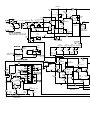
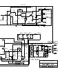
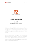
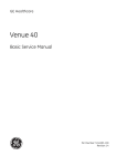
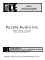
Purple Audio Inc.
MC76 Peak Limiter
Effective with serial number 001
The MC76 is a Monaural FET Peak Limiting Amplifier
Units of this type have been in wide use for many years to provide precise and automatic
control of peak signal levels in recording studios, disc mastering facilities, broadcast
stations and sound reinforcement applications. Operation of the MC76 Limiting Amplifier
should be very familiar to those who have used similar devices in the past.
UNITS FEATURE:
*Discrete Transistor Electronics
*Transformer Balanced XLR Inputs and Outputs
*Zener Shunt Regulated Power Supply
*Single Element Class A Output Amplifier
*Compression Ratios 4:1, 8:1, 12:1 and 20:1
*Fast Attack Time 20 microseconds to 800 microseconds
*Release Time 50 milliseconds to 1.1 second
*Gain 45dB (full gain with no limiting)
*VU Meter for output level and gain reduction indication
*Built In Stereo Interconnect with offset adjustment
*Heavy Gauge Stainless Steel Enclosure
*Purple Anodized Aluminium Front Panel
*120/240 volt operation
*3 Year Warranty
UNPACKING AND INSTALLATION
Your MC76 was packed with care at the factory. The packaging was designed to protect the
unit from rough handling. However, once the unit leaves us, it may pass through the hands
of those who have no idea what is in the box, may not be happy with work, may like to
throw things, don't care.... etc. Despite the heavy duty carton and foam blocks the unit was
packed with, we recommend you inspect the box and its contents immediately for any sign
of damage that may have occurred in transit. If there is damage, you should save all the
packing materials and contact your vendor and shipper immediately.
We recommend you keep the packing materials. Murphy’s law states that once you throw
away the box the likelihood you will need it back will increase in proportion to the square
of the distance from your service center multiplied by the cost
of replacement packing
materials.
The carton we ship out contains:
*One MC76 Limiting Amplifier
*This Manual
*One six foot (two meters) IEC Cable
*Warranty Card
The unit can operate safely and within specification over a range of ambient temperatures
from 0°C (+32°F) to +50°C (+122°F). Humidity is generally not a factor unless there is
condensation. One way to avoid condensation is to keep the ambient temperature reasonably
constant.
The unit can be powered from either 100-125 volt or 200-250 volt AC Mains at a line
frequency of 50 or 60 Hz. The operating voltage should be set BEFORE you plug the unit in.
The power inlet module integrates the voltage selector into the fuse holder. The selected
voltage (115V or 230V) will show through a smallwindow in the flip down “door” that
covers the fuse holder.
The unit should be supplied with an IEC cable applicable to your locality.
The fuses and voltage selection should be set up for you,
BUT NEVER ASSUME!!
Fuses:
At 115 Volts the unit should be fused for 1/8 Amps
At 230 Volts the unit should be fused for 1/16 Amps
Signal Connections are made via standard XLR connectors.
XLR Pin Assignments:
PIN 1 = Chassis, Earth, Ground
PIN 2 = Signal "Hot", Positive, ø+
PIN 3 = Signal "Cold", Negative, ø-
Wiring systems vary from facility to facility. PIN 1 may or may not be used to terminate a
shield or drain wire. In general this pin and the shield or drain wires connected to it are
not to be used to “Ground” or “Earth” the unit. Shields and Drain Wires should
NOT carry
current and are generally connected at only one end of any given wire. For your
convenience and to assure that the chassis can beeasily grounded (earthed) there is a
Chassis Ground Lug on the back of the unit and the center pin of the IEC power inlet is
connected to the chassis as well.
UNPACKING AND INSTALLATION - continued
PINS 2&3 of the input and output XLR connectors must be connected to get signal in and out
of the unit. Since the inputs and outputs are transformer balanced there
is no problem
unbalancing either the input or output or both. Because the input attenuator is ahead of
the input transformer taking PIN 3 of the input XLR to signal common is the preferred way
to unbalance the input. To maintain consistent phase from input to output connection of
PIN 3 to audio common is the preferred way to unbalance the output unless you
WANT to
flip the phase.
BRIEF OPERATING INSTRUCTIONS
Once the unit is set to the correct line voltage, plugged in and audio connected...
1) Set Input and Output Gain controls straight up to 12 O’clock. Do the same for Attack and
Release controls.
2) Pick a Ratio - a good place to start is 12:1 but any of the four available will do - higher
ratios will give a harder limiting effect while lower ratios will provide a softer compression
effect.
3) Set the meter select to GR or Gain Reduction.
4) Run the program material of your choice through the MC76.
5) Observe the amount of Gain Reduction on the meter. Adjust Input Gain and observe how
GR indication changes and listen to how the program material sounds.
6) Select Meter to +4 (or +8 if 0VU in your facility is referenced to +8dBu) and look at the
level coming out of the MC76. Set the Output Gain to a level that makes sense for you and
then return the Meter Select to GR after you set the output level.
7) Experiment
Note 1: Attack and Release times are quicker with clockwise rotation of controls. If you set
the release too quick the bass frequencies can modulate gain limiting at an audio rate. This
may not sound good on intruments like a bass guitar. Fast release does sound good in many
applications such as where bass frequencies are not a major component.
Note 2: If you turn the Attack control counter-clockwise until it clicks, this will disable
the limiter leaving only the gain which can be substantial. (Be mindful of your
speakers!)
Note 3:
Note 4:
You CAN push more than one Ratio button at a time.
The XLR connectors are wired Pin 2 hot.
Note 5: The VU meter should be left in GR mode during normal operation as it is
unbuffered and will add distortion to the signal if left hanging across the output.
OPERATING INSTRUCTIONS
The Attack Time of the MC76 is the time it takes for the detector circuitry and FET to respond
to a signal as it exceeds the threshold. This parameter is variable by the user since the
adjustment may have a significant effect on the sound of the program material.
The Release Time may be defined as the time it takes the limiter to return to its normal gain,
after the signal which has caused the gain reduction has dropped below the threshold. The
release time is variable for the same reason that Attack time is and can substantially alter
the sound of the program material passing through the MC76.
Together, Attack and Release times will define much of the sound or coloration in any given
application.
METER ZERO ADJUST
(Allow 15 minutes warm-up)
Push the "GR" meter function switch. The VU meter should read "0" on the VU scale since
the limiting function is disabled (the attack control knob is turned to OFF). If the "0"
indication has drifted beyond + or - 1 dB, it should be adjusted. This may be done through the
hole in the front panel located between the Input and Output level controls using a small
screwdriver. The trim pot is straight back through this access hole and requires a small
slotted screwdriver - service techs in the USuse a popular Xcelite screwdriver called a
"greenie".
STEREO INTERCONNECTION OF TWO MC76 UNITS
Two or more MC76 limiters my be connected for stereo or multi-channel operation as
follows. First remove signals from both limiters and disable gain reduction by rotating the
Attack controls fully CCW. Set the meter function switches for "GR" mode. Connect one
MC76 to the other by plugging a 1/4” “mono” patch cable (like a short guitar cable) from
the offset jack on one unit to the direct jack on another unit. Adjust the stereo offset on the
MC76 whose offset jack is used until both meters read zero. If the meters cannot be zeroed,
reverse the polarity (or “phase” on early units) and the meters can then be zeroed.
The same compression ratio should be selected in both units. Each limiter should be set-up
separately for threshold and output level before being linked together for stereo operation.
When the two MC76 limiters are interconnected, the Attack controls on both units will
interact, as will the Release controls. Since the timing capacitors are in parallel, the fastest
attack time will be double that of a single unit. Attack time on either limiter can be adjusted
separately to control both units. Maximum release time is the same as on an individual unit.
A good procedure is to set the release control on one MC76 limiter to maximum and to use the
release control on the other unit to control release time.
A given pair of MC76's will normally track properly through at least 10 dB of gain
reduction. In some instances, transconductance of the two FET's (Q1) will differ to the extent
that equal gain reduction will not be obtained as limiting is increased. This condition
is
more apt to be present in MC76's with widely different serial numbers, as the FET's within
the same factory production run are usually well matched. Should this anomaly be
observed, it will be necessary to select FET's for Q1 which match more closely in
transconductance. This should be handled at the factory.
DESCRIPTION
The MC76 is a gain limiting amplifier. Units of this type have been used for many years to
provide precise and automatic control of peak signal levels in recording studios, disc
mastering facilities, broadcast stations and sound reinforcement applications.
Gain reduction in the MC76 is accomplished using a Field Effect Transistor (FET) as a voltage
controlled variable resistor shunt. The FET is the first active component in the signal chain.
Large amounts of limiting can occur without large increases in distortion. There are four
compression ratios that can be used to best complement the program material and the
specific application.
Attack Time is continuously adjustable from less than 20µsec to 800µsec. The fast attack time
response is independent of peak frequency content or duration. Over the audio band the
full limiting action will stabilize in under a half cycle. Release time is continuously
variable from 50msec to 1.1sec. Release time is defined as the time it takes for the gain to
recover to within 63% of the normal non-limiting gain.
Provisions have been made for the interconnection of multiple MC76 Limiters. When
connecting multiple limiters (usually two for stereo) it is necessary to set the balance
between the two connected units. This linking circuit is built in to every MC76 and there is
a balance or offset control on the back panel next to the interconnection jacks.
GENERAL DEFINITIONS
Compressors and Limiters are used in many applications. A technical application for these
devices occurs when the dynamic range of program material is too large to be processed by
succeeding equipment, or when the peak-to-peak amplitude is too large for the headroom of
the following equipment. Compressors and Limiters are used to reduce the dynamic range of
the program material so it "fits" through the equipment and systems that follow. Good
examples are broadcast transmitters and public address systems. A non-technical
application occurs as a production or creative tool. Any device that changes dynamic range
will cause some subjective change in the sound of the program material. Reducing dynamic
range of an individual track in a multi-track recording and making it more consistent
makes it easier to control in the mixdown process. The applications as a production tool are
limitless.
The two different names (Compressors and Limiters) generally refer to the degree to which
the dynamic range is reduced. The relationship of input level change to output level
change is called the Compression Ratio. If, for example, an increase of 8 dB input signal
level should cause the output to increase by 2 dB, this would represent a 4:1 compression
ratio.
Amplifiers with compression ratios of up to 8:1are often considered to be Compressors,
while those with ratios higher than 8:1 are called Limiters. The MC76 can function
as a
compressor or a limiter since it has compression rations from 4:1 to 20:1.
Signals at levels below the threshold will not be affected by the compression/limiting
action. Any change in input level below threshold will result in a corresponding and equal
change in output level while increases in input levels that above the threshold will cause a
controlled decrease in amplifier gain resulting in a reduced increase in the output level in
proportion to the compression ratio. The MC76 Input Level control adjusts the amount of
signal to be processed above the threshold, and hence the degree of compression, or
limiting.
SPECIFICATIONS - ELECTRICAL
Note: the dB voltage level measurements listed here are referenced to
0.775 Volts RMS. We have seen dB measurements referenced to 0.775 Volts RMS labeled
interchangeably as dBu or dBv (note the little "v") while dBV (a big "V") uses 1 volt as a zero
reference... and to make things worse people still use the dBm scale to discuss voltage levels
across what they are measuring.... A dBm level is a measurement of power that references to
1mW dissipated into a given load and is almost always measured indirectly as a voltage
developed across a known load of 600 ohms. If someone tells us they are measuring +4dBm at
the input terminals of a device with a 10K ohm input impedance what are we to think? We
prefer the dBu scale because we are measuring voltages. Oftentimes, we are not measuring
across a 600 ohm "line" AND later when we read these specifications over the phone we
don't have to keep saying "dB little v"
Input: Constant Impedance Input Attenuator
Transformer Balanced and Floating
Input Impedance:
600 ohms at all input gain settings
Maximum Input Level:
+30dBu with limiting active and input cranked up full
(Prolonged exposure to signal levels in excess of +30dBu may burn up the input attenuator)
Maximum Gain:
45dB ±1dB
Frequency Response:
Output:
15Hz to 80KHz ±1dB typical
Floating Transformer Balanced
Output Load:
150 ohms or higher
Load Dependence:
The Output Level as measured while driving into a bridging load will
drop by no more than 1/2 dB when a load of 600 ohms is added - all other things being equal
- there will be a loss in headroom
Maximum Output Level:
+24 dBm into 600 ohm load (12-1/4volts)
+30 dBu into bridging load (24-1/2 volts)
SPECIFICATIONS - ELECTRICAL - continued
Distortion:
Less than 0.5% THD+noise 22Hz-22KHz with limiting activeRelease time set to
1.1sec (fast release times will increase distortion at low frequencies)NOTE:
The VU meter
should be switched to GR mode in normal operation as it is unbuffered and will add
distortion to the signal if left hanging across the output in the +4 or +8 settings
S/N Ratio:
>81dB at threshold of limiting 22Hz - 22KHz unweighted
Attack Time:
Less than 20µsec for full limiting action
adjustable to 800µsec with front panel control
Release Time:
Minimum 50msec adjustable to 1.1sec maximum (for 63% recovery) with
front panel control
Threshold and Ratio:
With the input control clockwise and the output gain control set
10dB below maximum (at about 6 on the dial)
The overall gain (before limiting) should be 35dB (±1dB)
The threshold of limiting is defined here as 1dB of limiting
at 20:1 the threshold of limiting will occur with an input of -24dBu (±2dB) and yield an
output level of +10dBu
at 12:1 the threshold of limiting will occur with an input of -25dBu (±2dB) and yield an
output level of +9dBu
at 8:1 the threshold of limiting will occur with an input of -26dBu (±2dB) and yield an
output level of +8dBu
at 4:1 the threshold of limiting will occur with an input of -30dBu (±2dB) and yield an
output level of +7dBu
Note: lower ratios make the limiting action kick in sooner
SPECIFICATIONS - ELECTRICAL - continued
Power Requirements:
100-125 Volts AC or 200-250 Volts AC selectable
At 115 Volts the current draw is 1/2 mA (typical)
and the unit should be fused for 1/8 Amps
At 230 Volts the current draw is 1/4 mA (typical)
and the unit should be fused for 1/16 Amps
Line Frequency can be 50-60Hz
Temperature:
0°C to +50°C
The MC76 can operate safely over a temperature range of
The MC76 can be stored over a temperature range of
-20°C to +60°C
SPECIFICATIONS - GENERAL
Dimensions:
2U 19" rack mounting enclosure (19" wide 3-1/2" high)
Depth behind front panel is 8" (not including connectors)
Finish: Front Panel is 1/8" thick aluminium purple anodized
with some variation in color - this can be viewed as a feature and lends a certain
individuality to each unit - Legends are silk screened in white
Weight: Unit - 12 pounds Boxed - 15 pounds
Accessories Included:
Optional Accessories:
IEC Power Cord and Manual
None
DESCRIPTION OF FRONT PANEL CONTROLS
Input Level Control:
Output Level Control:
Continuously adjustable rotary attenuator
Continuously adjustable rotary potentiometer
Attack Time:
Continuously adjustable rotary potentiometer
Ranges from the slowest attack time of 800µsec to the
fastest attack time of 20µsec at the full clockwise rotation
Limiting In/Out:
The Attack Time control has a switch position at its full
counter-clockwise rotation. This turns limiting action off
Release Time:
Continuously adjustable rotary potentiometer
Ranges from the slowest release time of 1.1sec to the
fastest release time of 50msec at the full clockwise rotation
Compression Ratio:
Four Position Interlocked Push-button Switch allows selection of 4:1,
8:1, 12:1 and 20:1 compression ratios. Some users enjoy pushing more than one of these
buttons at once.
Meter Function:
Three position switches selects VU Meter to read Gain Reduction or
Output Level referenced to +4dBu or +8dBu.
Power Switch:
The bottom switch bank with Meter Select is a button marked OFF. This
will turn the power to the unit off. Selecting any meter function (+8, +4 or GR) will turn the
unit on.
Gain Reduction "0" Adjust:
Screwdriver accessible adjustment via small hole in front
panel between input and output level controls
BACK PANEL CONNECTIONS AND CONTROLS
Audio Connections:
XLR type Input and Output
Pin 2 "Hot", Positive, ø+
Pin 3 "Cold", Negative, øPin 1 "Shield", Chassis, Ground
Stereo Interconnection:
Two 1/4" Jacks marked Direct to FET Buss and Offset of FET Buss.
Offset Control Pot and Battery Polarity Switch (Marked "Phase" on some units) allows for
compensation for variations in dc FET bias voltages between two or more units connected
for stereo or multi-channel operation (see instructions for this alignment)
IEC Power Inlet:
Accepts standard IEC type power cable and includes:
Fuse Holder - see back panel markings for fuse rating
Voltage Selection - integrated with fuse holder
Line Filter - this is NOT a spike suppresser
THINGS THAT BREAK OR WEAR OUT
Meter Lamps:
Two # 1819 Lamps 28 V 40 mA
Offset Battery:
AA type 1.5 Volt Lithium Cell (used for the stereo offset)
This is not rechargeable and you can use ANY 1.5 volt AA type battery. The Lithium
batteries have a better discharge curve making theoffset not drift as much over time.
Lithium Cells are harder to find but many camera/photo stores carry them.
VU Meter:
damage.
If you drop your MC76 the VU meter may fail even if there is no other obvious
REPAIRS AND WARRANTY
*We will service and repair the unit free of charge for threeyears from the date it is
shipped. We track warranty by serial number therefore make sure to leave the serial
number tag on the unit. This is a transferable warranty and covers the whole unit except
the battery (used for stereo offset) and meter lamps. We will not repair damage that results
from misuse, abuse or neglect. We do not guarantee that the purple color of every unit will
match the purple of every other unit.
Should a malfunction occur, the dealer whom you purchased this unit from will be able to
handle return for factory repair. Please call or write to the factory for a RETURN
AUTHORIZATION NUMBER
which must accompany all repairs. For prompt service, ship
the unit prepaid directly to the factory with the
RA NUMBER VISIBLE
on the shipping
label. Be sure it is well packed in a sturdy carton with shock absorbing material. Tape a
note to the top of the unit describing the malfunction and instructions for return. We will
pay one-way return shipping cost on any in-warranty repair.
Because of specially selected components in this product, field repairs are not authorized
during the warranty period. Attempts to perform repairs may invalidate the warranty.
Even if your unit is out of warranty, we recommend that you return it to the factory for
repairs. Our experienced personnel, supported by special test equipment, will be able to find
and eliminate any problem in the most efficient way.
MAINTENANCE - continued
INTERNAL SERVICE ADJUSTMENTS
These controls have been set at the factory and should not require adjustments except after
service work. If re-calibration is necessary, the test procedure that follows should be
performed very carefully, and adjustments performed in the exact manner and order
specified.
Before attempting any calibrations, the limiter should be on for at least 15 minutes. This
avoids subsequent drift.
WARNING: The full AC line voltage is present at several points inside
chassis. Be careful to avoid personal shock when you work with the limiters
with the covers removed
.
the
POWER SUPPLY
The positive DC voltage should be at +30 volts (+or- .5) the test point to measure the level is
top trace end of R51.
The level of the negative voltage supply is a fixed -10 volt (+- .5), The test point is the anode
of CR9.
"Q" BIAS ADJUSTMENT - (R59, internal trimpot)
This is a very important parameter to assure the linear operation of the limiter. Therefore
the adjustment should be performed very carefully. Set the controls as follows:
Input = "24" mid rotation
Output = "24" mid rotation
Attack = full CCW (switched to off position)
Release = full CW
Compression ratio = 20:1
Meter mode = "GR"
Q-bias adjustment = full CCW
MAINTENANCE - continued
Apply a signal (1 KHz, O dB) to the input, and adjust the output to read +11db as read on an
external meter. Slowly turn the Q-bias adjust (R59) CW until a drop of 1 dB occurs, and the
external meter reads +10db. This places the gain reduction FET Q1 slightly into conduction.
GAIN REDUCTION METER TRACKING - (R75, internal trimpot)
Due to interaction of the adjustments, this procedure may have to be repeated to achieve
satisfactory tracking.
Setup:
No signal
Disconnect R44
Voltmeter across R74
Calibration
1.
2.
3.
4.
Zero MC76 "GR" meter with R71 (Thru front Panel Zero Adjust)
Adjust pot R75 for 0.0 Volts across R74.
Repeat 1 & 2 until both conditions are met.
Set controls as follows:
Input = "24" mid rotation
Output = "24" mid rotation
Attack = full CW
Release = full CW
Compression ratio = 20:1
Meter mode = "GR"
5. Apply a signal (1 KHz, 0db).
6 Set output control for 0db as read on an external meter.
7. Set attack full CCW (off position). Set input control for +10db as read on an external
meter.
8. Turn the attack control OFF (CCW) and readjust the output level control for "0" if
necessary.
9. Repeat 7 & 8 until the output drops 10dB whenever the attack control is turned ON.
10. Reconnect R44.
MAINTENANCE - continued
SIGNAL PREAMP LINEARITY
This control (R86) is in the feedback loop of the amplifier and affects the operation of Q1. It
will never be necessary to perform any adjustment of R86 unless resistors in this section of
the circuit have been replaced. If adjustment is required, set the controls as follows:
Input = Full CW
Output = to number "18" on the front panel
Attack = full CCW (switched to off position
Release = Full CW
Compression Ratio = 20:1
Meter mode = "GR"
Apply an input signal (500 Hz, -30 dB) and measureTHD of the resulting output signal.
Adjust R86 until the minimum amount of distortion is achieved.
CLEANING THE LIMITER
The front panel of the MC76 may be cleaned with a non abrasive cleanser such as Formula
409, or "Fantastic" applied with a softclean cloth. Additional protection of the anodized
panel can be afforded through a light application of a spray wax preparation such as
Pledge. NOTE: NEVER SPRAY THE PANEL DIRECTLY AS THE CLEANSER OR WAX MAY
ADVERSELY
AFFECT CONTROLS OR METER, AND CAN CONTAMINATE
CIRCUIT
BOARDS IF IT PENETRATES THE CHASSIS.
NEWS and...
If you lose this book but have a computer connected to the internet you will be able to find
it on the Web at “http://www.purpleaudio.com”.
PRE-AMP
R13
1M
C4
100uf/25v
+
C815
.1uf
R9
C1
1uf
R8 560K
1K
C817 .1uf
Q2
2N3391A
R10
10K
R85
150
R84
180
R6
2.2M
C6
200pf
R1000
2K
C3
200pf
C5
100uf/25v
R86
100
P.C.B.
R21
56K 1/4W
4:1
R22
47K 1/4W
AA Battery
R23
250K 2W
Output F.P.
R15
6.8K
S1000
2PDT
R1001
100K
+
C9
.22
C22
.22
R7
2.2M
C7
1uf/50v
R12
910
C816
.1uf
100uf/25v
R11
82
R18
180
C28
100uf /25V
C600
Q3
2N3391A
C2
27pf
+
T1 UTC 0-12 or Equivalent R5
27K
R3
R2
1
2
6
620 1/4W 620 1/4w
R4
3
7 270
Q1
4
2N5457
5
8
R1B
Q14
2N3391A
+
R1A
6.8K
R17
R14
22K
R19
R78
R20
56K 1/4W 68K 1/4W 56K 1/4W
8:1
12:1
20:1
(T&C)
C1000
100uf/25v
R79
15K
R38
47K
C814
.1uf
Bypass on R55 Attack
R77
8.2K
R65
R67
3.9K
Q12
2N5088
R37
470K
R69
1.5K
R75
2K Null Adj P.C.B.
R71
2K
"0" Set F.P.
METER DRIVER
Q7
2N5088
R73
680
R76
8.2K
Q8
2N5088
Q9
2N5088
R42
180K 1%
R40
2.4K
R39
4.7K R41
270
Q13
2N5088
R44
(T&C) ~1K
R70
4.7K
R72
1.5K
1uf/50v
R74
2.7M
R68
1.5K
10K
R66
+
R16 3.6K
R47
44.2K 1%
R36
1M
C17
Q11
2N5457
R51
4.7K
C18
100uf/50v
+
R48
7.68k 1%
R43
38.3K 1%
R50
180
R46
47K
SIDECHAIN
R49
2.4K
OUTPUT AMP
R26
68K
R29
1.2M
BROWN
BLUE
+
C10
1uf/50v
C15
.0047
R35
560
R34
8.2K
C11
10pf
R24
2.7M
Q6
2N3053
Q4
2N3391A
C8 .15
R25
2.7M
Q5
2N5088
C12
R30
200K 100uf/25v
R27
1.5K
utput F.P.
YELLOW
BLACK
CR1
IN4148
ORANGE
C819
.1uf
C601
100uf/25v
+
C818
.1uf
C14
.033
C13
270pf
R31
10K
RED
WHITEBLACK
GREY
WHITERED
VIOLET
R32
39
R28
27K
R61
470 1/4W
4:1
8:1
R62
R63
560 1/4W 1.5K 1/4W
R45
12:1
R64
1.5K 1/4W
20:1
10M 1/4W
R58
150
30v/10w SK170
1N2989A & B ECG5202A C810
.1uf
Shunt Zener
C27 .022
CR28
R54
Q10
2N5088
+
C19
10uf/35v
R52
47K
+
R53 C813
C20 47K .1uf
10uf/35v
C809
C24 .1uf
3300uf/35v
+
470
CR2
R55
25K 1/2W
FDH333
Release Control F.P.
C21
100uf/25v
R56
5M 1/2W
+
R49
2.4K
FDH333
CR3
R59
2K
C812
.1uf
CR9
10v 1N4740
R57
270K
R35
10K
R60
3.9K
T3
DS1
C26
+
3300uf/35v
C811
.1uf
R82
1K
C808
1819
DS2
+
C23
3300uf/63v
1819
+
R81
1K
BLACK
CR4 1N4936 RED1
C805 .1uf
REDYELLOW
CR5 1N4936
C807
C25
3300uf/35v
.1uf
.1uf
CR6 1N4936
C806 .1uf
BLACKWHITE
GREY
RED2
GREYWHITE
CR7 1N4936
Copyright © 1997 permission given
to copy with proper acknowledgement.