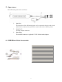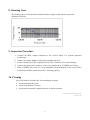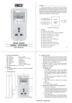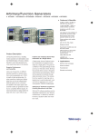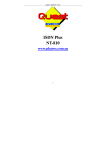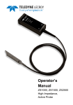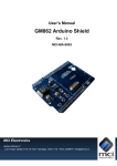
1
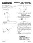
800MHz DIFFERENTIAL PROBE
USER’S MANUAL [LDP-800]
This probe is in compliance with IEC-61010-031 CAT I, Pollution Degree 2.
1. Safety Terms and Symbols
Terms appear in this manual:
________________________________________________
WARNING. Warning statements identify conditions or practice that
could result in injury or loss life.
________________________________________________
CAUTION. Caution statements identify conditions or practice that
could result in damage to this product or other property.
Symbols appear on the product:
Danger
High Voltage
Protective
(Earth) Terminal
Attention
Refer to Manual
2.General Safety Summary
Review the following safety precautions to avoid injury and prevent damage to this probe
or any products that connected to it.
Observe Maximum Working Voltage
To avoid any injury, do not use the probe under the condition that the voltage between
either input lead or earth is above 40Vrms CAT I. This voltage rating applies to 1/10
setting.
1
Must be Grounded
This probe is grounded with the shell of BNC connector and an auxiliary grounding terminal,
through the grounding conductor of the power cord of the measurement instrument.
Before making connections to the input leads of this probe, ensure that the output BNC connector
is attached to the BNC connector of the measurement instrument and the auxiliary grounding
terminal is connected to a proper ground, while the measurement instrument is properly
grounded.
Do Not Operate Without Covers
To avoid electric shock or fire hazard, do not operate this probe with covers removed.
Do Not Operate in Wet/Damp Conditions
To avoid electric shock, do not operate this probe in wet of damp conditions.
Do Not Operate in Explosive Atmosphere
To avoid injury or fire hazard, do not operate this probe in an explosive atmosphere.
Avoid Exposed Circuit
To avoid injury, remove jewelry such as rings, watches, and other metallic objects. Do not touch
exposed connections and components when power is present.
Use Proper Power Source
To ensure this probe function well, use a 9V cells or regulated 15VDC/100mA mains adaptor or
power lead. Do not operate this probe from a power source that applies more than the voltage
specified.
Do Not Operated With Suspected Failures
If you suspect there is damage to this probe, have it inspected by qualified service personnel.
2
3. Description
By enabling conventional oscilloscopes to display and measure in-circuit waveforms that are
inherently differential signals, the differential probe extends the measurement capability of
oscilloscopes in digital communication and high speed digital circuits.
4. Installation
a. Simply plug-in the BNC output connector to the vertical input of a general purposed
oscilloscope or other measurement instrument, and connects the auxiliary grounding
terminal to a proper ground. The measurement instrument must have a ground referenced.
b. Connect an appropriate power source to this probe and then turn it on.
WARNING. To protect against electric shock, use only the
accessories supplied with this probe.
c. Using the appropriate probe accessories, connect the inputs to the circuits under
measurement.
CAUTION. This probe is to carry out differential measurement
between two points on the circuit under measurement.
This probe is not for electrically insulating the circuit
under measurement and the measuring instrument.
3
5. Appearance
The differential probe looks as follows.
1.
2.
3.
Input Pins:
The input pins of the differential probe can be connected directly to the circuit
under tests or connected to optional accessories that come with the probes.
Output Lead:
The BNC output connector.
Power Plug:
The terminal connects to regulated 15VDC/100mA mains adaptor.
6. SMD Micro Tests Accessories
Descriptions
4
Quantity
MicroFlex Pincer, Black
1
MicroFlex Pincer, Red
1
Micro Test Clip, Black
1
Micro Test Clip, Red
1
MicroLead, 0.8mm J-P, 5cm, Black
1
MicroLead, 0.8mm J-P, 5cm, Red
1
MicroLead, 0.8mm J-P, 10cm Black
1
MicroLead, 0.8mm J-P, 10cm Red 1
1
Twin Pin, 16.8mm
2
Twin Pin, 12.8mm
2
Test Tip, 0.8mm
6
7. Specifications
Bandwidth
Attenuation Ratio
Accuracy
Rise Time
Input Impedance
Input Voltage*
DC to 800MHz (-3dB)
1/10
±2%
0.4375ns
100kΩ//2pF each side to ground
- Differential Range
- Common Mode Range
- Absolute Max. Voltage
(either input to ground)
Output Voltage
- Swing
- Offset (typical)
- Noise (typical)
- Source Impedance (typical)
CMRR (typical)
Power Requirements
±15V (DC+peakAC)
±30V (DC+peakAC)
±40V (DC+peakAC)
Ambient Operating Temperature
Ambient Storage Temperature
Ambient Operating Humidity
Ambient Storage Humidity
Length of BNC Cable
Length of Input Leads
Weight
Dimensions (LxWxH)
*
±1.5V (into 50Ω load)
<±5mV
0.3mVrms
50Ω (for using 50Ω input system oscilloscope)
60dB @60Hz, 15dB @500MHZ
Regulated 15VDC/100mA mains adaptor
-10 to 40℃
-30 to 70℃
25 to 85% RH
25 to 85% RH
120cm
50cm
130gms
111mm x 22mm x 14mm
Voltage limit is the lesser of the DC+Peak AC and RMS values..
**
a. The supplied voltage must be less than 16V and greater than 3.3V, otherwise the probe could
be damaged or can’t be operated properly.
b. For wrong polarity of power sources, a built-in circuit will protect the probe and no danger or
damage will occur.
c. When the voltage of the cells become too low, the power indicator on the panel will change
its color and then distinguish.
5
8. Derating Cure
The derating curves of the absolute maximum input voltages (either input to ground) is
illustrate as follows;
9. Inspection Procedure
a. Connect the BNC output connector to the vertical input of a general purposed
oscilloscope.
b. Connect AC mains adaptor to this probe and then turn it on.
c. Set the oscilloscope to DC coupling and 0.5V/div. Center the trace on the display.
d. Connect the inputs of the probe to a sine-wave signal source of 100KHz and 10Vp-p.
e. Then, a 100KHz sine-wave of 1 Vp-p amplitude will be displayed on the screen of the
oscilloscope and this means the probe is working properly.
10. Cleaning
Use a soft cloth to clean the dirt. Prevent damage to probe.
a. Avoid immersing the probe.
b. Avoid using abrasive cleaners.
c. Avoid using chemicals contains benzene or similar solvents.
Lemo® and Probus® are the registered trademarks
Date: May 1,2009
6