1
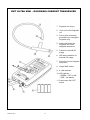
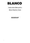
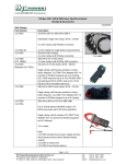
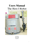
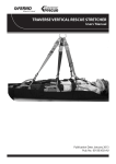
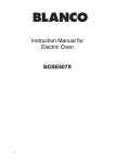
INTRODUCTION
PEM’s Rogowski Current Waveform Transducers combine high bandwidth, safety, and the minimum
disruption to the circuit under test. These instructions should be followed whenever the unit is used.
They are intended to help you obtain the best and safest performance from the transducer.
SPECIFICATION
ACCURACY (5 to 100% full scale)
Within the limits of bandwidth, Peak di/dt and low frequency noise that are specified on the relevant
CWT specification sheet.
Calibration:
Normally ±0.2% (traceable to UKAS) with the
conductor central in the Rogowski loop. See the
calibration certificate for more details.
±2% typ. variation of accuracy with conductor position
in the loop (see ‘Obtaining The Best Measurement’)
±0.05% typ.
Positional accuracy:
Linearity:
POWER SUPPLY
The CWT can be powered by both battery and an external DC voltage. With the external DC supply
present the batteries are inoperative.
Battery type:
Battery life:
DC socket type:
DC voltage:
DC quiescent supply current:
4 (four) 1.5V AA alkali
30 hrs typ.
2.1 or 2.5mm jack socket – polarity indicated on front of
CWT
12V DC (±10%)
70mA @ 12V DC
OUTPUT
Maximum output voltage:
Output cable:
Minimum output loading:
±6V (corresponding to ±Peak Current Rating of CWT)
0.5m BNC to BNC 50Ω cable
≥ 100kΩ (for rated accuracy – recommend DC1MΩ on scope)
= 50Ω (for driving long cables > 10m)
NB. A load of 50Ω will reduce the CWT sensitivity by half it’s
normal value. It will also reduce the peak output to ±2V)
OPERATING TEMPERATURE RANGES
Rogowski coil and cable
Integrator electronics
February 2011
-10oC to 70oC
0 to 40oC
2
CWT ULTRA MINI – ROGOWSKI CURRENT TRANSDUCER
1. Rogowski coil (loop)
2. ‘Free end’ of the Rogowski
coil
3. Ferrule (the connecting
mechanism for closing the
Rogowski coil).
4. Cable connecting the
Rogowski coil to the
integrator electronics
5. Socket for external DC
supply
6. LED status indicator for
external DC supply
7. Enclosure for the integrator
electronics
7
10
11
8. Output BNC socket
9. 4 x AA batteries
10. LED indicator
- GREEN - CWT is ON
- RED – low battery
11. Push button ON / OFF
switch
8
February 2011
9
3
SAFETY AND PRE-USE CHECKS
Throughout this instruction sheet there are a number of warnings which must be observed to ensure
safe operation of this unit. These warnings are identified by the following symbol:
PEM accepts no responsibility for any accidents or damage resulting from careless use, or nonobservance of these instructions.
THE ULTRA MINI ROGOWSKI COIL
The integrity of the insulation around the Rogowski coil itself should be VISUALLY
INSPECTED before use, and the unit should NOT BE USED if there are signs of
damage.
When bending the flexible coil around a conductor, avoid tight bends and sharp edges
that could damage the coil.
The voltage rating (safe PEAK working voltage) is clearly labelled on the cable
adjacent to the coil. For the CWT Ultra Mini this is 1.2kV peak. Never use at voltages
greater than this value.
Voltage ratings are only valid if the ‘free-end’ of the coil is fully inserted into the socket,
and remains fully inserted during use. The coil has a friction fit, the coil is fully inserted
when the user feels they can ease the coil free end into the ferrule no further.
The voltage ratings are appropriate for intermittent use of the CWT as a test
instrument and not for continuous use in a permanent installation.
The ratings are derived from the following standard test: Coils rated for 1.2kV peak
are flash tested for one minute at 3.0kVrms using a 50Hz sine-wave voltage.
For permanent installation the coil should be situated such that corona, which will
eventually damage the coil insulation, cannot occur. For information regarding
permanent installation of PEM’s Rogowski coils on high voltage equipment please
consult PEM.
THE INTEGRATOR
The CWT must only be used with oscilloscopes or monitoring equipment which have
their BNC INPUTS PROPERLY GROUNDED.
February 2011
4
HANDLING INSTRUCTIONS
To achieve such an extremely thin Rogowski coil the CWT Ultra Mini is necessarily delicate.
Every effort has been made to ensure that the CWT Ultra Mini is as robust as possible. To prolong
the life of the coil please observe the following handling instructions.
The free end of the coil is unclipped in the direction shown.
OPEN IN THIS
DIRECTION
When clipping or unclipping the coil, hold the ferrule as shown
Never force the free end of the coil into the ferrule. This may damage the coil
insulation.
Take care not to put any force onto the cable attached to the coil. This may damage
the coil.
When not in use return the CWT Ultra Mini coil to its protective cover.
February 2011
5
SWITCHING ON
Before installing the CWT and taking a measurement refer to SAFETY AND PRE-USE
CHECKS and HANDLING INSTRUCTIONS to ensure safe operation of your CWT
Ultra Mini.
Do not fit a Rogowski coil to a live circuit; always de-energise the circuit first.
1. Connect the BNC plug on the output cable of the transducer to your oscilloscope or current
monitoring equipment. The CWT must only be used with oscilloscopes or monitoring equipment
which have their BNC INPUTS PROPERLY GROUNDED.
2. Having carried out the VISUAL INSPECTION of the Rogowski coil, un-clip the coil and wrap it
around the de-energised conductor under test.
3. Insert the free-end of the coil fully inside the ferrule.
4. Re-energise the conductor.
5. The CWT is switched ON by pressing and releasing the ON push button, and is turned OFF by
depressing the button fully; the LED indicates that the CWT is ON when the LED is GREEN.
6. Four 1.5V AA alkali batteries provide about 30 hours operation. Battery voltage is continuously
monitored; healthy batteries are indicated by the GREEN LED. If the LED is RED the batteries are
delivering less than 2V and must be replaced by removing the sliding battery door in the back
cover of the integrator enclosure.
The units can also be powered by an external DC supply. The DC voltage is 12 V (±10%). When
the DC supply is present a RED indicating LED adjacent to the socket is illuminated. With the DC
supply present the batteries are inoperative.
7. After switch-on the CWT requires a settling down time to attain its quiescent state before
providing correct current measurement. The time, which depends on warm-up and low frequency
bandwidth, can be as long as 2 minutes.
February 2011
6
OBTAINING THE BEST MEASUREMENT
The Ultra Mini Rogowski coil should be positioned so that the conductor under test is encircled by the
coil but is not adjacent to the cable attachment (see picture below). The diagram shows the direction
a positive current should pass through the coil loop in order to obtain a positive output voltage. The
CWT has been calibrated with the conductor near the centre (position A), and this is the ideal position
for accuracy.
For the best high frequency performance the centre of the current should lie on the line shown A to B,
where B is half way around the circumference of the coil.
B
I current
into page
A
KEEP CONDUCTORS
AWAY FROM
SHADED AREA
The sensitivity of the CWT to currents that do not pass through the coil is very small, provided that
such currents are no greater than the CWT’s rating or such currents are relatively distant from the
coil. In the vicinity of a multi-turn inductor the ‘H’ field is far stronger than from a single conductor
carrying the same current, and such positions should be avoided.
Similarly if there is a surface with a high voltage very close to the coil, and the voltage is subject to
high rates of change (e.g. several 100 V/µs) or high frequency oscillations in the MHz range, then
measurement error can arise due to capacitive coupling to the coil.
As a check on any unwanted response to adjacent fields, it is wise to display the output of the CWT
when close to (but not encircling) the conductor whose current is to be measured. This will reveal the
magnitude of any unwanted response to currents close to but outside the coil.
EMC
EMISSIONS
PEM’s Rogowski current waveform transducers are certified to: BS EN 50081-2:1994
IMMUNITY
PEM’s Rogowski current waveform transducers are certified to: BS EN 50082-2:1995
February 2011
7