1
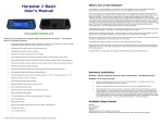
Herpstat 1 & Herpstat 2
User’s Manual
www.spyderrobotics.com
Thank you for choosing the Herpstat digital proportional thermostat. This product
offers the following features:
•
Proportional heating constantly monitors and adjusts amount of heat necessary to maintain a target
temperature (usable range from 40˚F to 150˚F or 4˚C to 65˚C).
•
Soft startup slowly applies power during initial warm-ups.
•
Configurable for Heating, Cooling, Lighting, and Humidity.
•
Lighting can simulate sunrise/sunset and moonlight.
•
User selectable temperature and light ramping allows day to night changes to occur slowly.
•
Sensor Matching allows the user to digitally calibrate the sensor output to match other equipment.
•
Auto Power Matching constantly adjusts the power output curve to match the enclosures efficiency.
•
Individually selectable day/night schedules with nighttime temperature settings for each output.
•
High/Low temperature tracking helps monitor heating system and enclosure efficiency.
•
Individually selectable High/Low temperature threshold alarms.
•
Precision temperature sensors with an internal resolution of .1125 ˚F and are accurate to ± .9 ˚F
•
Display and setting in tenths of a degree.
•
Security Passcode option deters vandals.
•
All settings are retained in memory even if power is lost.
•
Power Outage detection/tracking.
•
Temperature can be set/displayed in Fahrenheit or Celsius.
•
Easy to read backlit LCD display.
•
Removable sensors allow for easy replacement if necessary.
•
User replaceable fuse.
•
Audible alarm system
•
Internal error detection shuts off heat if sensor fails or is disconnected.
•
Internal safety relay cuts power to all outputs if user settable conditions are met.
•
700 total watt output for the Herpstat 1
•
900 total watt output for the Herpstat 2
•
1 year limited warranty
About this User's Manual
This manual covers both the Herpstat 1 and Herpstat 2 products. The Herpstat 2 essentially adds a second
output and probe with its own independent primary settings.
What's new in this Herpstat?
The Herpstat line of thermostats has a reputation as the most reliable and user customizable thermostats
geared directly towards the reptile industry. With our latest four output model (Herpstat 4) several new
advancements in technology were added. We took these new features and added an all new hardware design to
create the Herpstat 1 and Herpstat 2 models. Here are a few highlights of those features:
A new revolutionary way of controlling the temperature has been implemented. Most thermostats apply full
power when plugged up. However, this is not always ideal. For example, if your power goes out and you have
eggs in an incubator. When the power comes back on, the heat element (typically at the bottom of the
incubator) turns full on and the eggs on bottom can be subjected to the immediate heat. The Herpstat now has
a "soft power" state that will slowly advance the power a single percent around every second or so. If the temp
seems to be rising too quickly (a tenth of a degree per loop) it will stop or back off a percent. There is also a
completely new routine that will figure out the best power output curve in the last two degrees before the target
temp. This allows the Herpstat much better control for some of the weaker heating devices as well as
overpowering ones. This is all automatic and requires no settings to enable.
Temperature ramping has been added. The Herpstat can slowly ramp up and down between the day and night
time temperature settings. The amount of time is user selectable up to 10 hours.
Lighting control ramping was also added. Using this feature can more closely mimic natural lighting. We also
added a fully user adjustable nighttime power setting which can be used to mimic moonlight.
Safety has been enhanced by adding a mechanical relay to the power circuit. If enabled by the user, this relay
can remove power to all outputs during an error or High/Low condition. Adding this to the audible alarms and
built in error detection code makes this unit very safe.
Humidity control is now built in. This can be used to connect foggers, misting pumps, and other humidity
devices. The Herpstat can work with these in a time-based fashion right out of the box. Optional humidity
sensors can be purchased to allow full control with humidity sensing capabilities.
(Hardware Installation continued...)
Available Output Modes:
Disabled
Heat (Dimming)
Heat (Pulse)
Cooling
Lighting (ON/OFF style for fluorescents)
Lighting (Dimming style for incandescent and some transformerless LED lights)
RH Scheduled
RH Sensed (optional humidity sensor needed)
RH Hybrid (optional humidity sensor needed)
Installation Tips:
We do not recommend using aluminum tape to secure the probes. This can cause false readings and
poor regulation.
If possible, route the probe wires so that they are not in direct contact with the 120vac cables going to the
heating devices. Preferably leave at least a few inches between the probe wires and the AC lines to avoid cross
talk/electrical interference issues.
The vent holes on the bottom and rear of the device provide proper cooling. Mount the device in dry location
away from additional heat sources. During operation it is normal for the Herpstat's enclosure to warm to the
touch.
Electrical surges can often damage a thermostat. Use a good quality surge suppressor connected to the wall
outlet and plug the Herpstat into it when possible.
Setup Procedure
Note: The Enter button is used to select options while the Plus and Minus buttons are used to alter
the options or navigate the menu. If no selection is made after a period of time the unit will return
to operation automatically. While in the menu system all AC power to the outputs are turned off for
safety. Note: Adjust the Time and Date to insure proper operation.
The High/Low temperature tracking now keeps track of the time and date when it was recorded. This helps
identify when the peaks are happening and can help fine tune the environment.
An updated menu design and larger LCD makes it even easier to adjust the settings.
EEPROM memory error detection now double-checks to make sure all user settings written to the eeprom
memory were saved correctly.
Pulse Proportional mode was added. On some metal rack systems dimming style proportional can generate a
audible hum in the rack. Pulse style proportional can help eliminate the hum while still providing varied power
to the heating device.
Grounded outlets (3-prong plugs) were added to accommodate more types of heating devices.
Hardware Installation
WARNING – FIRE OR ELECTRICAL SHOCK MAY RESULT FROM MISUSE. FOR INDOOR USE ONLY!
Herpstat 1: Do not exceed 700 watts.
Herpstat 2: Do not exceed 500 watts on either output or 900 total watts.
1.
Each AC receptacle on the Herpstat has a corresponding probe jack next to it. For heating or cooling
use attach a temperature probe. For humidity control an optional humidity sensor can be
connected. For lighting control or for a disabled output the probe jack can be left empty.
2.
Attach the Herpstat electrical cable to the back of the unit and to a standard wall outlet.
3.
After setting the correct mode of operation in the menu attach the appropriate devices to the AC
outlet receptacles. These devices may include heat tape, heat coils, mats or other resistive load
heating devices. Not recommended for use with rock heating devices or other devices that come in
direct contact with the animal. In cooling mode the outlets can be used for 120V emergency fans.
For controlled lighting incandescent lamps and some transformerless LED lamps can be used.
Misting pumps and foggers can be used for humidity control. Do not connect oil-filled heaters or
other space heaters.
NOTE: On the Herpstat 2 the outlet #1 is on the left side and outlet #2 is on the right side if you
are looking at the back of the unit.
Press the Enter button to display the initial menu screen. This screen allows you to select which Output to
configure, the System Setup, Security Passcode, and the Safety Setup. Each output has its own individual
settings. All settings in the unit are stored in non-volatile eeprom memory which is retained during a power
outage.
Navigate to the System Setup option and press Enter.
System Setup
(System Setup continued...)
(Output Setup for Temperature Control continued...)
Display Type:
This setting adjusts whether to display temperature in Celsius or Fahrenheit.
Enable System Sounds:
Enables or disabled the system beep during menu selection. Does not affect audible alerts.
Master Reset:
Selecting this will reset all settings in the device to factory defaults.
SetTime:
This setting adjusts the system clock's time. While setting the time the Plus button increments the hour and the
Minus button increments the minute.
SetDate:
This setting adjusts the system clock's date. While setting the date use the Plus and Minus buttons to adjust the
setting and the Enter button to advanced to the next setting.
Output Setup for Temperature Control
From the initial menu screen select an output using the Plus and Minus button and press Enter. The number in
the upper right indicates which output you are adjusting. The arrows indicate if there are additional menu
choices to toggle through.
Enable Nite Cycle (OFF / ON)
To Enable/Disable the Nite Cycle press the Enter button while on this display.
Nighttime Temperature:
This setting is the temperature the device will maintain during the Nite Cycle.
NiteCycle Start Time:
This setting adjusts what time the Nite Cycle starts.
NiteCycle End Time:
This setting adjusts what time the Nite Cycle ends.
Ramping:
This setting adjusts how long it will take to switch between the DayTemp and NiteTemp settings allowing a
smooth transition up to 10 hours.
High / Low Alarms Menu:
Enter this menu to set the audible High / Low Alarm feature.
Enable H/L Alarm (OFF / ON)
To Enable/Disable the High/Low Alarms press the Enter button while on this display.
High Temp Alarm:
This setting is the highest temperature at which the audible alarm triggers if breached for the selected output.
Output Mode: (Heat (Dimming), Heat (Pulse), Cooling)
Note: When the Mode is changed all settings for the selected output will be set to the defaults.
Heat (Dimming) can adjust the voltage output to the heating device similar to a household dimmer. In most
cases this is the best performing mode of control.
Heat (Pulse) can provide varied lengths of pulsed power to the heating device. This method of control can help
avoid the audible hum on metal rack systems .
The Cooling mode is a non-proportional mode that applies power when the set temperature is breached. The
Cooling mode then powers off the output when the temp drops below the Swing setting.
Daytime Temperature:
The Daytime Temperature setting is the temperature the device will try to maintain during the Day Cycle. If the
Nite Cycle is disabled then the Daytime Temperature setting will be used for the full 24hrs.
NiteCycle Menu:
Enter this menu to adjust settings if a different temperature is required during the night.
Low Temp Alarm:
This setting is the lowest temperature at which the audible alarm triggers if breached for the selected output.
Low Alarm 30 min Mute (OFF / ON)
This setting by default is disabled and is only available in temperature related modes. This will mute the low
temperature alarm for 30 minutes anytime the low alarm is triggered. This is useful to allow time for the
temperature to reach the target setting or if a door is open while maintaining an incubator. If the Low Alarm is
triggered you can reactivate the mute by entering the menu or by pressing the PLUS button on the main display
that shows the probe temperatures. This will allow another 30 minutes before the Low Alarm becomes active
again.
Sensor Adjustment:
The Sensor Adjustment setting is used to alter the temperature read by the temperature probe to match other
equipment. Note: The sensor used in the Herpstat Probes are typically more accurate than most other
equipment. Adjustments to this setting are usually not necessary.
Temperature Swing:
This setting is available in the Cooling mode. This controls the range of temperature before the output is reenabled after it has made it to the Daytime Temperature or Nitetime Temperature setting.
Output Setup for Lighting Control
From the initial menu screen select an output using the Plus and Minus button and press Enter.
(Output Setup for Lighting Control continued...)
(Output Setup for Humidity Control continued...)
Output Mode: (Lights ON/OFF, Lights Dimming)
Note: When the Mode is changed all settings for selected output will be set to the defaults for that particular
mode.
Output Mode: ( RH Scheduled, RH Sensed, RH Hybrid )
Note: When the Mode is changed all settings for selected output will be set to the defaults for that particular
mode. RH Sensed and RH Hybrid mode require the optional Herpstat Humidity Sensor sold seperately.
Select the Output Mode option and set it to either Lighting (ON/OFF) or Lighting (Dimming). The ON/OFF mode
will switch the output fully on or off and is used for fluorescent lighting. Dimming mode can be use with
incandescent lights and many types of transformerless LED lighting and can adjust the power going to the lights
to provide simulated sunrise, sunsets, and moonlighting.
Select the Output Mode option and set it to either RH Scheduled, RH Sensed, or RH Hybrid. RH Scheduled can
be used to set up to nine separate scheduled times when a humidity device will power up and does not require a
sensor. RH Sensed has no scheduled times and uses sensor feedback to determine if a humidity device will
power up. RH Hybrid mode combines the two and you can select up to eight scheduled times when a humidity
device will power up. Then during that session it checks the sensor and if the humidity level is below the RH
setting it will activate the output. If the level is above the RH setting the power will not be applied.
Daylite Power:
This setting adjusts the amount of power applied during the Day Cycle.
Nite Cycle Options:
Enter this menu to adjust settings if a different light output is required during the night.
RH %
Note: Only available in Humidity Sensed or Humidity Hybrid modes.
This setting adjusts the highest level of relative humidity. Once this amount has been breached the power will
shut off to the output.
Schedule:
Enter this menu to set the scheduled times to activate a humidity session.
Note: Only available in Humidity Scheduled or Humidity Hybrid modes.
Enable Nite Cycle (OFF / ON)
To Enable/Disable the Nite Cycle press the Enter button while on this display.
Nitelite Power:
This setting adjusts the amount of power applied during the Nite Cycle.
In this menu use the Plus and Minus buttons to navigate through the available slots. Advancing through all of
the slots will bring you to the [BACK] option. Press Enter to switch to Editing Mode. In the Editing Mode the
Plus button advances the hour and the Minus button advances the minute. To disable the slot advanced the
hour until Disabled shows as the time. Once in the Editing Mode the Enter button is used to accept the change.
When the Herpstat is set to RH Hybrid mode the 9th scheduled slot is a "Forced Session" and if activated it will
not check the sensor for feedback. This is useful if the humidity in the enclosure generally stays high but you
want to make sure it activates at least once for feeding purposes.
High / Low Alarm Menu:
Enter this menu to set the audible High/Low Alarm feature.
NiteCycle Start Time:
This setting adjusts what time the Nite Cycle starts.
NiteCycle End Time:
This setting adjusts what time the Nite Cycle ends.
Ramping:
This setting adjusts how long it will take to switch between the DayLite and NiteLite settings allowing a smooth
transition up to 10 hours.
Output Setup for Humidity Control
From the initial menu screen select an output using the Plus and Minus button and press Enter.
Enable H/L Alarm (OFF / ON)
To Enable/Disable the High/Low alarm press the Enter button while on this display.
High RH% Alarm:
This setting is the highest humidity level at which the audible alarm triggers if breached for the selected output.
Low RH% Alarm:
This setting is the lowest humidity level at which the audible alarm triggers if breached for the selected output.
Sensor Adjustment:
The Sensor Adjustment setting is used to alter the humidity level read by the humidity probe to match other
equipment. Note: The sensor used in the Herpstat Humidity Probes are typically more accurate than most
other equipment. Adjustments to this setting are usually not necessary initially. However, over time any
humidity sensor can drift and may need to be replaced and should be thought of as a consumable product.
Accuracy can be tested with a Humidipak® pouch and then adjust this setting to match the difference.
RH Swing:
This setting controls the range of humidity before the output is re-enabled after it has made it to the RH% level.
For example: If the RH% level is set to 80% and the RH Swing is set to 5% the output will be powered until
the humidity level reaches 80%. The output will then shut off and not power back on until the humidity level
has dropped 5% (Swing).
Duration:
Note: Only available in RH Scheduled or RH Hybrid modes.
This setting is the length of time the output will be powered during a humidity session. In Hybrid mode the
power will be shut off if the humidity exceeds the setting in the RH% menu.
Security Passcode
(The Display continued...)
From the initial menu screen select Security Passcode using the Plus and Minus button and press Enter.
This setting creates a 4-digit Passcode that is required to be entered before menu access is granted. Use the
Plus and Minus buttons to toggle the individual digit and the Enter button to advance to the next digit. Entering
all zero's will disable the Passcode. If the menu timeout expires while in this setting the Passcode will be
disabled automatically. If you forget this Passcode in order to regain access to the menu requires the device to
be reset to factory defaults. This can be done by holding down the Plus button while plugging the Herpstat into
power. All settings are lost in the reset process.
Safety Setup
(menu option)
From the initial menu screen select Safety Setup using the Plus and Minus button and press Enter.
Safety:
This setting determines what course of action will take place during an error condition. This also controls the
built in safety relay. Once the error condition is corrected the device will return to normal operations.
Options: IO=INDIVIDUAL OUTPUTS
Special Symbols:
Next to the number of the output an arrow symbol will appear if that output is currently in a ramping session. A
right arrow (→) will appear if the ramp is increasing. A left arrow (←) will appear if the ramp is decreasing.
Next to the number of the output a minus sign (-) will appear if a Low Alarm has been breached. A plus sign
(+) will appear if a High Alarm has been breached.
High Low Status
This display indicates the highest and lowest temperature/humidity level recorded for the probe and the time at
which it was recorded. Pressing the + button will reset the High/Low to the current reading.
System Information
This display indicates the internal clock time and date and the Power Outage Monitor. Each time the Herpstat is
powered on it increments the Power Outage Monitor. To reset the monitor to zero press the + button.
AO=ALL OUTPUTS
INDIVIDUAL OUTPUTS: Excludes High / Low
This option is the default setting and does not enable the built in safety relay. During an error condition it turns
off the output that has the error. High/Low alarms will not shut off the output.
This display indicates the current time schedule each output is adhering to. If the NiteCycle is disabled on the
output it will always show Day Cycle. If an output's mode is set to disabled then it will also show disabled here.
INDIVIDUAL OUTPUTS: Includes High / Low
This option does not enable the built in safety relay. During an error condition it turns off the output that has
the error. High/Low alarms will shut off the output.
ALL OUTPUTS IF: Any Error
This option enables the built in safety relay. If any error condition occurs all outputs will be turned off and the
safety relay is triggered, which cuts the main power to all the outputs.
ALL OUTPUTS IF: High/Low Error
This option enables the built in safety relay. If any High/Low alarm condition is set and is breached all outputs
will be turned off and the safety relay is triggered, which cuts the main power to all the outputs.
ALL OUTPUTS IF: Low Alarm Error
This option enables the built in safety relay. If any Low alarm condition is set and is breached all outputs will be
turned off and the safety relay is triggered, which cuts the main power to all the outputs.
ALL OUTPUTS IF: High Alarm Error
This option enables the built in safety relay. If any High alarm condition is set and is breached all outputs will
be turned off and the safety relay is triggered, which cuts the main power to all the outputs.
The Display
In normal operation the Minus button will toggle between the available displays while the Plus button will
activate special features of that display. The Enter button will activate the menu system.
This display will only be available if one of the humidity modes is enabled. If the mode is set to Humidity
Scheduled or Hybrid then pressing the Plus button will schedule a humidity session once the internal clock gets
to the following minute. When the mode is set to Humidity Sensed then pressing the Plus button will power on
the output. This type of forced session has an automatic timeout but should be canceled by the user and not
left unattended. After initiating a forced humidity session pressing the Plus button a second time will end/cancel
the session.
This display will only be available if one of the lighting modes is enabled. If the Plus button is pressed it will
turn on the outputs set to lighting. Pressing the Plus button a second time will return the lights to their previous
state.
Getting the most out of your Herpstat
(Troubleshooting)
When setting up a new environment allow a minimum of one hour for the temperature to stabilize. Keep in
mind that all items in the enclosure are warming up including the enclosure walls. Probe placement will require
experimentation to achieve proper temperature regulation.
If after an hour of initial regulation the temperature does not reach within a degree of the target temperature
this is an indication of insufficient heating source. Add an additional heat device to the enclosure or switch to a
higher wattage heat device. Do not exceed the maximum watts per output.
Temperature / Humidity Probe Status & Power Output
This display shows the current temperatures and humidity levels from attached probes. It will also indicate if an
output is disabled or set to lighting mode. For each output it will show the amount of power being applied. If
an error occurs a description will be shown instead of the output information. The setting the device is trying to
achieve is in parentheses. When ramping is enabled for temperature the value in parentheses will change
according to the time based curve. The Herpstat 1 combines this on a single display while the Herpstat 2 breaks
this into two displays with the first one indicating the output power and the second indicating the setting it is
trying to achieve.
The Herpstat has a user replaceable fuse. If the Herpstat appears to not operate while being plugged in the
fuse may have been damaged by a voltage spike or overload. Disconnect all cables to the unit including the
power. Flip the device upside down and looking at the back of the device the fuse holder will be below where
the power cord plugs into the device. Use a flathead screwdriver and gently insert the tip into the recess and
then lightly twist the handle to pop open the fuse drawer. A spare fuse is included and will be loose in this
drawer. Flip the device back upright (catching the spare) and use the blade of the screw driver to lightly push
against the metal of one side of the fuse to remove it. Insert the new fuse and close the drawer fully to finish
the process. IMPORTANT: Replace with correct fuse! The Herpstat 1 uses a 6.3 amp 5x20mm fast acting
fuse. The Herpstat 2 uses a 8.0 amp 5x20mm fast acting fuse. Never bypass the safety fuse or use a larger
fuse as it can become a serious safety hazard. Additional fuses can be purchased through Spyder Robotics
online webstore. We recommend keeping spares on hand to avoid potential downtime should this scenario
occur.
(Getting the most out of your Herpstat continued...)
Should the device not work as expected it's possible one of the menu settings was set incorrectly. It may be
easier to reset the device to its factory default settings than to figure out which setting is causing the issue. To
do this enter the menu and perform the Master Reset option under the System Settings menu.
Do not cover the probe tip with aluminum tape. This will cause false readings and poor regulation.
If possible route the probe wires so that they are not in direct contact with the 120vac cables going to the
heating devices. Preferably leave at least a few inches between the probe wires and the AC lines to avoid cross
talk/electrical interference issues.
Getting Help
Questions or comments can be e-mailed to:
[email protected]
To purchase accessories please visit us on the web at:
http://www.spyderrobotics.com
1 Year Limited Warranty
Spyder Robotics LLC warrants this product to be free from defects in workmanship and material for a period of
one year from the date of purchase by the original purchaser. The warranty period shall not extend beyond 3
years from the date Spyder Robotics LLC shipped the product. During this warranty period Spyder Robotics LLC
will repair or replace, at its option, any component parts that in its opinion prove to be defective. Replacement
parts may be new or serviceable used parts at Spyder Robotics LLC option, of equal or better quality to those
being replaced. This warranty does not extend and shall not apply to products that have been subjected to
misuse, neglect, accident, or improper installation.
THIS LIMITED WARRANTY AND REMEDY ARE EXCLUSIVE AND EXPRESSLY IN LIEU OF ALL OTHER WARRANTIES
EXPRESSED OR IMPLIED, INCLUDING BUT NOT LIMITED TO ANY IMPLIED WARRANTIES OF MECHANTABILITY
AND FITNESS FOR A PARTICULAR PURPOSE. IN NO EVENT SHALL SPYDER ROBOTICS LLC BE LIABLE FOR LOST
PROFITS, LOSS OF GOODWILL, OR ANY OTHER INCIDENTAL OR CONSEQUENTIAL DAMAGES.
If you return your product to Spyder Robotics LLC for warranty service, proof of purchase may be required. A
Return Material Authorization (RMA) number must be obtained prior to the return. Spyder Robotics LLC is not
responsible for material returned without the RMA number clearly printed on the outside of the shipping
container. To request an RMA number, contact Spyder Robotics LLC with the description of failure, serial
number of device, and date of purchase via e-mail at [email protected]. Products to be returned
to Spyder Robotics LLC must be returned, shipping and insurance prepaid, by the original purchaser to the
address below.
Spyder Robotics LLC
Attn: RMA# _______
634 S. 1st ST.
Rochelle, IL 61068
©2011 Spyder Robotics LLC
http://www.spyderrobotics.com
manual-HS312
12.1.11