1
H18 AT Command User Guide
Version: 1.0.0
Date: 2009/12/07
Author: Kevin RY Cheng
© 2008 Qisda Inc. All rights reserved. No part of this publication may be reproduced, transmitted, transcribed, stored
in a retrieval system or translated into any language or computer language, in any form or by any means, electronic,
mechanical, magnetic, optical, chemical, manual or otherwise, without the prior written permission of Qisda Inc.
Contents
1 INTRODUCTION ---------------------------------------------------------------------- 1
1.1 Introduction to Interface between TE and MS --------------------------------------------- 1
1.2 Initial the Test Environment --------------------------------------------------------------------- 4
2 IMPLEMENTED AT COMMANDS FOR MS----------------------------------- 5
2.1 Commands specified by GSM REC.27.07 --------------------------------------------------- 5
2.1.1 General Commands ------------------------------------------------------------------------------------- 5
2.1.1.1 Request manufacturer identification +CGMI --------------------------------------------------------------------5
2.1.1.2 Request model identification +CGMM ----------------------------------------------------------------------------5
2.1.1.3 Request revision identification +CGMR --------------------------------------------------------------------------6
2.1.1.4 Request product serial number identification +CGSN--------------------------------------------------------6
2.1.1.5 Select TE character set +CSCS------------------------------------------------------------------------------------7
2.1.1.6 Request international mobile subscriber identity +CIMI -----------------------------------------------------9
2.1.1.7 PCCA STD-101[17] select wireless network +WS46 ---------------------------------------------------------9
2.1.2 Call control commands ---------------------------------------------------------------------------------10
2.1.2.1 Select Type of Address +CSTA ---------------------------------------------------------------------------------- 10
2.1.2.2 Call mode +CMOD--------------------------------------------------------------------------------------------------- 11
2.1.2.3 Hang up call +CHUP ------------------------------------------------------------------------------------------------ 12
2.1.2.4 Select bearer service type +CBST ------------------------------------------------------------------------------ 12
2.1.2.5 Radio link protocol +CRLP----------------------------------------------------------------------------------------- 14
2.1.2.6 Service reporting control +CR ------------------------------------------------------------------------------------ 15
2.1.2.7 Extended error report +CEER ------------------------------------------------------------------------------------ 17
2.1.2.8 Cellular result codes +CRC---------------------------------------------------------------------------------------- 17
2.1.2.9 Dial command D------------------------------------------------------------------------------------------------------ 19
2.1.3 Network service related commands -----------------------------------------------------------------20
2.1.3.1 Subscriber number +CNUM --------------------------------------------------------------------------------------- 20
2.1.3.2 Network registration +CREG -------------------------------------------------------------------------------------- 22
2.1.3.3 Operator selection +COPS ---------------------------------------------------------------------------------------- 23
2.1.3.4 Facility Lock AT+CLCK --------------------------------------------------------------------------------------------- 27
2.1.3.5 Change password +CPWD ---------------------------------------------------------------------------------------- 29
2.1.3.6 Calling line identification presentation +CLIP----------------------------------------------------------------- 30
2.1.3.7 Call line identification restriction +CLIR ------------------------------------------------------------------------ 32
i
!
! "
2.1.3.8 Connected line identification presentation +COLP ---------------------------------------------------------- 33
2.1.3.9 Closed user group +CCUG---------------------------------------------------------------------------------------- 35
2.1.3.10 Call forwarding service +CCFC --------------------------------------------------------------------------------- 35
2.1.3.11 Call waiting service +CCWA------------------------------------------------------------------------------------- 38
2.1.3.12 Short string procedure AT+CHLD------------------------------------------------------------------------------ 40
2.1.3.13 Unstructured supplementary service data +CUSD -------------------------------------------------------- 42
2.1.3.14 Advice of Charge +CAOC ---------------------------------------------------------------------------------------- 44
2.1.3.15 Supplementary service notifications +CSSN---------------------------------------------------------------- 45
2.1.3.16 Preferred PLMN list +CPOL ------------------------------------------------------------------------------------- 48
2.1.3.17 List current calls +CLCC------------------------------------------------------------------------------------------ 50
2.1.3.18 Read operator names +COPN---------------------------------------------------------------------------------- 51
2.1.3.19 Time Zone Reporting + CTZR ---------------------------------------------------------------------------------- 52
2.1.4 Mobile control and status commands ---------------------------------------------------------------53
2.1.4.1 Phone activity status +CPAS-------------------------------------------------------------------------------------- 53
2.1.4.2 Set phone functionality +CFUN ---------------------------------------------------------------------------------- 54
2.1.4.3 Enter PIN +CPIN ----------------------------------------------------------------------------------------------------- 55
2.1.4.4 Battery charge +CBC ----------------------------------------------------------------------------------------------- 56
2.1.4.5 Signal quality +CSQ ------------------------------------------------------------------------------------------------- 57
2.1.4.6 Restricted SIM access +CRSM----------------------------------------------------------------------------------- 58
2.1.4.7 Accumulated call meter +CACM --------------------------------------------------------------------------------- 60
2.1.4.8 Accumulated call meter maximum +CAMM------------------------------------------------------------------- 61
2.1.4.9 Price per unit and currency table +CPUC --------------------------------------------------------------------- 62
2.1.5 Commands related with phonebook service-------------------------------------------------------63
2.1.5.1 Select phonebook memory storage +CPBS ------------------------------------------------------------------ 63
2.1.5.2 Read phonebook entries +CPBR -------------------------------------------------------------------------------- 64
2.1.5.3 Find phonebook entries +CPBF---------------------------------------------------------------------------------- 66
2.1.5.4 Write phonebook entry +CPBW ---------------------------------------------------------------------------------- 67
2.1.6 Commands from TIA IS-101 --------------------------------------------------------------------------68
2.1.6.1 Select mode +FCLASS --------------------------------------------------------------------------------------------- 68
2.2 Commands specified by ITU-T Rec. V25ter as by GSM Rec. 07.07 ----------------70
2.2.1 Generic TA control commands -----------------------------------------------------------------------70
2.2.1.1 Repeating a command line (A/) ---------------------------------------------------------------------------------- 70
2.2.1.2 Reset to default configuration (Z) -------------------------------------------------------------------------------- 70
2.2.1.3 Set to factory-defined configuration (&F) ---------------------------------------------------------------------- 71
2.2.1.4 Request identification information (I)---------------------------------------------------------------------------- 72
2.2.1.5 Request manufacturer identification (+GMI) ------------------------------------------------------------------ 73
2.2.1.6 Request model identification (+GMM) -------------------------------------------------------------------------- 74
ii
!
! "
2.2.1.7 Request revision identification (+GMR) ------------------------------------------------------------------------ 75
2.2.1.8 Request product serial number identification (+GSN)------------------------------------------------------ 76
2.2.1.9 Request complete capabilities list (+GCAP) ------------------------------------------------------------------ 77
2.2.1.10 Command line termination character (S3) ------------------------------------------------------------------- 78
2.2.1.11 Response formatting character (S4) -------------------------------------------------------------------------- 79
2.2.1.12 Command line editing character (S5) ------------------------------------------------------------------------- 80
2.2.1.13 Command echo (E) ------------------------------------------------------------------------------------------------ 81
2.2.1.14 Result code suppression (Q) ------------------------------------------------------------------------------------ 82
2.2.1.15 DCE response format (V) ---------------------------------------------------------------------------------------- 83
2.2.1.16 Result code selection and call progress monitoring control (X) ---------------------------------------- 84
2.2.1.17 Circuit 109 (Received line signal detector) behavior (&C)----------------------------------------------- 86
2.2.1.18 Circuit 108 (Data terminal ready) behavior (&D) ----------------------------------------------------------- 87
2.2.1.19 Fixed DTE rate (+IPR) -------------------------------------------------------------------------------------------- 88
2.2.1.20 DTE-DCE character framing (+ICF) --------------------------------------------------------------------------- 89
2.2.1.21 DTE-DCE local flow control (+IFC) ---------------------------------------------------------------------------- 91
2.2.2 Call Control commands and response --------------------------------------------------------------93
2.2.2.1 Dial (D) ------------------------------------------------------------------------------------------------------------------ 93
2.2.2.2 Select tone dialing (dial modifier) (T)---------------------------------------------------------------------------- 95
2.2.2.3 Select pulse dialing (dial modifier) (P) -------------------------------------------------------------------------- 96
2.2.2.4 Answer (A) ------------------------------------------------------------------------------------------------------------- 96
2.2.2.5 Voice Hangup Control +CVHU ----------------------------------------------------------------------------------- 98
2.2.2.6 Hook control (H) ------------------------------------------------------------------------------------------------------ 99
2.2.2.7 Automatic answer (S0)---------------------------------------------------------------------------------------------- 99
2.2.2.8 Monitor speaker loudness (L) ----------------------------------------------------------------------------------- 100
2.2.3 Data Compression commands --------------------------------------------------------------------- 101
2.2.3.1 Data compression (DS)------------------------------------------------------------------------------------------- 101
2.2.3.2 Data compression reporting (DR)------------------------------------------------------------------------------ 103
2.3 Commands related to short message service------------------------------------------ 106
2.3.1 General Configuration Commands ---------------------------------------------------------------- 109
2.3.1.1 Select Message Service +CSMS ------------------------------------------------------------------------------ 109
2.3.1.2 Preferred Message Storage +CPMS-------------------------------------------------------------------------- 110
2.3.1.3 Message Format +CMGF ---------------------------------------------------------------------------------------- 111
2.3.2 Message Configuration Commands --------------------------------------------------------------- 112
2.3.2.1 Service Centre Address +CSCA ------------------------------------------------------------------------------- 112
2.3.2.2 Set Text Mode Parameters +CSMP--------------------------------------------------------------------------- 113
2.3.2.3 Show Text Mode Parameters +CSDH------------------------------------------------------------------------ 115
2.3.2.4 Select Cell Broadcast Message Types +CSCB ------------------------------------------------------------ 116
iii
!
! "
2.3.3 Message Receiving and Reading Commands -------------------------------------------------- 118
2.3.3.1 New Message Indications to TE +CNMI --------------------------------------------------------------------- 118
2.3.3.2 List Messages +CMGL ------------------------------------------------------------------------------------------- 121
2.3.3.3 Read Message +CMGR ------------------------------------------------------------------------------------------ 123
2.3.3.4 NEW Message Acknowledgement to ME/TA +CNMA --------------------------------------------------- 124
2.3.4 Message Sending and Writing Commands ------------------------------------------------------ 125
2.3.4.1 Send Message +CMGS ------------------------------------------------------------------------------------------ 125
2.3.4.2 Send Message from Storage +CMSS ------------------------------------------------------------------------ 127
2.3.4.3 Write Message to Memory +CMGW -------------------------------------------------------------------------- 128
2.3.4.4 Delete Message +CMGD ---------------------------------------------------------------------------------------- 129
2.3.4.5 Send Command +CMGC ---------------------------------------------------------------------------------------- 129
2.3.5 PDU Mode ---------------------------------------------------------------------------------------------- 130
2.3.5.1 List Message +CMGL --------------------------------------------------------------------------------------------- 130
2.3.5.2 Read Message +CMGR ------------------------------------------------------------------------------------------ 132
2.3.5.3 Send Message +CMGS ------------------------------------------------------------------------------------------ 133
2.3.5.4 Send Message from Storage +CMSS ------------------------------------------------------------------------ 134
2.3.5.5 Write Message to Memory +CMGW -------------------------------------------------------------------------- 135
2.3.5.6 Send Command +CMGC ---------------------------------------------------------------------------------------- 136
2.4 GPRS related commands---------------------------------------------------------------------- 138
2.4.1 Define PDP Context +CGDCONT ----------------------------------------------------------------- 138
2.4.2 Quality of Service Profile (Request) +CGQREQ------------------------------------------------ 140
2.4.3 Quality of Service Profile (Minimum acceptable) +CGQMIN --------------------------------- 142
2.4.4 GPRS attach or detach +CGATT ------------------------------------------------------------------ 145
2.4.5 PDP context activate or deactivate +CGACT --------------------------------------------------- 146
2.4.6 Show PDP address +CGPADDR ------------------------------------------------------------------ 148
2.4.7 RS network registration status +CGREG--------------------------------------------------------- 149
2.4.8 Select service for MO SMS messages +CGSMS ---------------------------------------------- 151
2.4.9 Request GPRS service ‘D’ -------------------------------------------------------------------------- 152
2.4.10 3G Quality of Service Profile (Negotiated) +CGEQNEG ------------------------------------ 155
2.5 H18 - specific AT Commands ---------------------------------------------------------------- 158
2.5.1 Reset $QCPWRDN ----------------------------------------------------------------------------------- 158
2.5.2 LED Setting $ QLED---------------------------------------------------------------------------------- 158
2.5.3 Set PCM Format $QAPCMF ------------------------------------------------------------------------ 159
2.5.4 Set the TX Volume Gain of ADSP $QADSPTXV ----------------------------------------------- 160
2.5.5 Set the RX Volume Gain of ADSP $QADSPRXV ---------------------------------------------- 161
2.5.6 Enable/Disable PCM function $QAPCM---------------------------------------------------------- 161
2.5.7 Test GPIO $QTGPIO --------------------------------------------------------------------------------- 162
iv
!
! "
2.5.8 Get SIM status $QSIM ------------------------------------------------------------------------------- 163
2.6 Error Message ------------------------------------------------------------------------------------ 164
2.6.1 Mobile Equipment error result code +CME ERROR: <unsolicited><p>-------------------- 164
2.6.2 Message Service Failure Result Code +CMS ERROR: <unsolicited><p> ---------------- 166
2.6.3 Extended Error result code +EXT ERROR: <unsolicited><p> ------------------------------- 168
2.6.4 UMTS specific cause values for call control +CEER: <unsolicited><p> ------------------- 169
v
!
! "
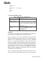
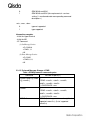
H18 AT Command User Manual Revision History
Version Content
1.00
Author
Kevin RY Cheng
Date
12/07/2009
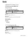
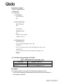
1 Introduction
1.1 Introduction to Interface between TE and MS
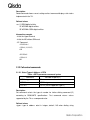
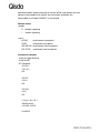
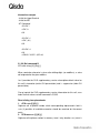
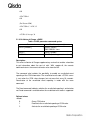
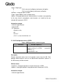
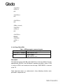
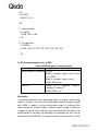
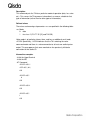
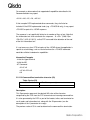
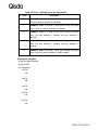
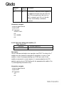
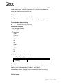
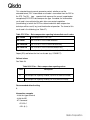
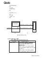
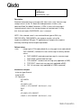
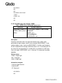
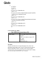
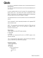
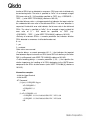
In order to communicate each other between TE and MS, we must use AT
commands. Figure 1.1 illustrates the interface. In section 2, we will divide the
content into ten subsections. They are about SIM, list management, mobility
management, call control, supplementary service, short message, cell
broadcast, base-band and the other service.
AT COMMAND
TE
MS
Figure 1.1
Explanation
ME
MS
TE
Mobile equipment
Mobile station. Basically, a mobile station is mobile
equipment with a SIM card.
Terminal Equipment that is the same as the controller in
this case.
Getting started
For testing AT commands, the MS can be connected to any computer
environment, as long as it has a V.24/V.28 serial interface. The commands can
be issued with, for example, HyperTerminal in Microsoft Windows or other
emulator programs.
Syntax description
The section gives a brief description of the syntax used for the command set.
The MS may echo characters received, depending on the setting of the
command E. As a default, echo is enabled, and characters are echoed at the
same rate, parity, and format as received.
The character defined by parameter S5 (default, BS, IRA 8) is interpreted as
request from the TE to delete the previous character.
<CR>
<LF>
Carriage return character, whose value is specified by
command S3, default IRA 13.
Line feed character, whose value is specified by
command S4, default IRA 10.
The name enclosed in angle brackets is a syntactical
<…>
element. The brackets do not appear in the command
line.
Strings enclosed in square brackets are optional items
[…]
(sub-parameters). The brackets do not appear in the
command line.
Other characters, including ‘?’,’=’, parentheses, etc, appear in commands and
response as written.
AT command syntax
A command line is made up of three elements: the prefix, the body and the
termination character. The command line prefix consists of the characters ‘AT’.
MS supports a set of commands referred to as basic syntax commands, and a
set of extended syntax commands, the latter prefixed with a plus sign (+).
Basic syntax command
The format of basic syntax commands, except for the command D, is as
follows:
<name>[<value>]
Example:
ATV1<CR> (set text form result codes)
<CR><LF>OK<CR><LF>(response)
Extended syntax command
+<name>[=<value>]
Example:
AT+CMUT=0<CR>( the representation of signal strength)
<CR><LF>OK<CR><LF>(response)
Test command syntax
+<name>=?
Example:
ATS3=?<CR>(show supported S3 values)
<CR><LF>S3: (0-127)<CR><LF>
<CR><LF>OK<CR><LF>
Read command syntax
+<name>?
Example:
AT+CACM?<CR>(show current accumulated call meter value)
<CR><LF>+CACM: ”0”<CR><LF>(response)
<CR><LF>OK<CR><LF>
If the indicated name is not recognized, an Error code is issued.
AT response syntax
The default response is text mode that is shown below. See the command V
for further details. The format of a response is as follows:
<CR><LF>[<response>]<CR><LF>
The <response> can be:
- Basic format result code, such as OK.
- Extended syntax result code, prefixed with a plus sign (+):
The result codes are separate by commas if it’s included several values. The
<value> followed by the colon is separated by a space. It is also possible that
result codes have no value. Unlike basic format result codes, extended syntax
result codes have no numeric equivalent, and are always issued in alphabetic
form.
There are two types of result code responses:
Final result code
A final result code indicates to the TE that execution of the command is
completed and another command may be issued.
If you typed an implemented AT command, you should get the result code OK.
If you typed an AT command that was not implemented, or which had the
wrong parameter or syntax, you will get the result code ERROR or else, for
example, +CME ERROR followed by an error code.
Unsolicited result code
Unsolicited result codes, such as RING, indicate the occurrence of an event
not directly associated with a command being issued from TE.
1.2 Initial the Test Environment
Initial the HyperTerminal.
- Start HyperTerminal
- Name a new connection
- Select the connection port
- Initial the connection port with 115200 bps and none flow control
Initial the MS.
- Put the SIM card into ME and power on the ME.
- Start all of AT Commands with “AT+CFUN=1”
- Camp on the cell with “AT+COPS=0”
2 Implemented AT commands for MS
2.1 Commands specified by GSM REC.27.07
2.1.1 General Commands
2.1.1.1 Request manufacturer identification +CGMI
Table: +CGMI parameter command syntax
Command
+CGMI
Possible response(s)
<manufacturer>
+CME ERROR: <err>
Description
Read handset or model’s manufacturer’s ID.
Defined values
<manufacturer>: total number of characters shall not exceed 2048.
Informative examples
-Initial the HyperTerminal
-Initial the MS
-AT Command
AT+CGMI<CR>
<manufacturer>
2.1.1.2 Request model identification +CGMM
Table: +CGMM parameter command syntax
Command
+CGMM
Possible response(s)
<model>
+CME ERROR: <err>
Description
Read model information which determined by ME manufacturer.
Defined values
<model id>: string type
Informative examples
- Initial the HyperTerminal
- Initial the MS without SIM card
- AT Command
AT+CGMM <CR>
H18
2.1.1.3 Request revision identification +CGMR
Table: +CGMR parameter command syntax
Command
+CGMR
Possible response(s)
<revision>
+CME ERROR: <err>
Description
Read revision of ME. It may include software and hardware revision.
Defined values
<revision >: information text
Informative examples
- Initial the HyperTerminal
- Initial the MS without SIM card
- AT Command
AT+CGMR<CR>
QisdaSWVer:H18_UNSIGNED_SW0.01,Build Info: M6260-KPRBL-1540,Boot
Block ver: 1,Build Data: Dec 04 2009, Build Time: 10:49:56
2.1.1.4 Request product serial number identification +CGSN
Table: +CGSN parameter command syntax
Command
Possible response(s)
+CGSN
<IMEI>
OK
+CME ERROR: <err>
Description
Read serial number identification which determined by ME manufacturer.
Defined values
<sn >: total number of characters shall not exceed 2048 characters.
Informative examples
- Initial the HyperTerminal
- Initial the MS without SIM card
- AT Command
AT+CGSN<CR>
359095000360270
OK
2.1.1.5 Select TE character set +CSCS
Table: +CSCS parameter command syntax
Command
Possible response(s)
+CSCS=[<chset>]
OK
ERROR
+CSCS?
+CSCS: <chset>
+CSCS=?
+CSCS: (list of supported <chset>s)
Description
Set command informs TA of which character set “<chset>” is used by the TE.
TA is then able to convert character strings correctly between TE and ME
character sets.
When TA-TE interface is set to 8-bit operation and used TE alphabet is 7 bit,
the highest bit shall be set to zero.
Read command returns the current setting and test command displays
conversion schemes implemented in the TA.
Defined values
<chset>: string type
Command
Possible response(s)
“IRA” (default)
International reference alphabet
“GSM”
GSM default alphabet
“UCS2”
16-bit universal multiple-octet coded character set; UCS2
character strings are converted to hexadecimal numbers
from 0000 to FFFF. ; e.g. “004100620063” equals three
16-bit characters with decimal values 65,98 and 99.
Informative examples
- Initial the HyperTerminal
- Initial the MS without SIM card
- AT Command
(1)
AT+CSCS=? <CR>
+CSCS: ("IRA","GSM","UCS2")
OK
(2)
AT+CSCS= “GSM”
+CSCS: “GSM”
OK
AT+CSCS? <CR>
+CSCS: “GSM”
OK
(3)
AT+CSCS ="GSM"
OK
AT+ CPBR =1,10
+CPBR: 1,"0920933828",129,"Tina"
+CPBR: 2,"+886227998800",145,"Qisda"
+CPBR: 3,"123456789",129,"test"
+CPBR: 4,"876425",129,"qwe"
+CPBR: 5,"7514876543",129,"afe"
OK
AT+CSCS ="UCS2"
OK
AT+CPBR =1,10
+CPBR: 1,"0920933828",129,"00540069006E0061"
+CPBR: 2,"+886227998800",145,"00420065006E0051"
+CPBR: 3,"123456789",129,"0074006500730074"
+CPBR: 4,"876425",129,"007100770065"
+CPBR: 5,"7514876543",129,"006100660065"
OK
2.1.1.6 Request international mobile subscriber identity +CIMI
Table: +CIMI parameter command syntax
Command
+CIMI
Possible response(s)
<IMSI>
OK
+CME ERROR:<err>
Description
Execution command causes the TA to return <IMSI>, which is intended to
permit the TE to identify the individual SIM that is attached to ME.
Defined values
<IMSI>: International Mobile Subscriber Identity (string without double quotes)
Informative examples
- Initial the HyperTerminal
- Initial the MS
- AT Command
AT+CIMI
466880100493652
OK
2.1.1.7 PCCA STD-101[17] select wireless network +WS46
Table: +WS46 parameter command syntax
Command
Possible response(s)
+WS46=[<n>]
OK
+WS46?
+WS46: <n>
+WS46=?
(list of supported <n>s)
Description
Read command shows current setting and test command displays side stacks
implemented in the TA.
Defined values
<n>:12 GSM digital cellular
22 WCDMA digital cellular
25 WCDMA+GSM digital cellular
Informative example
- Initial the HyperTerminal
- Initial the MS without SIM card
- AT Command
AT+WS46=?
+WS46: (12,22,25)
OK
AT+WS46?
+WS46: 12
OK
2.1.2 Call control commands
2.1.2.1 Select Type of Address +CSTA
Table: +CSTA parameter command syntax
Command
Possible response(s)
+CSTA=<type>
OK
+CSTA?
+CSTA: <type>
+CSTA=?
+CSTA: (list of supported <type>s)
Description
Set command selects the type of number for further dialing command (D)
according to GSM/UMTS specifications. Test command returns values
supported by the TA as a compound value.
Defined values
<type>: type of address octet in integer; default 145 when dialing string
includes international access code character “+”, otherwise 129.
Informative examples
- Initial the HyperTerminal
- Initial the MS
- AT Command
AT+CSTA=?
+CSTA: (129,145)
OK
AT+CSTA?
+CSTA: 129
OK
AT+CSTA=145
OK
AT+CSTA?
+CSTA: 145
OK
2.1.2.2 Call mode +CMOD
Table: +CMOD parameter command syntax
Command
Possible response(s)
+CMOD=[<mode>]
OK
+CMOD?
+CMOD: <mode>
+CMOD=?
+CMOD: (list of supported <mode>s)
Description
Set command selects the call mode of further dialing commands (D) or for next
answering command (A). Mode can be either single or alternating. Test
command returns values supported by the TA as a compound value.
Defined values
<mode>: 0 single mode
Informative examples
- Initial the HyperTerminal
- Initial the MS
- AT Command
AT+CMOD=?
+CMOD: (0)
OK
AT+CMOD?
+CMOD: 0
OK
2.1.2.3 Hang up call +CHUP
Table: +CHUP parameter command syntax
Command
Possible response(s)
+CHUP
OK
+CHUP=?
OK
Description
Execution command causes the TA to hang up the current GSM/UMTS call of
the ME.
2.1.2.4 Select bearer service type +CBST
Table: +CBST parameter command syntax
Command
Possible response(s)
+CBST=[speed>[,<name>
[,<ce>]]]
+CBST?
+CBST: <speed>,<name>,<ce>
+CBST=?
+CBST: (list of supported <speed>s),(list of
supported <name>s), (list of supported <ce>s)
Description
Set command selects the bearer service <name> with data rate <speed>, and
the connection element <ce> to be used when data calls are originated. Values
may also be used during mobile terminated data call setup, especially in case
of single numbering scheme calls.
Test command returns values supported by the TA as compound values.
Defined values
<speed> (in bps):
0 – autobaud
7 – 9600 (V.32)
12 – 9600 (V.34)
14 – 14400 (V.34)
16 – 28800 (V.34)
17 – 33600 (V.34)
39 – 9600 (V.120)
43 – 14400 (V.120)
48 – 28800 (V.120)
51 – 48000 (V.120)
71 – 9600 (V.110)
75 – 14400 (V.110)
80 – 28800 (V.110)
81 – 38400 (V.110)
83 – 56000 (X.31 flag stuffing, UDI/RDI)[see note]
84 – 64000 bps (X.31 flag stuffing, UDI)[see note]
116 – 64000 bps
134 – 64000 bps(multimedia)
<name>:
0 – Data circuit asynchronous
1 – Data circuit synchronous
4 – Data circuit asynchronous (RDI)
<ce>:
0 – Data transparent
1 – Data nontransparent
Note: this setting can be used in conjunction with asynchronous
nontransparent UDI/RDI service in order to get Frame Tunneling
mode
Informative examples
- Initial the HyperTerminal
- Initial the MS
- AT Command
AT+CBST=?
CBST: (0,7,12,14,16,17,39,43,48,51,71,75,80,81,83,84,116,134),(0,1,4),(0,1)
OK
AT+CBST?
+CBST: 0,0,1
OK
2.1.2.5 Radio link protocol +CRLP
Table: +CRLP parameter command syntax
Command
Possible response(s)
+CRLP=[<iws>[,<mws>[,<
T1>[,<N2>]]]
+CRLP=?
+CRLP: <iws>,<mws>,<T1>,<N2>
[<CR><LF>+CRLP:<iws>,<mws>,<T1>,<N2>
[…]]
+CRLP=?
+CRLP: (list of supported <iws>s), (list of
supported <mws>s), (list of supported <T1>s),
Description
Radio link protocol (RLP) parameters used when non-transparent data calls
are originated may be altered with set command. Available command
sub-parameters depend on the RLP versions implemented by the device
(currently version 0,1(default), 2 are supported).
Read command returns current setting for supported RLP version. Test
command returns values supported by the TA as a compound value.
Defined values
<iws>: IWF to MS window size
<mws>: MS to IWF window size
<T1>: acknowledgement timer, in units of 10 ms.
<N2>: retransmission attempts
For Version 0 and 1, the following parameter values are supported:
<iws> – 0 to 61 frames
<mws> – 0 to 61 frames
<T1> – 38 to 255 x 10 ms
<N2> – 1 to 255 retransmits
For Version 2, the following parameter values are supported:
<iws> – 0 to 488 frames
<mws> – 0 to 488 frames
<T1> – 42 to 255 x 10 ms
<N2> – 1 to 255 retransmits
Informative examples
-Initial the HyperTerminal
-Initial the MS
-AT Command
AT+CRLP =?
+CRLP: (0-61),(0-61),(38-255),(1-255),0
+CRLP: (0-61),(0-61),(38-255),(1-255),1
+CRLP: (0-488),(0-488),(42-255),(1-255),2
OK
AT+CRLP?
+CRLP: 61,61,48,6,0
+CRLP: 0,0,38,1,1
+CRLP: 240,240,52,6,2
OK
2.1.2.6 Service reporting control +CR
Table: +CR parameter command syntax
Command
Possible response(s)
+CR=[<mode>]
OK
+CR?
+CR: <mode>
+CR=?
+CR: (list of supported <mode>s)
Description
Set command controls whether or not intermediate result code +CR: <serv> is
returned from the TA to the TE. If enabled, the intermediate result code is
transmitted at the point during connect negotiation at which the TA has
determined which speed and quality of service will be used, before any error
control or data compression reports are transmitted, and before the
intermediate result code CONNECT is transmitted.
Defined values
<mode> :
0 disables reporting
1
enables reporting
<serv>:
ASYNC
SYNC
REL ASYNC
REL SYNC
asynchronous transparent
synchronous transparent
asynchronous non-transparent
synchronous non-transparent
Informative examples
- Initial the HyperTerminal
- Initial the MS
- AT Command
AT+CR=?
+CR: (0,1)
OK
AT+CR?
+CR: 0
OK
AT+CR=1
+CR:1
OK
/* Setup a data call */
ATD024496688;
+CR: REL ASYNC
CONNECT
2.1.2.7 Extended error report +CEER
Table: +CEER parameter command syntax
Command
+CEER
Possible response(s)
+CEER: <report>
Description
Execution command causes the TA to return one or more lines of information
text <report>, determined by the ME manufacturer, which should offer the user
of the TA an extended report of the reason for
- the failure in the last unsuccessful call setup or in-call modification;
- the last call releases;
Typically, the text will consist of a single line containing the cause Information
given by GSM/UMTS network in textual format.
Defined values
<report>: the total number of characters shall not exceed 2041 characters. See
Section 0 for more information of <report>. Or see 3GPP TS 24.008.
Informative examples
- Initial the HyperTerminal
- Initial the MS
- AT Command
AT+CEER
+CEER: No cause information available
OK
ATD0920933828;
OK
AT+CHUP
OK
AT+CEER
+CEER: Client ended call
OK
2.1.2.8 Cellular result codes +CRC
Table: +CRC parameter command syntax
Command
Possible response(s)
+CRC=[<mode>]
+CRC?
+CRC: <mode>
+CRC=?
+CRC: (list of supported <mode>s)
Description
Set command controls whether or not the extended format of incoming call
indication is used. When enabled, an incoming call is indicated to the TE with
unsolicited result code +CRING: <type> instead of the normal RING.
Test command returns values supported by the TA as a compound value.
Defined values
<mode> :
0 disables extended format
1 enables extended format
<type>
ASYNC
SYNC
REL ASYNC
REL SYNC
FAX
VOICE
VOICE/XXX
asynchronous transparent
synchronous transparent
asynchronous non-transparent
synchronous non-transparent
facsimile (TS 62)
normal voice (TS 11)
voice followed by data (BS81) (XXX is ASYNC, SYNC,
REL ASYNC or REL SYNC)
ALT VOICE/XXX alternating voice/data, voice first (BS 61)
ALT XXX/VOICE alternating voice/data, data first (BS 61)
ALT VOICE/FAX alternating voice/fax, voice first (TS 61)
ALT FAX/VOICE alternating voice/fax, fax first (TS 61)
GPRS <PDP_type>, <PDP_addr>[,[<L2P>][,<APN>]] GPRS network request
for PDP context activation
<PDP_type>, <PDP_addr> and <APN> are as defined in the Define PDP
Context (+CGDCONT) command. The optional <L2P> proposes a layer 2
protocol to use between the MT and the TE. It is defined in the Enter GPRS
Data Mode (+CGDATA) command.
Informative example
- Initial the HyperTerminal
- Initial the MS
- AT Command
AT+CRC?
+CRC: 0
OK
AT+CRC=?
+CRC: (0,1)
OK
AT+CRC=1
OK
+CRING: VOICE (MT call)
2.1.2.9 Dial command D
ATD<dial string>[I/I] [G/g] [;]
When semicolon character is given after dialing digits (or modifiers), a voice
call originated to the given address.
I or I (override the CLIR supplementary service subscription default value for
this call; I=invocation (restrict CLI presentation) and i = suppression (allow CLI
presentation).
G or g (control the CUG supplementary service information for this call; uses
index and info values set with command +CCUG.
Direct dialing from phonebooks
1. ATD><str>[I] [G] [;]
Originate call to phone number which corresponding alphanumeric field is
<str> (if possible, all available memories should be searched for the correct
entry).
2. ATD>mem<n> [I] [G] [;]
Originate call to phone number in memory “mem” entry location <n> (mem is
“SM”, “LD”, “MC”, “ME”, “RC”, “MT” or “SN”. Available memories may be
queried with Select Phonebook Storage test command +CPBS=? )
3. ATD><n> [I] [G] [;]
Originate call to phone number in entry location <n> (it is manufacturer specific
which memory storage of ME, SIM/UICC and TA is used; command Select
Phonebook Memory Storage +CPBS setting is recommended to be used).
Informative examples
- Initial the HyperTerminal
- Initial the MS
- Initial the alpha id of first physical record in AND is “A”
- AT Command
(1) Dial number 188
ATD188;
OK
(2) Dial number in phonebook index 6.
AT+CPBS?
+CPBS: "SM",37,100
OK
ATD>SM6;
OK
2.1.3 Network service related commands
2.1.3.1 Subscriber number +CNUM
Table: +CNUM parameter command syntax
Command
+CNUM
Possible response(s)
[+CNUM: [<alpha1>],<number1>, <type1>
[…<CR><LF>+CNUM: [alphaX>],<numberX>, <typeX>]]
OK
+CME ERROR:<err>
Description
Set command returns the MSISDN related to the subscriber (this information
can be stored in the SIM or in the ME.) If subscriber has different MSISDN for
different services, each MSISDN is returned in a separate line (<CR><LF>).
Defined values
<number>: string type; phone number
<alpha>: string type; optional alphanumeric string associated with
<number>: used character set should be the one selected with command
Select TE Character Set +CSCS.
<type>: integer value
129
145
National
International
Informative examples
- Initial the HyperTerminal
- Initial the MS
- AT Command
(1) Power on MS but SIM is not ok
AT+CPIN?
+CME ERROR: 10
AT+CNUM
+CME ERROR: 10
(2) Power on MS and SIM is ok
AT+CPIN?
+CPIN: READY
OK
AT+CNUM
+CNUM: “ABC”,”0920123456”,129
OK
(3) Write record
AT+CPBS="ON"
OK
AT+CPBW=1,"0960530355",,"WM0"
OK
AT+CPBR=1
+CPBR: 1,"0960530355",129,"WM0"
OK
AT+CNUM
+CNUM: "WM0","0960530355",129
OK
2.1.3.2 Network registration +CREG
Table: +CREG parameter command syntax
Command
Possible response(s)
+CREG=[<n>]
+CME ERROR:<err>
+CREG?
+CREG: <n>,<stat>
+CME ERROR:<err>
+CREG=?
+CREG: (list of supported <n>s)
Description
Set command controls the presentation of an unsolicited result code code
+CREG: <stat>when <n>=1.
Read command returns the status of result code presentation and an integer
<state> which shows whether the network has currently indicated the
registration of the ME.
Test command returns a list of supported <n>.
Defined values
<n>: integer value
0 <default>
Disable network registration unsolicited result code.
1
Enable network registration unsolicited result code
+CREG: <stat>.
<state>: integer value
0
Not registered, ME is not currently searching a new
operator to register to (NO SERVICE)
1
Registered, home network
2
Limiting Service: not registered but ME is currently
searching a new operator to register to
3
Limiting Service: registration denied
4
5
Unknown
Registered, roaming
Informative examples
- Initial the HyperTerminal
- Initial the MS
- AT Command
(1) Disable network registration unsolicited result code
AT+CREG=0
OK
(2) Enable network registration unsolicited result code
AT+CREG=1
OK
(3) Returns the status of current network registration.
AT+CREG?
+CREG: 1,1
OK
(4) Query all status:
AT+CREG=?
+CREG: (0-1)
OK
2.1.3.3 Operator selection +COPS
Table: +COPS parameter command syntax
Command
Possible response(s)
+COPS=[<mode>[,<forma +CME ERROR: <err>
t>
[,<oper>[,< AcT>]]]]
+COPS?
1) +COPS: <mode>[,<format>,<oper>[,<
AcT>]]
2) +CME ERROR: <err>
+COPS=?
1) +COPS: [list of supported (<stat>,long
alphanumeric <oper>
,short alphanumeric <oper>,numeric <oper>[,<
AcT>])s]
[,,(list of supported <mode>s),(list of supported
<format>s)]
2) +CME ERROR: <err>
Description
Set command forces an attempt to select and register the GSM/UMTS network
operator. <mode> is used to select whether the selection is done automatically
by the MT or is forced by this command to operator <oper> (it shall be given in
format <format>) to a certain access technology, indicated in <AcT>. If the
selected operator is not available, no other operator shall be selected (except
<mode>=4). If the selected access technology is not available, then the same
operator shall be selected in other access technology. The selected operator
name format shall apply to further read commands (+COPS?) also. <mode>=2
forces an attempt to deregister from the network. The selected mode affects to
all further network registration (e.g. after <mode>=2, MT shall be unregistered
until <mode>=0 or 1 is selected). Refer subclause 9.2 for possible <err>
values. This command should be abortable when registration/deregistration
attempt is made.
Read command returns the current mode, the currently selected operator and
the current Access Technology. If no operator is selected, <format>, <oper>
and < AcT> are omitted.
Test command returns a set of five parameters, each representing an operator
present in the network. A set consists of an integer indicating the availability of
the operator <stat>, long and short alphanumeric format of the name of the
operator, numeric format representation of the operator and access technology.
Any of the formats may be unavailable and should then be an empty field. The
list of operators shall be in order: home network, networks referenced in SIM or
active application in the UICC (GSM or USIM) in the following order: HPLMN
selector, User controlled PLMN selector, Operator controlled PLMN selector
and PLMN selector (in the SIM or GSM application), and other networks.
It is recommended (although optional) that after the operator list TA returns
lists of supported <mode>s and <format>s. These lists shall be delimited from
the operator list by two commas.
NOTE: The access technology selected parameters, <AcT>, should only be
used in terminals capable to register to more than one access technology.
Selection of <AcT> does not limit the capability to cell reselections, even
though access technology is selected, the phone may still re-select a cell in
other access technology.
Defined values
<mode>: integer value
0
automatic (<oper> field is ignored)
1
manual (<oper> field shall be present, and <AcT>
optionally)
2
deregister from network
3
set only <format> (for read command +COPS?), do not
attempt registration/deregistration (<oper> and < AcT>
4
fields are ignored); this value is not applicable in read
command response
manual/automatic (<oper> field shall be present); if
manual selection fails, automatic mode (<mode>=0) is
entered
<format>: integer value
0
long format alphanumeric <oper>
1
short format alphanumeric <oper>
2
numeric <oper>
<oper>: string type; <format> indicates if the format is alphanumeric or
numeric; long alphanumeric format can be upto 16 characters long and short
format up to 8 characters (refer GSM MoU SE.13 [9]); numeric format is the
GSM Location Area Identification number (refer TS 24.008 [8] subclause
10.5.1.3) which consists of a three BCD digit country code coded as in ITU-T
E.212 Annex A [10], plus a two BCD digit network code, which is
administration specific; returned <oper> shall not be in BCD format, but in IRA
characters converted from BCD; hence the number has structure: (country
code digit 3)(country code digit 2)(country code digit 1)(network code digit
3)(network code digit 2)(network code digit 1)
<state>: integer value
0
unknown
1
available
2
3
current
forbidden
<AcT>: integer value
0
GSM only
2
WCDMA only
Informative examples
- Initial the HyperTerminal
- Initial the MS
- AT Command
(1) network connection
--GSM only
AT+COPS=0,,,0
ERROR
--WCDMA only
AT+COPS=0,,,2
OK
AT+ WS46?
+WS46: 22
OK
-- WCDMA and GSM
AT+COPS=0
OK
AT+ WS46?
+WS46: 25
OK
AT+COPS?
+COPS: 0,0,"Far EasTone Tele",2
OK
(2) List all available network and manual selection of network
AT+COPS=?
+COPS: (1,"Far EasTone Tele","Far EasT","46601",0),(2,"Far EasTone
Tele","Far EasT","46601",2),(1,"KG
Telecom","KGT","46688",0),(3,"Taiwan Cellular
","TWNGSM","46697",2),(3,"Chunghwa
Telecom","Chunghwa","46692",2),(3,"","","46689",2),(3,"Chunghwa
Telecom","Chunghwa","46692",0),(3,"Taiwan Cellular
","TWNGSM","46697",0),,(0,1,3,4),(0,1,2)
OK
AT+COPS=1,2,"46692",0
OK
2.1.3.4 Facility Lock AT+CLCK
Table: +CLCK parameter command syntax
Command
Possible response(s)
+CLCK=<fac>,<mode>[,< Right: OK
passwd>]
When <mode>=2 and command successful:
Right: +CLCK: <status>[,<class>]
Wrong: +CME ERROR: <er>
+CLCK=?
+CLCK: (list of supported <fac>s)
+CME ERROR: <err>
Description
Execution command is used to lock, unlock or interrogate a ME or a network
facility <fac>. Password is normally needed to do such actions. When querying
the status of a network service (<mode>=2) the response line for ‘not active’
case (<status>=0) should be returned only if service is not active for any
<class>. This command should be abortable when network facilities are set or
interrogated.
Call barring facilities are based on GSM supplementary services. The
interaction of these with other commands based on other GSM supplementary
services is described in the GSM standard.
Test command returns facility values supported by the TA as compound value.
Defined Values
<fac>:
“AB” All Barring services
“AC” All incoming barring services
“AG” All outgoing barring services
“AI” BAIC (Barr All Incoming Calls)
“AO” BAOC (Barr All Outgoing Calls)
“IR” BIC-Roam (Barr Incoming Calls when Roaming outside the home
country)
“OI” BOIC (Barr Outgoing International Calls)
“OX” BOIC-exHC (Barr Outgoing International Calls except to Home Country)
“SC” PIN enabled (<mode>=1) / disabled (<mode> = 0)
“PN” Network personalization of the ME
“PU” Network subset personalization of the ME
“PP” Service provider personalization of the ME
“PC” Corporate personalization of the ME
“PF” Personalization on first inserted SIM
<mode>:
0
1
2
Unlock
Lock
Query status
<status>:
0
1
Not active
Active
<password>: string type, indicate PIN or network password
<class>: integer type, sum of integers each representing a class(default 7)
1
Voice
2
4
Data
Fax
8
Short message
16
32
Data circuit sync
Data circuit async
64
128
Dedicated packet access
Dedicated PAD access
Informative examples
-Initial the HyperTerminal
-Initial the MS
-AT Command
AT+CLCK=?
+CLCK:
("AB","AC","AG","AI","AO","IR","OI","OX","SC","PN","PU","PP","PC","PF
")
OK
(1) Enable PIN with “1234”
AT+CLCK=”SC”,1,”1234”
OK
(2) Disable PIN
AT+CLCK=”SC”,0,”1234”
OK
(3) Query the PIN lock status
AT+CLCK=”SC”,2
+CLCK: 0
OK
(4) Activate all outgoing calls barring
AT+CLCK=”AO”,1,”1234”
OK
(5) Disable all outgoing calls barring
AT+CLCK=”AO”,0,”1234”
OK
2.1.3.5 Change password +CPWD
Table: +CPWD action command syntax
Command
Possible response(s)
+CPWD=<fac>, <oldpwd>, <newpwd>
+CME ERROR: <err>
+CPWD=?
+CPWD:
list
of
supported
(<fac>, <pwdlength>)s
+CME ERROR: <err>
Description
Action command sets a new password.
Defined values
<fac>:
“AB” All Barring services
“SC” PIN enabled (<mode>=1) / disabled (<mode> = 0)
“P2” SIM PIN2
<oldpwd>, <newpwd>: string type; <oldpwd> shall be the same as password
specified for the facility from the ME user interface or with command Change
Password +CPWD and <newpwd> is the new password; maximum length of
password can be determined with <pwdlength>
<pwdlength>: integer type maximum length of the password for the facility
Informative examples
- Initial the HyperTerminal
- Initial the MS
- AT Command
AT+CPWD=?
+CPWD: ("AB",4),("SC",8),("P2",8)
OK
2.1.3.6 Calling line identification presentation +CLIP
Table: +CLIP parameter command syntax
Command
Possible response(s)
+CLIP=[<n>]
+CLIP?
+CLIP: <n>, <m>
+CLIP=?
+CLIP:(list of supported <n>)
Description
This command enables a called subscriber to get the calling line identity (CLI)
of the calling party when receiving a mobile terminated call.
Defined values
<n>: integer type, sets /shows the result code presentation status in TA
0
1
Disable
Enable
<m>: integer type, shows the subscriber CLIP service status in the network
0
1
CLIP not provisioned
CLIP provisioned
2
Unknown (e.g. no network, etc.)
Informative examples
- Initial the HyperTerminal
- Initial the MS
- AT Command
(1) ACTIVATE
AT+CLIP=1
OK
AT+CLIP?
+CLIP: 1, 1
(As incoming call occurs, ms will display the unsolicited result code.)
RING
(1)+CLIP: "0920123456",129,"",,"APPLE",0 (AT+CSCS=”IRA”)
(2)+CLIP: "",128,,,,1
(2) DEACTIVATE
AT+CLIP=0
OK
AT+CLIP?
+CLIP:0,1
(3) INTERROGATION
AT+CLIP?
+CLIP: 0,1
OK
2.1.3.7 Call line identification restriction +CLIR
Table: +CLIR parameter command syntax
Command
Possible response(s)
+CLIR=[<n>]
+CLIR?
+CLIR: <n>, <m>
+CLIR=?
+CLIR:(list of supported <n>)
Description
This command allows a calling subscriber to enable or disable the presentation
of the CLI to the called party when originating a call. Set command overrides
the CLIR subscription (default is restricted or allowed) when temporary mode
is provisioned as a default adjustment for all following outgoing calls. This
adjustment can be revoked by using the opposite command. Read command
gives the default adjustment for all outgoing calls (given in <n>), and also
triggers an interrogation of the provision status of the CLIR service (given in
<m>). Test command returns values supported by the TA as a compound
value.
Defined values
<n>: integer type, sets the adjustment for outgoing call
0
Presentation indicator is used according to CLIR service
1
CLIR invocation
2
CLIR suppression
<m>: integer type, shows the subscriber CLIR service status in the network
0
CLIR not provisioned
1
CLIR provisioned
2
Unknown (e.g. no network, etc.)
3
CLIR temporary mode presentation restricted
4
CLIR temporary mode presentation allowed
Informative examples
- Initial the HyperTerminal
- Initial the MS
- AT Command
(1) DEACTIVATE
AT+CLIR=2
OK
ATD<phone num>; (CLIR suppression, the called party will receive the
calling number.)
OK
(2) ACTIVATE
AT+CLIR=1
OK
ATD<phone num>; (CLIR invocation, the called party will not receive the
calling number.)
After invocation of the CLIR, the called party will not receive the calling
subscriber’s phone number.
(3) INTERROGATION
AT+CLIR?
+CLIR: 0,4
OK
It means the current setting is according to the subscription of the CLIR
service. And the service status in the network is “Temporary mode
presentation allowed”.
2.1.3.8 Connected line identification presentation +COLP
Table: +COLP parameter command syntax
Command
Possible response(s)
+COLP=[<n>]
+COLP?
+COLP: <n>, <m>
+COLP=?
+COLP:(list of supported <n>s)
Description
This command enables a calling subscriber to get the connected line identity
(COL) of the called party after setting up a mobile originated call. The
command enables or disables the presentation of the COL at the TE. It has no
effect on the execution of the supplementary service COLR in the network.
This command is useful for call forwarding of the connected line.
When enabled (and called subscriber allows),
+COLP: <number>, <type>[, <subaddr>, <satype>[, <alpha>]] intermediate
result code is returned from TA to TE before any +CR or V.25ter response. It is
manufacturer specific if this response is used when normal voice call is
established.
Read command gives the status of <n>, and also triggers an interrogation of
the provision status of the COLP service (given in <m>).
Define values
<n>(parameter sets/shows the result code presentation status in the TA)
0
Disable
1
Enable
<m>(parameter shows the subscriber COLP service status in the network)
0
COLP not provisioned
1
COLP provisioned
2
Unknown (e.g. no network, etc.)
Informative examples
- Initial the HyperTerminal
- Initial the MS
- AT Command
AT+COLP=?
+COLP: (0,1)
OK
AT+COLP?
+COLP: 0,0
OK
AT+COLP=1
OK
ATD0920123456;
+COLP: ,255,,,"LIN"
OK
2.1.3.9 Closed user group +CCUG
Table: +CCUG parameter command syntax
Command
Possible response(s)
+CCUG=[<n>[, <index>[, <info>]]]
+CCUG?
+CCUG: <n>,<index>, <info>
Description
This command allows control of the Closed User Group supplementary service.
Set command enables the served subscriber to select a CUG index to
suppress the Outgoing Access (OA), and to suppress the preferential CUG.
Define values
<N>
0
1
<Index>
0…9
10
<Info>
0
1
2
3
Disable CUG temporary mode
Enable CUG temporary mode
CUG index
No index (preferred CUG taken from subscriber data.
No information
Suppress OA
Suppress preferential CUG
Suppress OA and preferential CUG
Informative examples
- Initial the HyperTerminal
- Initial the MS
- AT Command
AT+CCUG=?
OK
AT+CCUG?
+CCUG: 0,0,0
OK
2.1.3.10 Call forwarding service +CCFC
Table: +CCFC parameter command syntax
Command
Possible response(s)
+CCFC =<reason>,
+CME ERROR: <err>
<mode>[, <number>[,
When <mode> = 2 and command successful:
<type>[,<class>[,<subadd +CCFC: <status>, <class1>[, <number>,
r>[, <satype>[, <time>]]]]]] <type>[,<subaddr>,<satype>[,<time>]]][<CR><
LF>+CCFC: <status>, <class2>[, <number>,
<type>[, <subaddr>, <satype>[, <time>]]]
[…]]
+CCFC=?
+CCFC: (list of supported <reason>s)
Description
This command allows control of the call forwarding supplementary service.
Registration, erasure, activation, deactivation, and status query are supported.
Defined values
<Reason>:
0
1
2
3
4
5
Unconditional
Mobil busy
No Reply
Not reachable
All call forwarding
All conditional call forwarding
<Mode>:
0
1
2
3
4
Disable
Enable
Query Status
Registration
Erasure
<Class x>: integer type, sum of bearer service code.
1
Voice (telephony)
Data (refers to all bearer services; with <mode>=2 this
2
may refer only to some bearer service if TA does not
support values 16,32,64 and 128)
4
Fax (facsimile services)
8
Short message service
16
Data circuit sync
32
64
Data circuit async
Dedicated packet access
128
Dedicated PAD access
255
All type
<number>: string type, forwarding phone number.
<type>: type of address octet in integer format; default 145 when dialing string
includes international access code character “+”, otherwise 129
<subaddr>: string type subaddress of format specified by <satype>
<satype>: type of subaddress octet in integer format; default 128
<Time>: 1…30 when “no reply” is enabled or queried, this gives the time in
seconds to wait before call is forwarded, default value 20
<Status>:
0
Not active
1
Active
Informative examples
- Initial the HyperTerminal
- Initial the MS
- AT Command
(1) Query status
AT+CCFC=0,2
Query the status of unconditional forwarding
+CCFC: 0,255
Interrogated result: not active, voice
OK
(2) Registration
Before enable, disable, and erasure, you should register the SS service.
AT+CCFC=0,3,”0123456789”
Register unconditional forwarding to “0123456789” and activated the
service.
OK
It doesn’t means that the SS service is registered successfully. You should
query the status to confirm the result.
AT+CCFC=0,2
+CCFC: 1,1," 0123456789",129,,,
OK
(3) Deactivate
AT+CCFC=0,0
Disable unconditional forwarding.
OK
(4)Activate
AT+CCFC=0,1
Enable unconditional forwarding.
(5) Erasure
AT+CCFC=0,4
Erase registered unconditional forwarding data.
Note: After registering unconditional call forwarding, one can't register
another reason’s service.
2.1.3.11 Call waiting service +CCWA
Table: +CCWA parameter command syntax
Command
Possible response(s)
+CCWA =[<n>[, <mode>[, +CME ERROR: <err>
<class>]]]
When <mode> = 2 and command successful
+CCWA:
<status>,<class1>[<CR><LF>+CCWA:
<status>, <class2>[…]]
+CCWA?
+CCWA: <n>
+CCWA=?
+CCWA: (list of supported <n>s)
Description
This command allows control of the Call Waiting supplementary service.
Activation, deactivation and status query are supported. When querying the
status of a network service (<mode>=2) the response line for ‘not active’ case
(<status>=0) should be returned only if services not active for any <class>.
Parameter <n> is used to disable/enable the presentation of an unsolicited
result code +CCWA: <number>, <type>, <class>,[<alpha>][,<CLI validity>] to
the TE when call waiting service is enabled. Command should be abortable
when network is interrogated.
Defined values
<N>: integer type (sets/shows the unsolicited result code presentation status in
the TA),
.
0
Disable
1
Enable
<Mode>: integer type, operation mode of
0
Disable
1
Enable
2
Query status
<Status>: integer type, CCWA status.
0
Not active
1
Active
<Class>: is a sum of integers each representing a class of information
1
Voice
2
Data (refers to all bearer services; with <mode>=2 this
may refer only to some bearer service if TA does not
support values 16,32,64 and 128)
4
Fax (facsimile services)
8
Short message service
16
Data circuit sync
32
Data circuit async
64
Dedicated packet access
128
Dedicated PAD access
255
All type
<Number>: string type phone number of calling address in format specified by
<type>
<Type>: type of address octet in integer format
<Alpha>:optional string type alphanumeric representation of <number>
corresponding to the entry found in phonebook.
<CLI validity>:
0
CLI valid
1
CLI has been withheld by the originator.
2
CLI is not available due to interworking problems or
limitations of originating network.
Informative examples
- Initial the HyperTerminal
- Initial the MS
- AT Command
(1) ACTIVATION
AT+CCWA=0,1
OK
(2) DEAACTIVATION
AT+CCWA=0,0
OK
AT+CCWA=1
ATD0952123456;
OK
(Another call is coming)
+CCWA: , 161,1,,1
(3) INTERROGATION
AT+CCWA=0,2
Case 1: if the call waiting is active, echo
+CCWA: 1,1
Case 2: if operation success and call waiting is not active, echo
+CCWA: 0,1
Case 3: if operation success and network not support, echo
ERROR
2.1.3.12 Short string procedure AT+CHLD
Table: +CHLD parameter command syntax
Command
Possible response(s)
+CHLD =[<n>]
+CME ERROR <err>
+CHLD=?
[+CHLD: (list of supported <n>s)
Description
This command allows the control of the following call related services:
-
a call can be temporarily disconnected from the ME but the connection is
retained by the network;
-
Multiparty conversation (conference calls);
-
The served subscriber who has two calls (one held and the other either
active or alerting) can connect the other parties and release the served
subscriber’s own connection.
Calls can be put on hold, recovered, released, added to conversation, and
transferred similarly.
It is recommended (although optional) that test command returns a list of
operations which are supported. The call number required by some operations
shall be denoted by "x" (e.g. +CHLD: (0,1,1x,2,2x,3)).
Defined values
1. AT+CHLD=0
Release all held calls or waiting calls.
2. AT+CHLD=1
Release all active calls and accept the other held or waiting calls.
3. AT+CHLD=1x
Release a specified active call x.
4. AT+CHLD=2
Place all active calls on hold and accept the other waiting or held calls.
5. AT+CHLD=2x
Place all active calls on hold except call x with which communication shall be
supported.
6. AT+CHLD=3
Adds held calls to the conversation.
7. AT+CHLD=4
Connects the two calls and disconnects the subscriber from both calls.
Informative examples
- Initial the HyperTerminal
- Initial the MS
- AT Command
(1)
;;;;;;MO1<Test Module> makes a call to MT1
ATD0921214863;
OK
;;;;;;MT1 accepts the call from MO1
AT+CHLD=2
OK
;;;;;;MO2 makes a call to MO1
;;;;;;MO1 accepts the call from MO2
Ring
ATA
AT+CHLD=1
OK
;;;;;;MO1-MO2 breaks.
(2)
;;;;;;MO1<Test Module> makes a call to MT1
ATD0921214863;
OK
;;;;;;MT1 accepts the call from MO1
AT+CHLD=2
OK
;;;;;;MO2 makes a call to MO1
;;;;;;MO1 accepts the call from MO2
Ring
ATA
AT+CHLD=4
OK
;;;;;;Both calls break.
2.1.3.13 Unstructured supplementary service data +CUSD
Table: +CUSD parameter command syntax
Command
Possible response(s)
+CUSD=[<n>[, <str>[, <dcs>]]]
+CME ERROR: <err>
+CUSD?
+CUSD: <n>
+CUSD=?
+CUSD: (list of supported <n>s)
Description
This command allows control of the Unstructured Supplementary Service Data
(USSD). Both network and mobile initiated operations are supported.
Parameter <n> is used to disable/enable the presentation of an unsolicited
result code (USSD response from the network, or network initiated operation)
+CUSD: <m>[, <str>, <dcs>] to the TE. In addition, value <n>=2 is used to
cancel an ongoing USSD session.
When <str> is given, a mobile initiated USSD-string or a response
USSD-string to a network initiated operation is sent to the network. The
response USSD-string from the network is returned in a subsequent
unsolicited +CUSD result code.
Test command returns values supported by the TA as a compound value.
Defined values
<n>
0
1
2
Disable the result code presentation in the TA
Enable the result code presentation in the TA
Cancel session (not applicable to read command
response)
<str>: string type USSD-string(when <str> parameter is not given, network is
not interrogated).
<dcs>: Cell Broadcast Data Coding Scheme in integer format.
<M>
0
no further user action required
1
further user action required.
2
USSD terminated by network
3
Other local client has responded
4
Operation not supported
5
Network time out
Informative examples
- Initial the HyperTerminal
- Initial the MS
- AT Command
AT+CUSD=?
+CUSD: (0-2)
OK
AT+CUSD?
+CUSD: 0
OK
AT+CUSD=1
OK
(Far Eastone SIM)
AT+CUSD=1,"*147#",15
OK
+CUSD: 0,"Accepte",0
2.1.3.14 Advice of Charge +CAOC
Table: +CAOC parameter command syntax
Command
Possible response(s)
+CAOC=[<mode>]
[+CAOC: <ccm>]
+CME ERROR: <err>
+CAOC?
+CAOC: <mode>
+CAOC=?
[+CAOC: (list of supported <mode>s)]
Description
This refers to Advice of Charge supplementary service that enables subscriber
to get information about the cost of calls. With <mode>=0, the execute
command returns the current call meter value from the ME.
The command also includes the possibility to enable an unsolicited event
reporting of the CCM information. The unsolicited result code +CCCM: <ccm>
is sent when the CCM value changes, but not more that every 10 seconds.
Deactivation of the unsolicited event reporting is made with the same
command.
The Read command indicates whether the unsolicited reporting is activated or
not. Read command is available when the unsolicited result code is supported.
Defined values
<Mode>
0
1
2
Query CCM value
Deactivate the unsolicited reporting of CCM value
Activate the unsolicited reporting of CCM value
<ccm>: string type; three bytes of the current call meter value in hexadecimal
format.
Informative examples
- Initial the HyperTerminal
- Initial the MS
- AT Command
AT+CAOC
OK
AT+CAOC=0
+CAOC: "000000"
OK
AT+CAOC?
+CAOC: 1
OK
AT+CAOC=?
+CAOC: (0-2)
OK
2.1.3.15 Supplementary service notifications +CSSN
Table: +CSSN parameter command syntax
Command
Possible response(s)
+CSSN=[<n>[, <m>]]
+CSSN?
+CSSN: <n>, <m>
+CSSN=?
+CSSN: (list of supported <n>s), (list of supported
<m>s)
Description
This command refers to supplementary service related network initiated
notifications. The set command enables/disables the presentation of
notification result codes from TA to TE.
When <n>=1 and a supplementary service notification is received after a
mobile originated call setup, intermediate result code +CSSI:
<code1>[,<index>] is sent to TE before any other MO call setup result codes
presented in the present document or in V.25ter. When several different
<code1>s are received from the network, each of them shall have its own
+CSSI result code.
When <m>=1 and a supplementary service notification is received during a
mobile terminated call setup or during a call, or when a forward check
supplementary service notification is received, unsolicited result code +CSSU:
<code2>[,<index>[,<number>,<type>]]] is sent to TE. In case of MT call setup,
result code is sent after every +CLIP result code (refer command "Calling line
identification presentation +CLIP") and when several different <code2>s are
received from the network, each of them shall have its own +CSSU result
code.
Test command returns values supported by the TA as a compound value.
Defined values
<N>(parameter sets/shows the +CSSI result code presentation status)
0
Disable
1
Enable
<M>(parameter sets/shows the +CSSU result code presentation status)
0
Disable
1
Enable
<Code1>
0
1
2
3
4
5
6
7
8
Unconditional call forwarding is active
Some of the conditional call forwardings are active
Call has been forwarded
Call is waiting
This is a CUG call
Outgoing calls are barred
Incoming calls are barred
CLIR suppression rejected
Call has been deflected
<Index>: refer “Closed user group+CCUG”
<Code2>
0
This is a forwarded call
1
This is a CUG call
2
3
Call has been put on hold
Call has been retrieved
4
5
Multiparty call entered
Call on hold has been released
6
Forward check SS message received
Call is being connected with the remote party in alerting
7
state in explicit call transfer operation
8
Call has been connected with the other remote party I
explicit call transfer operation
9
10
This is a deflected call
Additional incoming call forwarded
<Number>: string type phone number
<Type>: type of address octet in integer format
<subaddr>: string type subaddress
<satype>: type of subaddress octet in integer format
Informative example
-Initial the HyperTerminal
-Initial the MS
-AT Command
AT+CSSN=?
+CSSN: (0-1),(0-1)
OK
AT+CSSN?
+CSSN: 0,0
OK
AT+CSSN=1,1
OK
AT+CSSN?
+CSSN: 1,1
OK
AT+CSSN =1,1
OK
atd0937135753;
OK
// Call is waiting
+CSSU: 3
OK
2.1.3.16 Preferred PLMN list +CPOL
Table: +CPOL parameter command syntax
Command
Possible response(s)
+CPOL=[<index>][,
<format>[,<oper>]]
+CME ERROR: <err>
+CPOL?
+CPOL:
<index1>,<format>,<oper1>
[<CR><LF>+CPOL:<index2>,<format>,<oper2
> [...]]
+CME ERROR: <err>
+CPOL=?
+CPOL: (list of supported <index>s), (list of
supported <format>s)
+CME ERROR: <err>
Description
This command is used to edit the PLMN selector with Access Technology lists
in the SIM card or active application in the UICC(GSM or USIM).
Execute command writes an entry in the SIM/USIM list of preferred PLMNs,
previously selected by the command +CPLS. If no list has been previously
selected, the User controlled PLMN selector with Access Technology,
EFOPLMNWACT, is the one accessed by default. If <index> is given but <oper> is
left out, entry is deleted. If <oper> is given but <index> is left out, <oper> is put
in the next free location. If only <format> is given, the format of the <oper> in
the read command is changed. The Access Technology selection parameters,
Read command returns all used entries from the SIM/USIM list of preferred
PLMNs, previously selected by the command +CPLS, with the Access
Technologies for each PLMN in the list.
Note: It is recommend to add a preferred PLMN with numeric format. There is
an internal list which store all PLMN’s long name, short name and numeric
name in the module. AT+COPN shows the list. The numeric information is the
MCC and MNC of the PLMN. When using long/short format to add a preferred
PLMN that does not exist in the internal list, the module will reject the
command because the module is fail to get the MCC and MNC of the PLMN.
Test command returns the whole index range supported by the SIM.
Defined values
<indexn>: integer type; the order number of operator in the SIM/USIM
preferred operator list
<format>
0
Long format alphanumeric<oper>
1
Short format alphanumeric<oper>
2
Numeric<oper>
<opern>: string type; <format> indicates if the format is alphanumeric or
numeric
Informative examples
- Initial the HyperTerminal
- Initial the MS
- AT Command
AT+CPOL=?
+CPOL: (1-16),(0-2)
OK
AT+CPOL?
+CPOL: 1,2,"46601"
+CPOL: 2,2,"46688"
OK
AT+CPOL=2
OK
AT+CPOL?
+CPOL: 1,2,"46601"
OK
2.1.3.17 List current calls +CLCC
Table: +CLCC parameter command syntax
Command
+CLCC
Possible response(s)
+CLCC: <id1>, <dir>, <state>, <mode>,
<mpty>[, <number>, <type>[, <alpha>]]….
+CLCC: 0
Description
Returns list of current calls of ME. If command succeeds but no calls are
available, no information response is sent to TE.
Defined values
<Id>: call id which is a digit from 1 to 7
<Dir>: integer type
0
Mobile originated (MO) call
1
Mobile terminated (MT) call
<State>:(state of the call)
0
Active
1
Held
2
Dialing (MO call)
3
Alerting (MO call)
4
Incoming (Mt call)
5
Waiting (MT call)
<Mode>:(bearer/teleservice)
0
Voice
1
Data
2
Fax
3
Voice followed by data, voice mode
4
Alternating voice/data, voice mode
5
Alternating voice/fax, voice mode
6
Voice followed by data, data mode
7
Alternating voice/data, data mode
8
Alternating voice/fax, fax mode
9
Unknown
<mpty>: integer type
0
Call is not one of multiparty (conference) call parties
1
Call is one of multiparty (conference) call parties
<Number>: string type phone number
<Type>: type of address octet in integer format
<Alpha>: string type alphanumeric representation of <number> corresponding
to the entry found in phonebook; used character set should be the one
selected with command +CSCS
Informative example
- Initial the HyperTerminal
- Initial the MS
- AT Command
ATD0952123456;
OK
AT+CLCC
+CLCC: 1,0,3,0,0,"0932021260",129
2.1.3.18 Read operator names +COPN
.
Table: +COPN parameter command syntax
Command
+COPN
Possible response(s)
+COPN:
<alpha1>[<CR><LF>+COPN:
<alpha2>[…]]
+CME ERROR: <err>
<numeric1>,
<numeric2>,
Description
Execute command returns the list of operator names from the ME. Each
operator code<numericn> that has an alphanumeric equivalent <alphan> in
the ME memory shall be returned.
Defined values
<numericn>: string type; operator in numeric format(see +COPS)
<alphan>: string type; operator in long alphanumeric format(see +COPS)
Informative example
- Initial the HyperTerminal
- Initial the MS
- AT Command
AT+COPN
+COPN: "00131","Test Network"
+COPN: "546559","Test Net 222"
+COPN: "56231","A1"
+COPN: "56263","A max."
……
OK
2.1.3.19 Time Zone Reporting + CTZR
Table : +CTZR parameter command syntax
Command
+CTZR=<onoff>
Possible response(s)
+CME ERROR: <err>
+CTZR?
+CTZR: <onoff>
+CME ERROR: <err>
+CTZR=?
+CTZR: (list of supported <onoff>s)
+CME ERROR: <err>
Description
This set command enables and disables the time zone change event reporting.
If the reporting is enabled the MT returns the unsolicited result code +CTZV:
<tz> whenever the time zone is changed. If setting fails in an MT error, +CME
ERROR: <err> is returned. Refer subclause 9.2 for <err> values.
Read command returns the current reporting settings in the MT.
Test command returns supported <onoff>-values.
Defined values
<onoff>: integer type value indicating:
0 – disable time zone change event reporting (default).
1 – Enable time zone change event reporting.
2.1.4 Mobile control and status commands
2.1.4.1 Phone activity status +CPAS
Table: +CPAS parameter command syntax
Command
Possible response(s)
+CPAS
+CPAS: <pas>
+CME ERROR: <err>
+CPAS=?
+CPAS: (list of supported <pas>s)
+CME ERROR: <err>
Description
Execution command returns the activity status <pas> of the ME. It can be used
to interrogate the ME before requesting action from the phone.
Defined values
<pas>
0
3
4
Ready
Ringing
Call in progress
Informative example
- Initial the HyperTerminal
- Initial the MS
- AT Command
AT+CPAS=?
+CPAS: (0,3,4)
OK
AT+CPAS
+CPAS: 0
OK
AT+CPAS
RING
+CLIP: "0934398899",128,,,,0
+CPAS: 3
OK
2.1.4.2 Set phone functionality +CFUN
Table: +CFUN parameter command syntax
Command
Possible response(s)
+CFUN=[<fun>[,<rst>]] +CME ERROR: <err>
+CFUN?
+CFUN: <fun>
CME ERROR: <err>
+CFUN=?
+CFUN:
(list
of
supported <fun>s),(list
of
supported <rst>s)
+CME ERROR: <err>
Description
Set command selects the level of functionality <fun> in the ME. Level “full
functionality” is where the highest level of power is drawn. “Minimum
functionality” is where minimum power is drawn. Level of functionality between
these may also be specified by manufacturers. When supported by
manufactured, ME resetting with <rst> parameter may be utilized.
Defined values
<fun>
0
1
4
5
6
7
Minimum functionality
Full functionality
Disable phone both transmit and receive RF circuits
Factory Test Mode
Reset UE
Offline mode
<rst>
0: do not reset the ME before setting it to <fun> power level.
1: reset the MT before setting it to <fun> power level
Informative examples
-Initial the HyperTerminal
-Initial the MS
-AT Command
AT+CFUN=?
+CFUN: (0-1,4-7),(0-1)
OK
AT+CFUN?
+CFUN: 0
OK
AT+CFUN=1
OK
AT+CFUN=4
OK
(SIM not inserted)
AT+CFUN?
+CFUN: 0
OK
AT+CFUN=1
ERROR
AT+CFUN?
+CFUN: 1
OK
2.1.4.3 Enter PIN +CPIN
Table: +CPIN parameter command syntax
Command
Possible response(s)
+CPIN=<pin>[, <newpin>] +CME ERROR: <err>
+CPIN?
+CPIN: <code>
+CME ERROR: <err>
Description
Set command sends to the MS a password that is necessary before it can be
operated only SIM PIN. If no PIN request is pending, no action is taken. If SIM
is useless or SIM is not inserted, an error message +CME ERROR, is returned
to the TE.
Read command returns an alphanumeric string indicating whether some
password is required or not.
Defined values
<pin>, <newpin>:string type values
<code>: values reserved by the present document
READY
ME is not pending for any password
SIM PIN
SIM PIN2
ME is waiting SIM PIN to be given
ME is waiting SIM PIN2 to be given (this <code> is
recommended to be returned only when the last
executed command resulted in PIN2 authentication
failure (i.e. +CME ERROR: 17); if PIN2 is not entered
right after the failure, it is recommended that ME does not
block it operation)
SIM PUK
SIM PUK2
ME is waiting SIM PUK to be given
ME is waiting SIM PUK2 to be given (this <code> is
recommended to be returned only when the last
executed command resulted in PUK2 authentication
failure (i.e. +CME ERROR: 18); if PUK2 and new
PIN2are not entered right after the failure, it is
recommended that ME does not block it operation)
Informative examples
- Initial the HyperTerminal
- Initial the MS
- AT Command
(1) Power on (1) (CHV1 is disabled, SIM is ready)
AT+CPIN?
+CPIN: READY
(2) Power on (1) (SIM not inserted)
AT+CMEE=2
OK
AT+CPIN?
+CME ERROR: SIM not inserted
2.1.4.4 Battery charge +CBC
Table: +CBC parameter command syntax
Command
+CBC
Possible response(s)
+CBC: <bcs>, <bcl>
+CME ERROR: <err>
+CBC=?
+CBC: (list of supported <bcs>s), (list of
supported <bcl>s)
Description
Execution command returns battery connection status <bcs> and battery
charge level <bcl> of the ME.
Defined values
<bcs>
0
1
2
3
<bcl>
0
1…100
ME is powered by the battery
ME has a battery connected, but is not powered by it
ME does not have a battery connected
Recognized power fault, calls inhibited
Battery is exhausted, or ME does not have a battery
connected
Battery has 1-100 percent of capacity remaining
Informative example
- Initial the HyperTerminal
- Initial the MS
- AT Command
AT+CBC=?
+CBC: (0-3),(0-100)
OK
2.1.4.5 Signal quality +CSQ
Table: +CSQ parameter command syntax
Command
Possible response(s)
+CSQ
+CSQ: <rssi>,<ber>
+CME ERROR:<err>
+CSQ=?
+CSQ: (list of supported <rssi>s), (list of
supported <ber>s)
Description
1. Execution command returns received signal strength indication <rssi> and
channel bit error rate <ber> from the MS.
2. Test command returns values supported by the MS as compound values.
Only support continuous unsolicited response.
Defined values
<rssi>:
0
1
2…30
-113dBm or less
-111dBm
31
-109dBm ~ -53dBm
-51dBm or greater
99
Not known or not detectable
<ber>:
99
Unknown or not detectable
Informative examples
-Initial the HyperTerminal
-Initial the MS
-AT Command
AT+CSQ=?
+CSQ: (2-31,99), (99)
OK
AT+CSQ
+CSQ: 31, 99
OK
2.1.4.6 Restricted SIM access +CRSM
Table: +CRSM action command syntax
Command
Possible response(s)
+CRSM=<command>[,<fileid>
+CRSM:<sw1>,<sw2>[,<response
[,<P1>,<P2>,<P3>[,<data>]]] >]
+CME ERROR: <err>
+CRSM=?
Description
By using this command instead of Generic SIM Access +CSIM TE application
has easier but more limited access to the SIM database. Set command
transmits to the ME the SIM <command> and its required parameters. ME
handles internally all SIM-ME interface locking and file selection routines. As
response to the command, ME sends the actual SIM information parameters
and response data. ME error result code +CME ERROR may be returned
when the command cannot be passed to the SIM, but failure in the execution
of the command in the SIM is reported in <sw1> and <sw2> parameters.
Coordination of command requests to SIM and the ones issued by
GSM/UMTS application inside the ME is implementation dependent. However
the TE should be aware of the precedence of the GSM/UMTS application
commands to the TE commands.
Defined values
<command> (command passed on by the ME to the SIM):
176
READ BINARY
178
READ RECORD
192
GET RESPONSE
214
UPDATE BINARY
220
UPDATE RECORD
242
STATUS
all other values are reserved
NOTE 1: The ME internally executes all commands necessary for
selecting the desired file, before performing the actual command.
<fileid>: integer type; this is the identifier of a elementary data file on SIM.
Mandatory for every command except STATUS
NOTE 2: The range of valid file identifiers depends on the actual SIM
and is defined in GSM 51.011 [28]. Optional files may not be present
at all.
<P1>, <P2>, <P3>: integer type; parameters passed on by the ME to the SIM.
These parameters are mandatory for every command, except GET
RESPONSE and STATUS. The values are described in
GSM 51.011 [28]
<data>: information which shall be written to the SIM (hexadecimal character
format; refer +CSCS)
<sw1>, <sw2>: integer type; information from the SIM about the execution of
the actual command. These parameters are delivered to the TE in
both cases, on successful or failed execution of the command
<response>: response of a successful completion of the command previously
issued (hexadecimal character format; refer +CSCS). STATUS and
GET RESPONSE return data, which gives information about the
current elementary datafield. This information includes the type of file
and its size (refer GSM 51.011 [28]). After READ BINARY or READ
RECORD command the requested data will be returned. <response>
is not returned after a successful UPDATE BINARY or UPDATE
RECORD command
Informative example
- Initial the HyperTerminal
- Initial the MS
- AT Command
AT+CRSM=192,12258,0,0,255
+CRSM: 103,15
OK
/* Get SIM Card Identification number (ICCID) */
AT+CRSM=176,12258,0,0,10
+CRSM: 144,0,98889612040053576639
OK
And then the ICCID is 89886921400035756693.
2.1.4.7 Accumulated call meter +CACM
Table: +CACM parameter command syntax
Command
Possible response(s)
+CACM =[<passed>]
+CME ERROR: <err>
+CACM?
+CACM: <acm>
+CME ERROR: <err>
Description
Set command resets the Advice of Charge related accumulated call meter
value in SIM card or in the active application in the UICC file EFACM. ACM
contains the total number of home units for both the current and preceding
calls.
Defined values
<passwd> : string type; SIM PIN2
<acm>: string type
Informative example
- Initial the HyperTerminal
- Initial the MS
- AT Command
AT+CACM?
+CACM: "000000"
OK
2.1.4.8 Accumulated call meter maximum +CAMM
Table: +CAMM parameter command syntax
Command
Possible response(s)
+CAMM =[<passed>]
+CME ERROR: <err>
+CAMM?
+CAMM: <acm>
+CME ERROR: <err>
Description
Set command sets the Advice of Charge related accumulated call meter
maximum value in SIM card or in the active application in the UICC file
EFACMmax. ACMmax contains the maximum number oh home units allowed to
be consumed by the subscriber.
Defined values
<acmmax>: string type
<passed>: string type: SIM PIN2
Informative examples
- Initial the HyperTerminal
- Initial the MS
- AT Command
AT+CAMM?
+CAMM: "000000"
OK
2.1.4.9 Price per unit and currency table +CPUC
Table: +CPUC parameter command syntax
Command
Possible response(s)
+CPUC=[<currency>,
<ppu>[,<passed>]]
+CME ERROR: <err>
+CPUC?
+CPUC: <currency>, <ppu>
+CME ERROR: <err>
Description
Set command sets the parameters of Advice of Charge related price per unit
and currency table in SIM card or in the active application in the UICC file
EFPUCT.PUCT information can be used to convert the home units into currency
units. SIM PIN2 is usually required to set the parameters.
Defined values
<currency>: string type; three character currency code; character set as
specified by command select TE Character Set
<ppu>: string type: price per unit; dot is used as a decimal separator.
Informative example
-Initial the HyperTerminal
-Initial the MS
-AT Command
AT+CPUC?
+CPUC: "",""
OK
AT+CPUC="NT","5.00"
OK
2.1.5 Commands related with phonebook service
2.1.5.1 Select phonebook memory storage +CPBS
Table: +CPBS parameter command syntax
Command
Possible response(s)
+CPBS=<storage>
+CME ERROR: <err>
+CPBS?
+CPBS: <storage>[,<used>,<total>]
+CME ERROR: <err>
+CPBS=?
+CPBS: (list of supported <storage>s)
Description
1. Set command selects phonebook memory storage <storage> which is used
by other phonebook commands. If settings fails in an MS error, +CME ERROR:
<err> is returned.
2. Read command returns currently selected memory, this used entry numbers
and the entire entry numbers in the selected storage.
3. Test command returns supported storages as compound value.
Defined values
<storage>:string type
“SM”
Abbreviated dialing numbers
MTdialled calls list (+CPBW may not be applicable for
this storage)
“FD”
SIM fix dialing-phonebook
“MC”
Last missed number
“ME”
ME number
“RC”
Last received umbers
“EN”
SIM/USIM (or ME) emergency number(+CPBW is not be
applicable for this storage)
“ON”
Own number
<used>: the used entry numbers within the selected storage.
<total>: the all entry numbers within the selected storage.
“DC”
Informative examples
-Initial the HyperTerminal
-Initial the MS
-AT Command
1. Set command
AT+CPBS=”FD”,”XXXX”
(XXXX->PIN 2 )
OK
AT+CPBS?
+CPBS: "FD",2,3
OK
1. Read command
AT+CBPS?
+CPBS: "SM",17,100
OK
2. Test command
AT+CPBS=?
+CPBS: ("SM","DC","FD","MC","ME","RC","EN","ON")
OK
2.1.5.2 Read phonebook entries +CPBR
Table: +CPBR parameter command syntax
Command
Possible response(s)
+CPBR=<index1>[,<index2>] [+CPBR:
<index1>,<number>,<type>,<text>[[..]<CR>
<LF>+CPBR:
<index2>,<number>,<type>,<text>]]
+CME ERROR:<err>
+CPBR=?
+CPBR: (list of supported
[<nlength>], [<tlength>]
+CME ERROR:<err>
<index>s),
Description
1. Execution command returns phonebook entries in location number range
<index1>..<index2> from the current phonebook memory storage selected
with +CPBS. If <index2> is left out, only location <index1> is returned. Entry
fields returned are location number <indexn>, phone number stored there
<number>(of format <type>) and text <text> associated with the number. If all
queried locations are empty (but available), no information text lines may be
returned and +CME ERROR: <err> can be returned. If list setting fails in an ME
error, +CME ERROR: <err> is returned.
2. If it is possible to show Chinese name in phone book, character set (+CSCS)
has better to set “UCS2” first.
Defined values
<index1>,<index2>: integer type value in the range of location numbers of
phonebook memory.
<number>: string type indicating the phone number of format <type>
<type>: integer value indicating type of address octet in integer format.
<text>: string type ;character set specified by command select TE character
Set +CSCS
<nlength>: integer value indicating the maximum length of field <number>
<tlength>: integer value indicating the maximum length of field <text>
Informative examples
-Initial the HyperTerminal
-Initial the MS
-AT Command
1. Read the phonebook from index1 to index2 and neglect the blank record.
AT+CPBS=”SM”
OK
AT+CPBR=1,5
+CPBR:1,”27998800”,129,”David”
+CPBR:3,”27998800”,129,”JENNY”
+CPBR:5,”27998800”,129,”Davis”
OK
2. Chinese name may appear in phone book (SM).
AT+CSCS=”UCS2”
OK
AT+CPBR=61,70
+CPBR: 61,"0920960846",129,"004D00410047"
+CPBR: 62,"0928844716",129,"54335FB7660E"
+CPBR: 63,"0928836001",129,"92809234"
+CPBR: 69,"01285295711130",129,"0041004C004C0045004E"
+CPBR: 70,"0935657249",129,"0053002D0042004C00410043004B"
OK
3. Read the phonebook of item index1
AT+CPBR=5
OK
2.1.5.3 Find phonebook entries +CPBF
Table: +CPBF parameter command syntax
Command
+CPBF=<findtext>
Possible response(s)
[+CPBF:<index1>,<number>,<type>,<text>]
+CME ERROR: <err>
+CPBF=?
+CPBF: [<nlength>],[<tlength>]
+CME ERROR:<err>
Description
1. Execution command returns the phonebook entries (from the current
phonebook memory storage selected with +CPBS which alphanumeric fields
starting with the giving string <findtext>. Entry fields returned are location
number <indexn>, phone number stored there <number> (of format <type>)
and text <text> associated with the number. If listing fails in an ME error,
+CME ERROR: <err> is returned.
2. Test command returns the maximum lengths of <number> and <text> fields.
In case of SIM storage, the lengths may not be available.
3. The AT+CPBF=”” command can be used to display all phonebook entries
sorted in alphabetical order.
4. This command is only available for the “SM” and “ME” phonebook.
5. It is possible to use this command with UCS2 strings. If a wrong UCS2
format is entered, the string is considered as an ASCII string.
Defined values
<index1>: integer type value in the range of location numbers of phonebook
memory.
<number>: string type indicating the phone number of format <type>
<type>: integer value indicating type of address octet in integer format.
<text>,<findtext>: string type ;character set specified by command select TE
character Set +CSCS
<nlength>: integer value indicating the maximum length of field <number>
<tlength>: integer value indicating the maximum length of field <text>
Informative examples
-Initial the HyperTerminal
-Initial the MS
-AT Command
AT+CPBS=”SM”
OK
;;; List all phonebook entries start with “DA”
AT+CPBF=”DA”
+CPBF: 1,”27998800”,129,”DAVID”
+CPBF: 5,”123456”,129,”dad”
+CPBF: 8,”222222”,129,”Davis”
+CPBF: 10,”99999”,129,”dAllen”
OK
2.1.5.4 Write phonebook entry +CPBW
Table: +CPBW parameter command syntax
Command
Possible response(s)
+CPBW=[<index>][,<numbe +CME ERROR:<err>
r>[,<type>[,<text>]]]
+CPBW=?
+CPBW:
(list
of
<index>s),[<nlength>],(list
of
<type>s),[<tlength>]
+CME ERROR: <err>
supported
supported
Description
1. Set command writes phonebook entry in location number <index>of
phonebook memory <storage> excluding “DC”, “LD”, “MC” and “RC”. Entry
fields written are phone number <number>(in the format <type>) and text
<text> associated with the number. If <index> is left out, but <number> is given,
entry is written to the first free location in the phonebook (the implementation of
this feature is manufacturer specific.) If the fields except for <index> are
omitted, phonebook storage entry will be deleted. If writing fails in an ME error,
+CME ERROR:<err> is returned.
Defined values
<index>:integer type values in the range of location numbers of phonebook
memory
<number>:string type; phone number
<type>: type of address octet in integer format
<text>,<findtext>: string type ;character set specified by command select TE
character Set +CSCS
<nlength>: integer value indicating the maximum length of field <number>
<tlength>: integer value indicating the maximum length of field <text>
Informative examples
-Initial the HyperTerminal
-Initial the MS
-AT Command
1. AND, given <index>
(*PC will check if FDN is disabled in advance)
AT+CSCS?
+CSCS: “IRA”
AT+CPBW=1,”27998800”, 129,”DAVID”
OK
2. AND but <index> is left out
(*PC will check if FDN is disabled in advance)
AT+CPBW=,”27998800”, 129,”DAVID”
OK
3. Deleting entry
AT+CPBW=1
OK
2.1.6 Commands from TIA IS-101
2.1.6.1 Select mode +FCLASS
Table: +FCLASS parameter command syntax
Command
Return
+FCLASS=<n>
+FCLASS?
<n>
+FCLASS=?
(list of supported <n>s)
Description
This command puts the TA into a particular mode of operation (data, fax, voice
etc.). This causes the TA to process information in a manner suitable for that
type of information (rather than for other types of information).
Defined values
The values and meanings of parameter <n> are specified in the following table.
<n> Mode
0 data
1
fax class 2 (ITU-T T.32 [12] and TIA-592)
Voice mode is of particular interest here, and has an additional result code
+VCON. Specifically, +VCON indicates that the TA is entering the voice
command mode and there is a voice connection to at least one audio input or
output. This presupposes that some mechanism has previously initiated a
connection to that audio I/O.
Informative examples
- Initial the HyperTerminal
- Initial the MS
- AT Command
AT+FCLASS=?
+FCLASS: (0-1)
OK
AT+FCLASS?
0
OK
AT+FCLASS=1
OK
AT+FCLASS?
1
OK
2.2 Commands specified by ITU-T Rec. V25ter as by GSM
Rec. 07.07
2.2.1 Generic TA control commands
2.2.1.1 Repeating a command line (A/)
Description
If the prefix "A/" or "a/" is received (IA5 4/1, 2/15 or 6/1, 2/15), the DCE shall
immediately execute once again the body of the preceding command line. No
editing is possible, and no termination character is necessary. A command line
may be repeated multiple times through this mechanism, if desired.
Responses to the repeated command line shall be issued using the parity and
format of the original command line, and the rate of the "A/". If "A/" is received
before any command line has been executed, the preceding command line is
assumed to have been empty (that results in an OK result code).
Information examples
2.2.1.2 Reset to default configuration (Z)
Table: Syntax (Z)
Command
Possible response(s)
Z
Description
This command instructs the DCE to set all parameters to their factory defaults
as specified by the manufacturer. This may include taking into consideration
the settings of hardware configuration switches or non-volatile parameter
storage (if implemented). If the DCE is connected to the line, it is disconnected
from the line, terminating any call in progress.
All of the functions of the command shall be completed before the DCE issues
the result code. The DTE should not include additional commands on the
same command line after the Z command because such commands may be
ignored.
NOTE – Because this command may take into consideration the settings of
switches and non-volatile parameter storage, it does not necessarily return the
DCE to a "known state". In particular, the DCE may, as a result of execution of
this command, be placed in a state in which it appears to not respond to DTE
commands, or respond in a completely different format than was being used
prior to execution of the command.
Result codes
OK
If<value> is recognized.
ERROR If<value> is not recognized or supported.
An OK result code for this command is issued using the same rate, parity, and
format as the DTE command line containing the command, but using the new
values for parameters that affect the format of result codes (e.g. Q, V, S3, S4).
Informative Examples
- Initial the HyperTerminal
- Initial the MS
- AT Command
ATZ
OK
ATZ0
OK
2.2.1.3 Set to factory-defined configuration (&F)
Table: Syntax (&F)
Command
Possible response(s)
&F
Description
This command instructs the DCE to set all parameters to default values
specified by the manufacturer, which may take into consideration hardware
configuration switches and other manufacturer-defined criteria.
Defined values
0
set parameters to factory defaults.
(other) Reserved for manufacturer proprietary use.
Result codes
OK
if value is valid.
ERROR
if value is not recognized or not supported.
An OK result code for this command is issued using the same rate, parity, and
format as the DTE command line containing the command, but using the
factory-defined values for other parameters that affect the format of result
codes (e.g. Q, V, S3, S4) and dependent upon other commands that may
follow on the same command line.
Informative Examples
- Initial the HyperTerminal
- Initial the MS
- AT Command
AT&F
OK
AT&F0
OK
AT&F1
ERROR
AT&F2
EXT: I
ERROR
2.2.1.4 Request identification information (I)
Table: Syntax ( I )
Command
Possible response(s)
I
Description
This command causes the DCE to transmit one or more lines of information
text, determined by the manufacturer, followed by a final result code. <value>
may optionally be used to select from among multiple types of identifying
information, specified by the manufacturer.
NOTE – The responses to this command may not be reliably used to
determine the DCE manufacturer, revision level, feature set, or other
information, and should not be relied upon for software operation. In particular,
expecting a specific numeric response to an I0 command to indicate which
other features and commands are implemented in a DCE dooms software to
certain failure, since there are widespread differences in manufacturer
implementation among devices that may, coincidentally, respond with identical
values to this command. Software implementers should use I commands with
extreme caution, since the amount of data returned by particular
implementations may vary widely from a few bytes to several thousand bytes
or more, and should be prepared to encounter ERROR responses if the value
is not recognized.
Informative Examples
- Initial the HyperTerminal
- Initial the MS
- AT Command
(1)ATI
<manufacturer1>
OK
(2)ATI0
<manufacturer1>
OK
(3)ATI1
<manufacturer2>
OK
(4)ATI2
ERROR
2.2.1.5 Request manufacturer identification (+GMI)
Table: Syntax (+GMI)
Command
Possible response(s)
+GMI
Description
This command causes the DCE to transmit one or more lines of information
text, determined by the manufacturer, which is intended to permit the user of
the DCE to identify the manufacturer. Typically, the text will consist of a single
line containing the name of the manufacturer, but manufacturers may choose
to provide more information if desired (e.g. address, telephone number for
customer service, etc.).
The total number of characters. Including line terminators, in the information
text returned in response to this command shall not exceed 2048 characters.
Note that the information text shall not contain the sequence “0 <CR>”
(3/0,0/13)or “OK<CR>” (4/15,4/11,0/13), so that DTE can avoid false detection
of the this information text.
Result codes
OK
In all cases.
Informative Examples
- Initial the HyperTerminal
- Initial the MS
- AT Command
AT+GMI=?
OK
AT+GMI?
ERROR
AT+GMI
<manufacturer>
OK
2.2.1.6 Request model identification (+GMM)
Table: Syntax (+GMM)
Command
Possible response(s)
+GMM
Description
This command causes the DCE to transmit one or more lines of information
text, determined by the manufacturer, which is intended to permit the user of
the DCE to identify the specific model of device. Typically, the text will consist
of a single line containing the name of the product, but manufacturers may
choose to provide any information desired.
The total number of characters, including line terminators, in the information
text returned in response to this command shall not exceed 2048 characters.
Note that the information text shall not contain the sequence “0 <CR>”
(3/0,0/13)or “OK<CR>” (4/15,4/11,0/13), so that DTE can avoid false detection
of the this information text.
Result codes
OK
in all cases
Informative Examples
- Initial the HyperTerminal
- Initial the MS
- AT Command
AT+GMM
<model>
OK
2.2.1.7 Request revision identification (+GMR)
Table: Syntax (+GMR)
Command
Possible response(s)
+GMR
Description
This command causes the DCE to transmit one or more lines of information
text, determined by the manufacturer, which is intended to permit the user of
the DCE to identify the version, revision level or date, or other pertinent
information of the device. Typically, the text will consist of a single line
containing the version of the product, but manufacturers may choose to
provide any information desired.
The total number of characters, including line terminators, in the information
text returned in response to this command shall not exceed 2048 characters.
Note that the information text shall not contain the sequence “0 <CR>”
(3/0,0/13)or “OK<CR>” (4/15,4/11,0/13), so that DTE can avoid false detection
of the this information text.
Result codes
OK
in all cases
Informative Examples
- Initial the HyperTerminal
- Initial the MS
- AT Command
AT+GMR
QisdaSWVer:H18_UNSIGNED_SW0.01,Build Info: M6260-KPRBL-1540,Boot
Block ver: 1,Build Data: Dec 04 2009, Build Time: 10:49:56
OK
2.2.1.8 Request product serial number identification (+GSN)
Table: Syntax (+GSN)
Command
Possible response(s)
+GSN
Description
This command causes the DCE to transmit one or more lines of information
text, determined by the manufacturer, which is intended to permit the user of
the DCE to identify the individual device. Typically, the text will consist of a
single line containing a manufacturer determined alpha-numeric string, but
manufacturers may choose to provide any information desired.
The total number of characters, including line terminators, in the information
text returned in response to this command shall not exceed 2048 characters.
Note that the information text shall not contain the sequence “0 <CR>”
(3/0,0/13)or “OK<CR>” (4/15,4/11,0/13), so that DTE can avoid false detection
of the this information text.
Result codes
OK
in all cases
Informative Examples
- Initial the HyperTerminal
- Initial the MS
- AT Command
AT+GSN
<serial number>
OK
2.2.1.9 Request complete capabilities list (+GCAP)
Table: Syntax (+GCAP)
Command
Possible response(s)
+GCAP
Description
This extended-format command causes the DCE to transmit one or more lines
of information text in a specific format. The content is a list additional
capabilities command +<name>s, which is intended to permit the user of the
DCE to identify the overall capabilities of the DCE.
In particular, if the DCE implements a particular DCE control standard that
uses Extended Syntax Commands, and if that DCE control standard includes
command(s) that indicate general capabilities, the +<name>(s) of the those
commands shall be reported to the DCE in response to a +GCAP command.
See table.
Table V.25ter-Examples of required +GCAP responses
+GCAP response
DCE control standard Description
+FCLASS
T.class1, +F
Or T.class2, +F
Class1 Facsimile DCE Control
Class2 Facsimile DCE Control
+MS
+M commands
Modulation Control:
+MS and +MR commands
+MV18S
+MV18 commands
V.18 Modulation Control:
+MV18S and +MV18R
+ES
+E commands
Error Control:
+ES, +EB, +ER, +EFCS,
+ETBM
+DS
+D commands
Data Compression:
+DS and +DR
For example, a data modem that supported all capabilities described in this
Recommendation may report:
+GCAP: +MS, +ES, +DS, +MV18S
If that example DCE implemented other commands, they shall also be
included. If that DCE implemented stubs (e.g. +FCLASS=0 only), it may report
+FCLASS as part of its +GCAP response.
The response is not specifically limited as to number of lines of text. Note that
the information text shall not contain the sequence “0 <CR>” (3/0,0/13)or
“OK<CR>” (4/15,4/11,0/13), so that DTE can avoid false detection of the end
of the this information text.
It is not necessary for a DTE to inquire of the +GCAP where the application is
specific to a technology, such as facsimile where the +FCLASS command
would be sufficient to determine capabilities.
Informative Examples
- Initial the HyperTerminal
- Initial the MS
- AT Command
AT+GCAP
+GCAP:+FCLASS
OK
2.2.1.10 Command line termination character (S3)
Table: Syntax (S3)
Command
Possible response(s)
S3
Description
This S-parameter represents the decimal IA5 value of the character
recognized by the DCE from the DTE to terminate an incoming command line.
It is also generated by the DCE as part of the header, trailer, and terminator for
result codes and information text, along with the S4 parameter (see the
description of the V parameter for usage).
The previous value of S3 is used to determine the command line termination
character for entry of the command line containing the S3 setting command.
However, the result code issued shall use the value of S3 as set during the
processing of the command line. For example, if S3 was previously set to 13
and the command line “ATS3=30” is issued, the command line shall be
terminated with a CR character (IA5 0/13), but the result code issued will use
the character with the ordinal value 30 (IA5 2/14) in place of the CR.
Defined values
0 to 127
Set command line termination character to this value. Mandatory
default setting
Carriage return character (CR, IA5 0/13).
13
Information examples
- Initial the HyperTerminal
- Initial the MS
- AT Command
ATS3=?
S3(0-127)
OK
ATS3?
013
OK
2.2.1.11 Response formatting character (S4)
Table: Syntax (S4)
Command
Possible response(s)
S4
Description
This S-parameter represents the decimal IA5 value of the character generated
by the DCE as part of the header, trailer, and terminator for result codes and
information text, along with the S3 parameter (see the description of the V
parameter for usage).
If the value of S4 is changed in a command line, the result code issued in response to
that command line will use the new value of S4.
Defined values
0 to 127
Set response formatting character to this value.
Recommended default setting
10 Line feed character (LF, IA5 0/10).
Information examples
- Initial the HyperTerminal
- Initial the MS
- AT Command
ATS4=?
S4(0-127)
OK
ATS4?
010
OK
2.2.1.12 Command line editing character (S5)
Table: Syntax (S5)
Command
Possible response(s)
S5
Description
This S-parameter represents the decimal IA5 value of the character
recognized by the DCE as a request to delete from the command line the
immediately preceding character (see 5.2.2).
Defined values
0 to 127
Set command line editing character to this value.
Recommended default setting
8 Backspace character (BS, IA5 0/8).
Information examples
- Initial the HyperTerminal
- Initial the MS
- AT Command
ATS5=?
S5(0-127)
OK
ATS5?
008
OK
2.2.1.13 Command echo (E)
Table: Syntax (E)
Command
E[
value
Possible response(s)
]
Description
The setting of this parameter determines whether or not the DCE echoes
characters received from the DTE during command state and online command
state.
Defined values
0
1
DCE does not echo characters during command state and online
command state.
DCE echoes characters during command state and online command
state.
Recommended default setting
1 DCE echoes characters during command state and online command
state.
Information examples
- Initial the HyperTerminal
- Initial the MS
- AT Command
ATE1
OK
<Display the response on the HyperTerminal>
ATE0
OK
[ command ]
OK
2.2.1.14 Result code suppression (Q)
Table: Syntax (Q)
Command
Q[
Possible response(s)
value ]
Description
The setting of this parameter determines whether or not the DCE transmits
result codes to the DTE. When result codes are being suppressed, no portion
of any intermediate, final, or unsolicited result code – header, result text, line
terminator, or trailer – is transmitted. Information text transmitted in response
to commands is not affected by the setting of this parameter.
Defined values
0
1
DCE transmits result codes.
Result codes are suppressed and not transmitted.
Recommended default setting
0 DCE transmits result codes.
Result codes
OK
If value is 0.
(none)
If value is 1 (because result codes are suppressed).
ERROR
For unsupported values (if previous value was Q0).
(none)
For unsupported values (if previous value was Q1)
Information examples
- Initial the HyperTerminal
- Initial the MS
- AT Command
ATQ0
OK
ATQ?
Q: 0
OK
ATQ1
ATQ?
Q: 1
[none]
AT+CFUN?
+CFUN: 1
[none]
2.2.1.15 DCE response format (V)
Table: Syntax (V)
Command
V[
value
Possible response(s)
]
Description
The setting of this parameter determines the contents of the header and trailer
transmitted with result codes and information responses. It also determines
whether result codes are transmitted in a numeric form or an alphabetic (or
"verbose") form. The text portion of information responses is not affected by
this setting.
Table 3 shows the effect of the setting of this parameter on the format of
information text and result codes. All references to cr mean "the character
with the ordinal value specified in parameter S3"; all references to lf
likewise mean "the character with the ordinal value specified in parameter S4".
See Table 3.
Table 3/V.25 ter – Effect of V parameter on response formats
V0
Information
<text><cr><lf>
responses
Result
codes
V1
<cr><lf>
<text><cr><lf>
<numeric code><cr>
<cr><lf>
<verbose code><cr><lf>
Defined values
0 DCE transmits limited headers and trailers and numeric text.
1 DCE transmits full headers and trailers and verbose response text.
Recommended default setting
1 DCE transmits full headers and trailers and verbose response text.
Result codes
0
If value is 0 (because numeric response text is being used).
OK
4
ERROR
If value is 1.
For unsupported values (if previous value was V0).
For unsupported values (if previous value was V1).
Information examples
- Initial the HyperTerminal
- Initial the MS
- AT Command
(1)AT+CFUN?
0
ATV?
0
-> +CFUN: 1
-> V: 0
(2)ATV?
V: 1
OK
AT+CFUN?
+CFUN: 1
OK
2.2.1.16 Result code selection and call progress monitoring control (X)
Table: Syntax (X)
Command
X[
value
Possible response(s)
]
Description
The setting of this parameter determines whether or not the DCE transmits
particular result codes to the DTE. It also controls whether or not the DCE
verifies the presence of dial tone when it first goes off-hook to begin dialling,
and whether or not engaged tone (busy signal) detection is enabled. However,
this setting has no effect on the operation of the W dial modifier, which always
checks for dial tone regardless of this setting, nor on the busy signal detection
capability of the W and @ dial modifiers. See Table 4.
Table 4/V.25 ter – Defined values for X parameter
X
value
0
Description
CONNECT result code is given upon entering online data state.
Dial tone and busy detection are disabled.
1
CONNECT <text> result code is given upon entering online data
state. Dial tone and busy detection are disabled.
2
CONNECT <text> result code is given upon entering online data
state. Dial tone detection is enabled, and busy detection is
disabled.
3
CONNECT <text> result code is given upon entering online data
state. Dial tone detection is disabled, and busy detection is
enabled.
4
CONNECT <text> result code is given upon entering online data
state. Dial tone and busy detection are both enabled.
Information examples
- Initial the HyperTerminal
- Initial the MS
- AT Command
(1)ATX0
OK
(2)ATX1
OK
(3)ATX2
OK
(4)ATX3
OK
(5)ATX4
OK
2.2.1.17 Circuit 109 (Received line signal detector) behavior (&C)
Table: Syntax (&C)
Command
&C[
Possible response(s)
value ]
Description
This parameter determines how the state of circuit 109 relates to the detection
of received line signal from the distant end. Changing the parameter will take
effect immediately in both the command and online command states.
In &C1 mode of operation, circuit 109 is not turned off until all data previously
received from the remote DCE is delivered to the local DTE. However, such
buffered data shall be discarded and circuit 109 turned off if the DTE turns off
circuit 108 (if &D1 or &D2 is set).
Defined values
0
1
The DCE always presents the ON condition on circuit 109.
Circuit 109 changes in accordance with the underlying DCE, which may
include functions other than the physical layer functions
(e.g.Recommendations V.42, V.110, V.120 and V.13).
Recommended default setting
1 Circuit 109 changes in accordance with the underlying DCE, which may
include functions other than the physical layer functions (e.g.
Recommendations V.42, V.110, V.120 and V.13).
Information examples
- Initial the HyperTerminal
- Initial the MS
- AT Command
AT&C1
OK
AT&C0
OK
2.2.1.18 Circuit 108 (Data terminal ready) behavior (&D)
Table: Syntax (&D)
Command
&D[
Possible response(s)
value ]
Description
This parameter determines how the DCE responds when circuit 108/2 is
changed from the ON to the OFF condition during online data state.
Defined values
0
DCE ignores circuit 108/2.
1
Upon an on-to-off transition of circuit 108/2, the DCE enters online
command state and issues an OK result code; the call remains
connected.
2
Upon an on-to-off transition of circuit 108/2, the DCE instructs the
underlying DCE to perform an orderly cleardown of the call. The
disposition of any data in the DCE pending transmission to the
remote DCE is controlled by the ETBM parameter (see 6.5.6) if
implemented; otherwise, this data is sent before the call is cleared,
unless the remote DCE clears the call first (in which case pending
data is discarded). The DCE disconnects from the line. Automatic
answer is disabled while circuit 108/2 remains off.
Information examples
- Initial the HyperTerminal
- Initial the MS
- AT Command
AT&D?
&D: 0
OK
AT&D1
OK
AT&D?
&D: 1
OK
AT&D2
ERROR
2.2.1.19 Fixed DTE rate (+IPR)
Table: Syntax (+IPR)
Command
IPR
rate
+IPR?
IPR:
Possible response(s)
Read syntax
rate
Read syntax
IPR ?
Test syntax
IPR:(list of supported
Test syntax
autodetectable rate
values)[,(list of fixed-only
rate values)]
Description
This numeric extended-format parameter specifies the data rate at which the
DCE will accept commands, in addition to 1200 bit/s or 9600 bit/s (as required
in 4.3). It may be used to select operation at rates at which the DCE is not
capable of automatically detecting the data rate being used by the DTE.
Specifying a value of 0 disables the function and allows operation only at rates
automatically detectable by the DCE. The specified rate takes effect following
the issuance of any result code(s) associated with the current command line.
The rate specified does not apply in OnLine Data State if Direct mode of
operation is selected.
Defined values
The rate value specified shall be the rate in bits per second at which the
DTE-DCE interface should operate, e.g. "19 200" or "115 200". The rates supported
by a particular DCE are manufacturer-specific; however, the IPR parameter should
permit the setting of any rate supported by the DCE during online operation. Rates
which include a non-integral number of bits per second should be truncated to the
next lower integer (e.g. 134.5 bit/s should be specified as 134; 45.45 bit/s should be
specified as 45). If unspecified or set to 0, automatic detection is selected for the
range determined by 4.3 and the DCE manufacturer, and the character format is also
forced to autodetect, ICF 0 (see 6.2.11).
Recommended default setting
It is recommended that the default for this parameter be the automatic
detection setting (0), which facilitates initial DTE-DCE communications.
Information examples
- Initial the HyperTerminal
- Initial the MS
- AT Command
AT+IPR=?
+IPR: (),(300,600,1200,2400,4800,9600,19200,38400,57600,115200,230400)
OK
AT+IPR?
+IPR: 115200
OK
2.2.1.20 DTE-DCE character framing (+ICF)
Table: Syntax (+ICF)
Command
ICF=[
]]
format
[,
Possible response(s)
parity
ICF?
ICF:
ICF
format
,
parity
?
ICF:(list of supported
format values),(list of
supported parity
values)
Description
This extended-format compound parameter is used to determine the local
serial port start-stop (asynchronous) character framing that the DCE shall use
while accepting DTE commands and while transmitting information text and
result code, if this is not automatically determined; IPR 0 forces ICF 0 (see
IPR, 6.2.10). Note that the definition of fixed character format for OnLine Data
State is for further study.
format determines the number of bits in the data bits, the presence of a
parity bit, and the number of stop bits in the start-stop frame.
parity determines how the parity bit is generated and checked, if present.
Defined values See Table 5.
Table 5/V.25 ter – Character format values
format
3
Valid numeric values
8 Data 1 Stop
parity
Defined numeric values
0
Odd
1
Even
2
Mark
3
Space
Recommended default setting
For
For
format :
parity :
3
3
Information examples
- Initial the HyperTerminal
- Initial the MS
- AT Command
AT+ICF=?
+ICF: (3),(0-3)
OK
AT+ICF?
+ICF: 3,3
OK
AT+ICF=1
ERROR
2.2.1.21 DTE-DCE local flow control (+IFC)
Table: Syntax (+IFC)
Command
IFC
Possible response(s)
[ DCE_by_DTE
DTE_by_DCE
[,
]]
IFC?
Read syntax
IFC: DCE_by_DTE
,
DT Read Syntax
E_by_DCE
IFC
?
Test syntax
IFC:(list of supported
Test syntax
DCE_by_DTE values),(list of
supported DTE_by_DCE
values)
Description
This extended-format compound parameter is used to control the operation of
local flow control between the DTE and DCE during the data state when V.42
error control is being used, or when fallback to non-error control mode is
specified to include buffering and flow control. It accepts two numeric
subparameters:
– DCE_by_DTE, which specifies the method to be used by the DTE to
control the flow of received data from the DCE; and
– DTE_by_DCE, which specifies the method to be used by the DCE to control
the flow of transmitted data from the DTE.
Defined values
See Table 6.
Table 6/V.25 ter –
DCE_by_DT
DCE_by_DTE
and
DTE_by_DCE
Description
E
0
None
1
DC1/DC3 on circuit 103; do not pass DC1/DC3
characters to the remote DCE
2
Circuit 133 (Ready for Receiving)
values
3
DC1/DC3 on circuit 103 with DC1/DC3 characters being
passed through to the remote DCE in addition to being
acted upon for local flow control
4 to 127
Reserved for future standardization
Other
Reserved for manufacturer-specific use
DTE_by_DCE
Description
0
None
1
DC1/DC3 on circuit 104
2
Circuit 106 (Clear to Send/Ready for Sending)
3 to 127
Reserved for future standardization
Other
Reserved for manufacturer-specific use
NOTE – DC1 is IA5 1/1; DC3 is IA5 1/3.
Recommended default setting
For
For
DCE_by_DTE
DTE_by_DCE
:
:
Information examples
- Initial the HyperTerminal
- Initial the MS
- AT Command
AT+IFC=?
+IFC: (0-3),(0-2)
OK
AT+IFC?
+IFC: 2,2
OK
AT+IFC=0,0
OK
AT+IFC?
+IFC: 0,0
OK
2
2
2.2.2 Call Control commands and response
2.2.2.1 Dial (D)
Table: Syntax (D)
Command
Possible response(s)
D[<dial_string>][;]
Description
This command instructs the DCE to originate a call. This may include several
steps, depending upon the DCE type, such as: connecting to the line (going
off-hook), waiting for the network to indicate readiness to receive call
addressing information (wait for dial tone), signaling call addressing
information to the network (dialling the number), monitoring the line for call
progress signals (e.g. busy), and instructing the underlying DCE to start the
call origination procedure (modulation handshaking).
All characters appearing on the same command line after the "D" are
considered part of the call addressing information to be signaled to the network,
or modifiers used to control the signaling process (collectively known as a "dial
string"), up to a semicolon character (IA5 3/11) or the end of the command line.
If the dial string is terminated by a semicolon, the DCE does not start the call
origination procedure as defined for the underlying DCE, but instead returns to
command state after completion of the signaling of call addressing information
to the network.
Any characters appearing in the dial string that the DCE does not recognize as
a valid part of the call addressing information or as a valid modifier shall be
ignored. This permits characters such as parentheses and hyphens to be
included that are typically used in formatting of telephone numbers.
Abortability
The D command may be aborted in the manner described in 5.6.1. If the DCE
is connected to the line, it disconnects from the line in an orderly manner as
required by the state of the connection. Aborting the connection by reception of
a character is generally possible at any time before the DCE enters online data
state, but may not be possible during some states of connection establishment
such as handshaking. The DCE shall issue a final result code; which result
code to issue shall be determined by the manufacturer, and may depend upon
the state of the connection at the time the character was received from the
DTE. If a CONNECT or CONNECT text result code is received by the DTE,
this indicates that the attempt to abort the command was not successful,
possibly due to the state of connection establishment at the time the character
was sent. See Table 8.
Table 8/V.25 ter – D command result codes
Alphabetic
Numeric
(ATV1)
(ATV0)
CONNECT
1
Description
If connection is successfully established and
X0 is selected. This result code is
transmitted immediately before circuit 109 is
turned on
CONNECT
<text>
–
If connection is successfully established and
Xn is selected where "n" is any value other
than 0. This result code is transmitted
immediately before circuit 109 is turned on.
The contents of text are
manufacturer-specific, and may include
indication of DTE interface speed, line
speed, error control and data compression
techniques in use, and other information
NO CARRIER
3
If a connection cannot be established, or
was aborted by reception of an additional
character from the DTE
ERROR
4
If issued while in online command state
BUSY
7
If busy signal detection is enabled or the W
or @ dial modifier is used, and a busy signal
is detected
NO ANSWER
8
If the "@" dial modifier is used, and remote
ringing followed by five seconds of silence is
not detected before the expiration of the
connection timer defined by S7
NO DIALTONE 6
If dial tone detection is enabled or the W dial
modifier is used, and no dial tone is
detected within the associated timeout
period
Alphabetic
(ATV1)
Numeric
OK
0
Description
(ATV0)
If command is aborted by either reception of
an additional character from the DTE or by
the DTE turning off circuit 108 (if &D1 or
&D2 is selected; see 6.2.9), or if the dial
string is terminated by a semicolon
character
Information examples
- Initial the HyperTerminal
- Initial the MS
- AT Command
ATD0921214863;
OK
NO CARRIER
OK
2.2.2.2 Select tone dialing (dial modifier) (T)
Table: Syntax (T)
Command
Possible response(s)
Description
Causes subsequent dial digits to be signalled using DTMF. The effect of the T
modifier may carry forward to subsequent D commands (i.e. once a T dial
modifier is used, all subsequent dialling uses DTMF tones until a P dial
modifier or command is issued); however, it is recommended that the DTE
explicitly specify pulse or DTMF dialling with the appropriate dial modifier (P or
T) at the beginning of each dial string.
Information examples
- Initial the HyperTerminal
- Initial the MS
- AT Command
ATT
OK
2.2.2.3 Select pulse dialing (dial modifier) (P)
Table: Syntax (P)
Command
Possible response(s)
P
Description
Causes subsequent dial digits to be signalled using pulse dialling. The effect of
the P modifier may carry forward to subsequent D commands (i.e. once a P
dial modifier is used, all subsequent dialling uses pulse dialling until a T dial
modifier or command is issued); however, it is recommended that the DTE
explicitly specify pulse or DTMF dialling with the appropriate dial modifier (P or
T) at the beginning of each dial string.
Information examples
- Initial the HyperTerminal
- Initial the MS
- AT Command
ATP
OK
2.2.2.4 Answer (A)
Table: Syntax (A)
Command
Possible response(s)
A
Description
This command instructs the DCE to immediately connect to the line and start
the answer sequence as specified for the underlying DCE.
Any additional commands that appear after A on the same command line are
ignored.
Abortability
The A command may be aborted in the manner described in 5.6.1. If the DCE
is connected to the line, it disconnects from the line in an orderly manner as
required by the state of the connection. Aborting the connection by reception of
a character is generally possible at any time before the DCE enters online data
state, but may not be possible during some states of connection establishment,
such as handshaking. The DCE shall issue a final result code; which result
code to issue shall be determined by the manufacturer, and may depend upon
the state of the connection at the time the character was received from the
DTE. If a CONNECT or CONNECT text result code is received by the DTE,
this indicates that the attempt to abort the command was not successful,
possibly due to the state of connection establishment at the time the character
was sent. See Table 9.
Table 9/V.25 ter – A command result codes
Alphabetic
(ATV1)
CONNECT
Numeric
Description
(ATV0)
1
If connection is successfully established and X0
is selected. This result code is transmitted
immediately before circuit 109 is turned on
CONNECT
–
text
If connection is successfully established and Xn
is selected where "n" is any value other than 0.
This result code is transmitted immediately
before circuit 109 is turned on. The contents of
text
are manufacturer-specific, and may
include indication of DTE interface speed, line
speed, error control and data compression
techniques in use, and other information
NO CARRIER
3
If a connection cannot be established, or was
aborted by reception of an additional character
from the DTE
ERROR
4
If issued while in online command state
OK
0
If command is aborted by either reception of an
additional character from the DTE or by the DTE
turning off circuit 108 (if &D1 or &D2 is selected;
see 6.2.9), or if the dial string is terminated by a
semicolon character
2.2.2.5 Voice Hangup Control +CVHU
Table: Voice Hangup Contro Syntax (+CVHU)
Command
Possible response(s)
+CVHU=[<mode>]
OK
+CVHU?
+CVHU:<mode>
+CVHU=?
+CVHU:(list of supported <mode>s)
Description
Set command selects whether ATH or "drop DTR" shall cause a voice
connection to be disconnected or not. By voice connection is also meant
alternating mode calls that are currently in voice mode.
NOTE: When <mode> = 2, this command must be seen in conjunction with
the V.25ter [14] command &D. Else &D shall be ignored.
Defined values
<mode>:
0
"Drop DTR" ignored but OK response given. ATH disconnects.
1
"Drop DTR" and ATH ignored but OK response given.
Information examples
- Initial the HyperTerminal
- Initial the MS
- AT Command
AT+CVHU=?
+CVHU: (0-1)
OK
AT+CVHU=0
OK
AT+CVHU?
+CVHU: 0 (ATH can disconnect call)
OK
2.2.2.6 Hook control (H)
Table: Syntax (H)
Command
H[
value
Possible response(s)
]
Description
This command instructs the DCE to disconnect from the line, terminating any
call in progress. All of the functions of the command shall be completed before
the DCE issues any result code.
Abortability
This action may not be aborted.
Defined values
Disconnect from line and terminate call.
0
Result codes
The result code is issued after circuit 109 is turned off, if it was
previously on.
OK
ERROR If
value
is not recognized or supported.
Information examples
- Initial the HyperTerminal
- Initial the MS
- AT Command
ATH
OK
2.2.2.7 Automatic answer (S0)
Table: Syntax (S0)
Command
Possible response(s)
S0
Description
This S-parameter controls the automatic answering feature of the DCE. If set
to 0, automatic answering is disabled. If set to a non-zero value, the DCE shall
cause the DCE to answer when the incoming call indication (ring) has occurred
the number of times indicated by the value (see 6.1.2). For example, in GSTN
modem applications, setting this parameter to 1 will cause the modem to
answer an incoming call on the first ring.
Defined values
Automatic answering is disabled.
0
1 to 255
Enable automatic answering on the ring number specified.
Recommended default setting
0
Automatic answering is disabled.
Information examples
- Initial the HyperTerminal
- Initial the MS
- AT Command
ATS0=?
S0(0-255)
OK
ATS0?
000
OK
ATS0=1
OK
ATS0?
001
OK
2.2.2.8 Monitor speaker loudness (L)
Table: Syntax (L)
Command
L[
Possible response(s)
value ]
Description
This parameter controls the volume of the monitor speaker. The specific
loudness level indicated by "low", "medium", and "high" is
manufacturer-specific, although they are intended to indicate increasing
volume.
Defined values
See Table 11.
Table 11/V.25 ter – Speaker loudness values
value
Description
0
Low speaker volume
1
Low speaker volume
2
Medium speaker volume
3
High speaker volume
Information examples
- Initial the HyperTerminal
- Initial the MS
- AT Command
ATL0
OK
ATL1
OK
ATL2
OK
ATL3
OK
2.2.3 Data Compression commands
2.2.3.1 Data compression (DS)
Table: Syntax (+DS)
Command
Possible response(s)
DS [ direction [, compression_negotiatio
n [, max_dict [, max_string ]]]]
DS?
Read syntax
DS
direction , compression_negotiation
Read syntax
, max_dict , max_string
DS?
Test syntax
DS: (list of supported
(list of supported
direction
values),
Test syntax
compression_negotiation
values), (list of supported
values), (list of supported
max_dict
max_string
values)
Description
This extended-format compound parameter controls the V.42 bis data
compression function if provided in the DCE. It accepts four numeric
subparameters:
– direction , which specifies the desired direction(s) of operation of the data
compression function; from the DTE point of view;
– compression_negotiation , which specifies whether or not the DCE should
continue to operate if the desired result is not obtained;
– max_dict , which specifies the maximum number of dictionary entries which
should be negotiated (may be used by the DTE to limit the codeword size
transmitted, based on its knowledge of the nature of the data to be
transmitted);
– max_string , which specifies the maximum string length to be negotiated
(V.42 bis P2).
Defined values See Table 26.
Table 26/V.25 ter – Data compression control subparameters
direction
Description
0
Negotiated ... no compression (V.42 bis P0
1
Transmit only
2
Receive only
3
Both directions, accept any direction (V.42 bis P0
compressio
0)
11)
Description
n_
negotiation
0
Do not disconnect if Rec. V.42 bis is not negotiated by the
remote DCE as specified in
direction
Disconnect if Rec. V.42 bis is not negotiated by the remote DCE
1
as specified in
max_dict :
512 to 65535
max_string
6 to 250
direction
:
Recommended default settings
For direction :
3
For compression_negotiation : 0
For
For
max_dict :
max_string :
Determined by the manufacturer
6
Information examples
- Initial the HyperTerminal
- Initial the MS
- AT Command
AT+DS?
+DS: 0,0,2048,6
OK
AT+DS =?
+DS: (0-3),(0),(512-2048),(6)
OK
2.2.3.2 Data compression reporting (DR)
Table: Syntax (+DR)
Command
DR
value
DR?
DR:
DR
Possible response(s)
Read syntax
current setting
?
+DR: (list of supported
values)
Description
Read syntax
Test syntax
Test syntax
This extended-format numeric parameter controls whether or not the
extended-format "DR:" intermediate result code is transmitted from the DCE to
the DTE. The DR:
type
reported shall represent the current (negotiated or
renegotiated) DCE-DCE data compression type. If enabled, the intermediate
result code is transmitted at the point after error control negotiation
(handshaking) at which the DCE has determined which data compression
technique will be used (if any) and the direction of operation. The format of this
result code is the following (see Table 27):
Table 27/V.25 ter – Data compression reporting intermediate result codes
DR: NONE
Data compression is not in use
DR: V42B
Rec. V.42 bis is in use in both directions
DR: V42B RD
Rec. V.42 bis is in use in receive direction only
DR: V42B TD
Rec. V.42 bis is in use in transmit direction only
The DR intermediate result code, if enabled, is issued after the Error Control
Report (ER) and before the final result code (e.g. CONNECT).
Defined values
See Table 28.
Table 28/V.25 ter – Data compression reporting values
Description
value
0
Data compression reporting disabled (no DR result code transmitted)
1
Data compression reporting enabled (DR result code transmitted)
Recommended default setting
0
Information examples
- Initial the HyperTerminal
- Initial the MS
- AT Command
AT+DR=?
+DR: (0-1)
OK
AT+DR?
+DR: 0
OK
AT+DR=1
OK
AT+DR?
+DR: 1
OK
2.3 Commands related to short message service
SMS Text Mode & PDU Mode
Parameter Definitions
The following parameters are used in the subsequent clauses which describe
all commands.
Message Storage Parameters
<index>
integer type (1-256); value in the range of location numbers
<mem1>
supported by the associated memory
string type; memory from which messages are read, and deleted;
<mem2>
<mem3>
<stat>
defined value:
“BM” broadcast message storage
“ME” ME message storage
“MT” any of the storages associated with ME
“SM” (U)SIM message storage
“SR” status report storage
string type; memory to which writing and sending operations are
made; refer <mem1> for defined values
string type; memory to which received SMs are preferred to be
stored (unless forwarded directly to TE; refer command New
Message Indications +CNMI); refer <mem1> for defined values
integer type in PDU mode (default 0), or string type in text mode
(default "REC UNREAD"); indicates the status of message in
memory; defined values:
0 "REC UNREAD" received unread message (i.e. new
message)
1 "REC READ" received read message
2 "STO UNSENT" stored unsent message (only applicable to
SMS)
3 "STO SENT" stored sent message (only applicable toSMS)
4 "ALL" all messages (only applicable to +CMGL command)
Message Data Parameters
<alpha>
string type alphanumeric representation of <da> or <oa>
corresponding to the entry found in MT phonebook; used
character set should be the one selected with command Select
TE Character Set +CSCS
<da>
3GPP TS 23.40 TP-Destination-Address Address-Value field in
string format; BCD numbers (or GSM default alphabet
characters) are converted to characters of the currently selected
TE character set (refer command +CSCS in 3GPP TS 27.07);
type of address given by <toda>
<data>
In the case of SMS: 3GPP TS 23.040 TP-User-Data in text mode
responses; format:
-
if <dcs> indicates that 3GPP TS 23.038 default alphabet is
used and <fo> indicates that 3GPP TS 23.040 TP-UserData-Header-Indication is not set:
-
<dcs>
<dt>
<fo>
<length>
-
if TE character set other than "HEX" (refer
+CSCS) : ME/TA converts GSM alphabet into current TE
character set according to rules of Annex A
-
if TE character set is "HEX": ME/TA converts each
7-bit character of GSM alphabet into two IRA character long
hexadecimal number (e.g. character
(GSM 23) is
presented as 17 (IRA 49 and 55))
if <dcs> indicates that 8-bit or UCS2 data coding scheme is
used,
or
<fo>
indicates
that
GSM
03.40
TP-User-Data-Header-Indication is set: ME/TA converts each
8-bit octet into two IRA character long hexadecimal number
(e.g. octet with integer value 42 is presented to TE as two
characters 2A (IRA 50 and 65))
depending on the command or result code: 3GPP TS 23.038
SMS Data Coding Scheme (default 0)
GSM 03.40 TP-Discharge-Time in time-string format:
“yy/MM/dd,hh:mm:ss±zz”, where characters indicate year (two
last digits), month, day, hour, minutes, seconds and time zone.
E.g. 6th of May 1994, 22:10:00 GMT+2 hours equals to
“94/05/06,22:10:00+08”
depending on the command or result code: first octet of 3GPP
23.040 SMS-DELIVER, SMS-SUBMIT (default 17),
SMS-STATUS-REPORT, or SMS-COMMAND (default 2) in
integer format
Integer type value indicating in the text mode (+CMGF=1) the
length of the message body <data> in characters; or in PDU
mode (+CMGF=0), the length of the actual TP data unit in octets
(i.e. the RP layer SMSC address octets are not counted in the
<mr>
length)
3GPP TS 23.040 TP-Message-Reference in integer format
<oa>
3GPP TS 23.040 TP-Originating-Address Address-Value field in
string format; BCD numbers (or GSM default alphabet
characters) are converted to characters of the currently selected
TE character set (refer +CSCS); type of address given by
<tooa>
<pdu>
In the case of SMS: 3GPP TS24.011 SC address followed by
3GPP TS 23.040 TPDU in hexadecimal format: ME/TA converts
<pid>
<ra>
<sca>
<scts>
<sn>
<st>
<toda>
each octet of TP data unit into two IRA character long
hexadecimal number (e.g. octet with integer value 42 is
presented to TE as two characters 2A (IRA 50 and 65))
3GPP TS 23.040 TP-Protocol-Identifier in integer format (default
0)
0x00 plain text
0x21 telex
0x22 group 3 telefax
0x23 group 4 telefax
0x24 voice telephone
0x25 ERMES
0x26 National paging system
0x32 Internet Electronic Mail
3GPP TS 23.040 TP-Recipient-Address Address-Value field in
string format; BCD numbers (or GSM default alphabet
characters) are converted to characters of the currently selected
TE character set (refer +CSCS); type of address given by
<tora>
3GPP TS 24.011 RP SC address Address-Value field in string
format; BCD numbers (or GSM default alphabet characters) are
converted to characters of the currently selected TE character set
(refer +CSCS); type of address given by <tosca>
3GPP TS 23.040 TP-Service-Centre-Time-Stamp in time-string
format (refer <dt>)
3GPP TS 23.041CBM Serial Number in integer format
3GPP 23.040 TP-Status in integer format
3GPP 24.011 TP-Destination-Address Type-of-Address octet in
integer format (when first character of <da> is + (IRA 43) default
is 145, otherwise default is 129)
<tooa>
3GPP 24.011 TP-Originating-Address Type-of-Address octet in
integer format (default refer <toda>)
<tosca>
3GPP 24.011 RP SC address Type-of-Address octet in integer
<tora>
format (default refer <toda>)
3GPP 24.011 TP-Originating-Address Type-of-Address octet in
<vp>
integer format (default refer <toda>)
depending on SMS-SUBMIT <fo> setting: 3GPP 23.040
TP-Validity-Period either in integer format (default 167) or in
time-string format (refer <dt>), or if $(EVPF)$ is supported, in
enhanced format (hexadecimal coded string with double quotes)
(text&PDU) Commands available on both text and PDU mode
(text)
Commands available on only text mode
(PDU)
Commands available on only PDU mode
2.3.1 General Configuration Commands
2.3.1.1 Select Message Service +CSMS
Table: +CSMS parameter command syntax (text & PDU)
Command
Possible response(s)
+CSMS=<service>
1) +CSMS: <mt>,<mo>,<bm>
2) +CMS ERROR: <err>
+CSMS?
+CSMS: <service>,<mt>,<mo>,<bm>
+CSMS=?
+CSMS: (list of supported <service>s)
Description
Set command selects messaging service <service>. It returns the types of
messages supported by the ME: <mt> for mobile terminated messages, <mo>
for mobile originated messages and <bm> for broadcast type messages. If
chosen service is not supported by the ME (but is supported by the TA), final
result code +CMS ERROR: <err> shall be returned. See chapter Message
Service Failure Result Code for a list of <err> values.
Also read command returns supported message types along the current
service setting. Test command returns a list of all services supported by the
TA.
Defined values
<service>:
0
1
GSM 03.40 and 03.41
GSM 03.40 and 03.41(the requirement of <service>
setting 1 is mentioned under corresponding command
descriptions.)
<mt>, <mo>, <bm>:
0
type not supported
1
type supported
Informative examples
- Initial the HyperTerminal
- Initial the MS
- AT Command
(1) Set Message Service
AT+CSMS=0
+CSMS:1,1,1
OK
(2) Show Message Service
AT+CSMS?
+CSMS:0,1,1,1
OK
2.3.1.2 Preferred Message Storage +CPMS
Table: +CPMS parameter command syntax
Command
Possible response(s)
+CPMS=<mem1>[,<mem 1)
2>][,<mem3>]
+CPMS: <used1>, <total1>, <used2>,
<total2>, <used3>, <total3>
2) +CMS ERROR: <err>
+CPMS?
1)
+CPMS: <used1>, <total1>, <used2>,
<total2>, <used3>, <total3>
2) +CMS ERROR: <err>
+CPMS=?
+CPMS: (list of supported <mem1>s), (list of
supported <mem2>s), (list of supported
<mem3>s)
Description
Set command selects memory storages <mem1>, <mem2> and <mem3> to
be used for reading, writing, etc. If chosen storage is not appropriate for the
ME (but is supported by the TA), final result code +CMS ERROR: <err> shall
be returned. See chapter Message Service Failure Result Code for a list of
possible <err> values.
Test command returns lists of memory storages supported by the TA.
<mem1>: Memory used to list, read and delete messages. It can be:
“SM”: SMS message storage in SIM (default)
<mem2>: Memory used to write and send messages
“SM”: SMS message storage in SIM (default).
Informative examples
- Initial the HyperTerminal
- Initial the MS
- AT Command
AT+CPMS= "SM","SM","SM"
+CPMS: 3,15,3,15,3,15
OK
AT+CPMS?
+CPMS: "SM",3,15,"SM",3,15,"SM",3,15
OK
2.3.1.3 Message Format +CMGF
Table: +CMGF parameter command syntax (text & PDU)
Command
Possible response(s)
+CMGF=[<mode>]
+CMS ERROR: <err>
+CMGF?
+CMGF: <mode>
+CMGF=?
+CMGF: (list of supported <mode>s)
Description
Set command tells the TA, which input and output format of messages to use.
<mode> indicates the format of messages used with send, list, read and write
commands and unsolicited result codes resulting from received messages.
Mode can be either PDU mode (entire TP data units used) or text mode
(headers and body of the messages given as separate parameters). Text
mode uses the value of parameter <chset> specified by command Select TE
Character Set +CSCS to inform the character set to be used in the message
body in the TA-TE interface.
Test command returns supported modes as a compound value.
Defined values
<mode>:
0
1
PDU mode (default)
text mode
Informative examples
- Initial the HyperTerminal
- Initial the MS
- AT Command
(1) Set Text Mode
AT+CMGF=1
OK
AT+CMGF?
+CMGF: 1
OK
(2) Set PDU mode (default)
AT+CMGF?
+CMGF: 0
OK
2.3.2 Message Configuration Commands
2.3.2.1 Service Centre Address +CSCA
Table: +CSCA parameter command syntax (text & PDU)
Command
Possible response(s)
+CSCA = <sca>[,<tosca>] 1) OK
2) ERROR
+CSCA?
+CSCA: <sca>,<tosca>
Description
Set command updates the SMSC address, through which mobile originated
SMs are transmitted. In text mode, setting is used by send and write
commands. In PDU mode, setting is used by the same commands, but only
when the length of the SMSC address coded into <pdu> parameter equals
zero.
Informative examples
- Initial the HyperTerminal
- Initial the MS
- AT Command
(1) Set SC address
AT+CSCA=”+886935874443”,145
OK
(2) Read SC address
AT+CSCA?
+CSCA: “+886935874443”,145
OK
2.3.2.2 Set Text Mode Parameters +CSMP
Table: +CSMP parameter command syntax (text)
Command
Possible response(s)
+CSMP=[<fo>[,<vp>[,<pid OK
>[,<dcs>]]]]
+CSMP?
+CSMP: <fo>,<vp>,<pid>, <dcs>
Description
Set command is used to select values for additional parameters needed when
SM is sent to the network or placed in a storage when text format message
mode is selected. It is possible to set the validity period starting from when the
SM is received by the SMSC (<vp> is in range 0... 255) or define the absolute
time of the validity period termination (<vp> is a string). The format of <vp> is
given by <fo>.
NOTE: When storing a SMS-DELIVER from the TE to the preferred memory
storage in text mode (refer command Write Message to Memory +CMGW),
<vp> field can be used for <scts>.
Defined values
<fo>: integer type
Bit 7 Bit 6 Bit 5 Bit 4 Bit 3 Bit 2 Bit 1 Bit 0
Bit 4, Bit 3
TP-VPF
0 0 TP-VP field not present
1 0 TP-VP field present – relative format
0 1 TP-VP field present – enhanced format (not
supported)
1 1 TP-VP field present – absolute format
Bit 2
Bit 1, Bit 0
<vp>: integer type
0 to 143
144 to 167
168 to 196
197 to 255
TP-RD (Reserved)
TP-MTI
0 1 SMS-SUBMIT (in the direction MS to SC)
(vp + 1) * 5 minutes
12 hours + ((vp – 143) * 30 minutes)
(vp – 166) * 1 day
(vp – 192) * 1 week
<pid>: integer type
Please see 03.40 TP-Protocol-Identifier (TP-PID) description. Default 0.
<dcs>: integer type
0x00
Default alphabet (default)
0x04
8 bit data
0x08
UCS2 (16bit)
Informative examples
- Initial the HyperTerminal
- Initial the MS
- AT Command
(1) Set parameter for saving/sending short message (<vp> field is relative format,
<vp> = 2 days, <pid> = 0, <dcs>=0)
AT+CSMP=17,168,0,0
OK
(2) Set parameter for 8bit message and keeps other parameter unchanged
AT+CSMP=,,,4
OK
2.3.2.3 Show Text Mode Parameters +CSDH
Table: +CSDH parameter command syntax (text)
Command
+CSDH=<show>
Possible response(s)
1) OK
2) ERROR
+CSDH?
+CSDH: <show>
+CSDH=?
+CSDH: (list of supported <show>s)
Description
Set command controls whether detailed header information is shown in text
mode result codes.
Defined values
<show>:
0
do not show header values defined in commands +CSCA and
+CSMP (<sca>, <tosca>, <fo>, <vp>, <pid> and <dcs>) nor
<length>, <toda> or <tooa> in +CMT, +CMGL, +CMGR result codes
for SMS-DELIVERs and SMS-SUBMITs in text mode; for
SMS-COMMANDs in +CMGR result code, do not show <pid>,
<mn>, <da>, <toda>, <length> or <cdata>
1
show the values in result codes
Informative examples
- Initial the HyperTerminal
- Initial the MS
- AT Command
(1) Set command
AT+CSDH=1
OK
(2) Read command
AT+CSDH?
+CSDH: 1
OK
(3) Test command
AT+CSDH=?
+CSDH: (0,1)
OK
2.3.2.4 Select Cell Broadcast Message Types +CSCB
Table: +CSCB parameter command syntax (text & PDU)
Command
Possible response(s)
+CSCB = [<mode>[,
<mids>[,<dcss>]]]
1) OK
2) ERROR
+CSCB?
+CSCB: <mode>,<mids>,<dcss>
+CSCB=?
+CSCB: (list of supported <mode>s)
Description
Set command selects which types of CBMs are to be received by the ME.
Test command returns supported modes as a compound value.
If <mids> or <dcss> set empty string, there is no action on <mids> or <dcss>.
Defined values
<mode>:
0
message types specified in <mids> and <dcss> are accepted
1
message types specified in <mids> and <dcss> are not accepted
<mids>: string type; all different possible combinations of CBM message
identifiers (refer <mid>) (default is empty string); e.g.
“0,1,5,320-478,922”
<dcss>: string type; all different possible combination of CBM data coding
schemes (refer <dcs>) (default is empty string); e.g. “0-3,5”
Note: Supported values for parameter <mids> and <dcss>: maximum of 20
ranges could be declared for each parameter.
Informative examples
- Initial the HyperTerminal
- Initial the MS
- AT Command
(1) read message types
AT+CSCB?
+CBCB: 0,”1,4,10”,”2,3”
OK
(2) set message types
Note: the number of <mids> and <dcss> depends on services scope of the
service provider.
(a) set <mids>,<dcss> in the command to be accepted . And the number of
<mids>, <dcss> are in the supported range.
AT+CSCB=0,”1,4,5”,”3,4”
+CMS ERROR: 302
OK
AT+CSCB?
+CSCB: 0,"0,221,1,30,200,3084,22,300,4,40,223,2,20,5","3,4"
OK
(b) <mids> or <dcss> setting are out of the supported range
AT+CSCB=0,”65536”,”7,8”
+CMS ERROR: 302
AT+CSCB?
+CSCB: 0,"0,221,1,30,200,3084,22,300,4,40,223,2,20,5","7,8"
OK
Note: The values are set step by step, so, the values behind the
supported range are discarded with a +CMS error.
(c) set <mids> or <dcss> in the command to be unaccepted.
AT+CSCB=1,”2-5”,”8”
OK
AT+CSCB?
+CSCB: 1,"0,221,1,30,200,3084,22,300,4,40,223,2,20,5","8"
OK
2.3.3 Message Receiving and Reading Commands
2.3.3.1 New Message Indications to TE +CNMI
Table: +CNMI parameter command syntax (text & PDU)
Command
Possible response(s)
+CNMI=[<mode>[,<mt>[,< 1) OK
bm>[,<ds>[,<bfr>]]]]]
2) +CMS ERROR: <err>
+CNMI?
+CNMI: <mode>,<mt>,<bm>,<ds>, <bfr>
+CNMI=?
+CNMI: (list of supported <mode>s), (list of
supported <mt>s),
(list of supported <bm>s),
(list of supported <ds>s),
(list of supported <bfr>s)
Description
Set command selects the procedure, how receiving of new messages from the
network is indicated to the TE when TE is active, e.g. DTR signal is ON.
<mode> controls the processing of unsolicited result codes specified within
this command, <mt> sets the result code indication routing for SMS-DELIVERs,
<bm> for CBMs and <ds> for SMS-STATUS-REPORTs. <bfr> defines the
handling method for buffered result codes when <mode> 1, 2 or 3 is enabled. If
ME does not support requested item (although TA does), final result code
+CMS ERROR: <err> is returned.
Test command gives the settings supported by the TA as compound values.
NOTE: Command Select Message Service +CSMS should be used to detect
ME support of mobile terminated SMs and CBMs, and to define whether a
message routed directly to TE should be acknowledged or not.
Defined values
<mode>
0
1
Buffer unsolicited result codes in the TA. If TA result code
buffer is full, indications can be buffered in some other
place or the oldest indications may be discarded and
replaced with the new receiver indications.
Discard indication and reject new received message
unsolicited result code when TA-TE link is reserved (e.g.
2
in on-line data mode). Otherwise forward them directly to
the TE.
Buffer unsolicited result codes in the TA when TA-TE link
is reserved (e.g. in on-line data mode) and flush them
to the TE after reservation. Otherwise forward them
directly to the TE.
<mt>
0
1
2
No SMS-DELIVER (message to ME) indications are
routed to the TE. Default.
SMS-DELIVER is stored in ME. Indication of the memory
location is routed to the TE by using the unsolicited result
code:
+CMTI: <mem>, <index>
class 0, class 1 and class 3 SMS-DELIVERs are routed
directly to the TE using unsolicited result code:
+CMT: [<alpha>],<length><CR><LF><pdu> (PDU mode
enabled)
or
+CMT: <oa>, <alpha>],<scts>,<tooa>,<fo>,<pid>,<dcs>,
<sca>,<tosca>,<length>]<CR><LF><data> (text mode
enabled; about parameters in italics, refer command
+CSDH)
class 0 message and messages in the message waiting
indication group (discard message), may be copied to
TE, In this case , ME shall send the acknowledgement to
the network.
Class2 message and messages in the message waiting
indication group (store message) result in indication as
defined in <mt>=1
<bm>
0
2
No CBM indications are routed to the TE. Default
CBM is routed directly to the TE by using the unsolicited
result code:
+CBM: <length><CR><LF><pdu> (PDU mode enabled)
or
+CBM: <sn>,<mid>,<dcs>,<page>,<pages><CR><LF>
<data> (text mode enabled)
refer to 03.41, Content of message is limited to 82 bytes
and total pages are no more than 15.
<ds>
0
1
No SMS-STATUS-REPORTs are routed to the TE
SMS-STATUS-REPORTs are routed to the TE using
unsolicited result code:
+CDS: <length><CR><LF><pdu> (PDU mode enabled)
or
+CDS: <fo>,<mr>,[<ra>],[<tora>],<scts>,<dt>,<st> (text
mode enabled)
<bfr>
0
1
TA buffer of unsolicited result codes defined within this
command is flushed to the TE when <mode> 1…3 is
entered (OK response shall be given before flushing the
codes)
TA buffer of unsolicited result codes defined within this
command is cleared when <mode> 1..3 is entered.
Informative examples
- Initial the HyperTerminal
- Initial the MS
- AT Command
AT+CNMI=?
+CNMI: (0-2),(0-3),(0,2),(0,1),(0,1)
OK
AT+CNMI?
+CNMI: 0,0,0,0,0
OK
AT+CNMI =0,0,0,0,0
OK
AT+CNMI?
+CNMI: 0,0,0,0,0
OK
AT+CNMI =1,3,2,1,1
OK
AT+CNMI?
+CNMI: 1,3,2,1,1
OK
SM STORAGES
SMS-DELIVER is stored into ME
+CMTI
PC
SMS-DELIVER
SMS-DELIVERs are routed directly to the TE
ME
TA
+CMT
TE
Message receiving procedures
2.3.3.2 List Messages +CMGL
Table: +CMGL Action Command Syntax (text)
Command
+CMGL[=<stat>]
Possible response(s)
1) if text mode (+CMGF=1), command
successful and SMS-SUBMITs and/or
SMS-DELIVERs:
+CMGL: <index>,<stat>,<oa/da>,[<alpha>],
[<scts>][,<tooa/toda>,<length>]<CR><LF><dat
a>[<CR><LF>
+CMGL: <index>,<stat>,<da/oa>,[<alpha>],
[<scts>][,<tooa/toda>,<length>]<CR><LF><dat
a>[...]]
2) otherwise:
+CMS ERROR: <err>
Description
Execution command returns messages with status value <stat> from message
storage <mem1> to the TE. About text mode parameters in italics, refer
command Show Text Mode Parameters +CSDH. If status of the message is
'
received unread'
, status in the storage changes to '
received read'
. If listing
fails, final result code +CMS ERROR: <err> is returned.
NOTE: If the selected <mem1> can contain different types of SMs (e.g.
SMS-DELIVERs, SMS-SUBMITs), the response may be a mix of the
responses of different SM types. TE application can recognize the response
format by examining the third response parameter.
Defined values
<stat>
integer type in PDU mode (default 0), or string type in text mode (default
"REC UNREAD"); indicates the status of message in memory; defined
values:
0 "REC UNREAD" received unread message (i.e. new message)
1 "REC READ" received read message
2 "STO UNSENT" stored unsent message (only applicable to SMS)
3 "STO SENT" stored sent message (only applicable toSMS)
4 "ALL" all messages (only applicable to +CMGL command)
Informative examples
- Initial the HyperTerminal
- Initial the MS
- AT Command
AT+CMGF=1
OK
AT+CMGL="ALL"
+CMGL: 2,"STO UNSENT","0921214863",,,129,4
TEST
OK
AT+CMGL=”STO UNSENT”
+CMGL: 2,"STO UNSENT","0921214863",,,129,4
TEST
OK
2.3.3.3 Read Message +CMGR
Table: +CMGR Action Command Syntax (text)
Command
Possible response(s)
+CMGR=<index>[,<State 1) if text mode (+CMGF=1), command
>]
successful and SMS-DELIVER:
+CMGR:
<stat>,<oa>,[<alpha>],<scts>[,<tooa>,
<fo>,<pid>,<dcs>,<sca>,<tosca>,<length>]<C
R><LF><data>
2) if text mode (+CMGF=1), command
successful and SMS-SUBMIT:
+CMGR: <stat>,<da>,[<alpha>][,<toda>,<fo>,
<pid>,<dcs>,[<vp>],<sca>,<tosca>,<length>]<
CR><LF><data>
3) If reading fails:
+CMS ERROR: <err>
Description
Execution command returns message with location value <index> from
message storage <mem1> to the TE. About text mode parameters in italics,
refer command Show Text Mode Parameters +CSDH. If status of the message
is '
received unread'
, status in the storage changes to '
received read'
. If reading
fails, final result code +CMS ERROR:<err> is returned.
<State>: If <State> equal to 1, MS will not change the reading state of the
message. If <State> equal to 0, MS will change the reading state of
the message.
Informative examples
- Initial the HyperTerminal
- Initial the MS
- AT Command
(1) read the message
AT+CMGR=0;+CMGR=1;+CMGR=2
+CMGR: 2,,26
079188968343482211B602812500008F13683A1DAE7BBDEEF7BB4B5C
76C75DE3771B
+CMGR: 2,,26
079188968343482211B602812500008F13683A1DAE7BBDEEF7BB4B5C
76C75DE3771B
+CMGR: 2,,36
079188968343482251B702812200008F1E040D021800A0E974B8EEF5B
ADFEF2E71D91D778DDF6D90
3A4C0601
(2) reading fail
AT+CMGR=3
ERROR
2.3.3.4 NEW Message Acknowledgement to ME/TA +CNMA
Table: +CNMA Action Command Syntax
Command
If text mode (+CMGF=1):
+CNMA
Possible response(s)
+ CMS ERROR: <err>
+CNMA=?
Description
Execution command confirms correct reception of a new message
(SMS=DELIVER or SMS-STATUS-REPORT) which is routed directly to the TE
(refer command +CNMI tables 2 and 4). This acknowledgement command
(causing ME to send RP-ACK to the network) shall be used when +CSMS
parameter <service> equals 1. TA shall not send another +CMT or +CDS result
code to TE before previous one is acknowledged.
If ME does not get acknowledgement within required time (network timeout),
ME should send RP-ERROR to the network. ME/TA shall automatically disable
routing to TE setting both <mt> and <ds> values of +CNMI to zero.
If command is executed, but no acknowledge is excepted, or some other ME
related error occurs, final result code +CMS ERROR: <err> is returned. See
chapter Message Service Failure Result Code for a list of <err> values.
NOTE:In case that a directly routed message must be buffered in ME/TA
(possible when +CNMI parameter <mode> equals 0 or 2) or AT interpreter
remains too long in a state where result codes cannot be sent to TE (e.g. user
is entering a message using +CMGS), acknowledgement (RP-ACK) must be
sent to the network without +CNMA command from TE. Later, when buffered
result codes are flushed to TE, TE must send +CNMA acknowledgement for
each result code. In this way, ME/TA can determine if message should be
placed in non-volatile memory and routing to TE disabled(+CNMA not
received). Refer command +CNMI for more details how to use <mode>
parameter reliably.
Informative examples
None Support
2.3.4 Message Sending and Writing Commands
2.3.4.1 Send Message +CMGS
Table: +CMGS Action Command Syntax (text)
Command
Possible response(s)
if text mode (+CMGF=1):
1) if text mode (+CMGF=1) and sending
+CMGS=<da>[,<toda>]<CR> successful:
text is entered <ctrl-Z/ESC> +CMGS: <mr>[,<scts>]
2) if sending fails:
+CMS ERROR: <err>
Description
Execution command sends message from a TE to the network (SMS-SUBMIT).
Message reference value <mr> is returned to the TE on successful message
delivery. Optionally (when +CSMS <service> value is 1 and network supports)
<scts> is returned. Values can be used to identify message upon unsolicited
delivery status report result code. If sending fails in a network or an ME error,
final result code +CMS ERROR: <err> is returned. This command should be
abortable.
Description
Execution command sends message from a TE to the network (SMS-SUBMIT).
Message reference value <mr> is returned to the TE on successful message
delivery. Value can be used to identify message upon unsolicited delivery
status report result code.
-
entered text (3GPP TS 23.040 TP-Data-Unit) is sent to address <da> and
all current settings (refer Set Text Mode Parameters +CSMP and Service
Centre Address +CSCA) are used to construct the actual PDU in ME/TA
-
the DCD signal shall be in ON state while text is entered
-
the echoing of entered characters back from the TA is controlled by V.25ter
echo command E
-
the entered text should be formatted as follows:
if <dcs> (set with +CSMP) indicates that 3GPP TS 23.038 default alphabet
is
used
and
<fo>
indicates
that
3GPP
TS
23.040
TP-User-Data-Header-Indication is not set:
-
if TE character set other than "HEX" (refer command Select TE Character
Set +CSCS in 3GPP TS 27.007):ME/TA converts the entered text into GSM
alphabet according to rules of Annex A; backspace can be used to delete
last character and carriage returns can be used
-
if TE character set is "HEX": the entered text should consist of two IRA
character long hexadecimal numbers which ME/TA converts to 7-bit
characters of GSM alphabet (e.g. 17 (IRA 49 and 55) will be converted to
-
-
character ψ (GSM 23))
if <dcs> indicates that 8-bit or UCS2 data coding scheme is used or <fo>
indicates that 3GPP TS 23.040 TP-User-Data-Header-Indication is set: the
entered text should consist of two IRA character long hexadecimal
numbers which ME/TA converts into 8-bit octet (e.g. two characters 2A (IRA
50 and 65) will be converted to an octet with integer value 42)
sending can be cancelled by giving <ESC> character (IRA 27)
<ctrl-Z> (IRA 26) must be used to indicate the ending of the message body
Informative examples
- Initial the HyperTerminal
- Initial the MS
- AT Command
AT+CMGF=1
OK
AT+CMGS=?
OK
OK
AT+CMGS="0921214863"
> TEST
+CMGS: 230
OK
OK
2.3.4.2 Send Message from Storage +CMSS
Table: +CMSS Action Command Syntax (text)
Command
Possible response(s)
if text mode (+CMGF=1): 1) If text mode (+CMGF=1) and sending
+CMSS=<index>[,<da>[,< successful:
toda>]]
+CMSS: <mr>
2) if sending fails:
+CMS ERROR: <err>
Description
Execution command sends message with location value <index> from
preferred message storage <mem2> to the network (SMS-SUBMIT). If new
recipient address <da> is given for SMS-SUBMIT, it shall be used instead of
the one stored with the message. Reference value <mr> is returned to the TE
on successful message delivery. If sending fails in a network or an ME error,
final result code +CMS ERROR: <err> is returned. This command should be
abortable.
Defined values
<index>: integer type
<da>: string type
<toda>: integer type
Informative examples
- Initial the HyperTerminal
- Initial the MS
- AT Command
AT+CMGF=1
OK
AT+CMGW="0921214863"
> TEST1
+CMGW: 11
OK
AT+CMSS=11
+CMSS: 234
OK
2.3.4.3 Write Message to Memory +CMGW
Table: +CMGW Action Command Syntax (text)
Command
if text mode (+CMGF=1):
+CMGW[=<da>[,<toda>[,
<stat>]]]<CR> text is
entered <ctrl-Z/ESC>
Possible response(s)
1) If saving successful:
+CMGW: <index>
2) If saving fails:
+CMS ERROR: <err>
Description
Execution command stores message (SMS-SUBMIT) to memory storage
<mem2>. Memory location <index> of the stored message is returned. By
default message status will be set to "stored unsent". The entering of text is
done similarly as specified in command Send Message +CMGS.
Defined values
<stat>
2
Stored unsent
Informative examples
- Initial the HyperTerminal
- Initial the MS
- AT Command
(1) Writing SM in GSM
We try to send “TEST” to number “0921214863”
AT+CMGF=1
OK
AT+CSCS=”GSM”
OK
AT+CSMP=17,168,0,0
OK
AT+CMGW=”0921214863”,129,”STO UNSENT”<CR>
>TEST<ctrl-z>
+CMGW:12
OK
2.3.4.4 Delete Message +CMGD
Table: +CMGD Action Command Syntax (text & PDU)
Command
+CMGD=<index>
Possible response(s)
1) OK
2) +CMS ERROR: <err>
Description
Execution command deletes message from preferred message storage
<mem1> location <index>.
Informative Examples
- Initial the HyperTerminal
- Initial the MS
- AT Command
Delete Message number 7
AT+CMGD=7
(delete message)
OK
2.3.4.5 Send Command +CMGC
Table: +CMGC Action Command Syntax (Text mode)
Command
Possible response(s)
If text mode (+CMGF=1)
+CMGC=<fo>,
<ct>[,<pid>[,<mn>[,<da>[,
<toda>]]]]<CR>
> Text is entered<ctrl-z/
ESC>
1) If text mode (+CMGF=1) and sending
successful:
+CMGC: <mr>[,<scts>]
2) if sending fails:
+CMS ERROR: <err>
Description
Execution command sends a command message from a TE to the network
(SMS-COMMAND). The entering of text is done similarly as specified in
command Send Message +CMGS, but the format is fixed to be a sequence of
two IRA character long hexadecimal numbers which ME/TA converts into 8-bit
octets.
Informative Examples
- Initial the HyperTerminal
- Initial the MS
- AT Command
AT+COPS?
+COPS: 0,2,"46601",0
OK
AT+CSCA?
+CSCA: "0931000099",129
OK
AT+CSCA="0931000099",129
OK
AT+CMGF=1
OK
AT+CMGC=,,,,"0928930064"
> abcdef
+CMGC: 45
OK
2.3.5 PDU Mode
2.3.5.1 List Message +CMGL
Table: +CMGL Action Command Syntax (PDU)
Command
Possible response(s)
+CMGL[=<stat>]
1) if PDU mode (+CMGF=0) and command
successful:
+CMGL: <index>,<stat>,[<alpha>],
<length><CR><LF><pdu>[<CR><LF>+CM
GL: <index>,<stat>,[<alpha>],
<length><CR><LF><pdu>[...]]
2) otherwise:
+CMS ERROR: <err>
+CMGL=?
+CMGL: (list of supported <stat>s)
Description
Execution command returns messages with status value <stat> from
preferred message storage <mem1> to the TE. Entire data units <pdu> are
returned. If status of the message is '
received unread'
, status in the storage
changes to '
received read'
. If listing fails, final result code +CMS ERROR:
<err> is returned.
Test command shall give a list of all status values supported by the TA.
Defined values
<stat>
integer type in PDU mode (default 0), or string type in text mode (default
"REC UNREAD"); indicates the status of message in memory; defined
values:
0 "REC UNREAD" received unread message (i.e. new message)
1 "REC READ" received read message
2 "STO UNSENT" stored unsent message (only applicable to SMS)
3 "STO SENT" stored sent message (only applicable toSMS)
4 "ALL" all messages (only applicable to +CMGL command)
Informative Examples
- Initial the HyperTerminal
- Initial the MS
- AT Command
(1)
AT+CMGL=?
+CMGL: (0,1,2,3,4)
OK
(2)
AT+CMGF=0
AT+CMGL=2
+CMGL: 1,2,,8
0791889683434822110000800004A800
+CMGL: 2,2,,36
079188968343482251B702812200008F1E040D021800A0E974B8EEF5B
ADFEF2E71D91D778DDF6D903A4C0601
+CMGL: 3,2,,8
0791889683434822110000800004A800
+CMGL: 4,2,,35
079188968343482251BA02812500008F1D0A0A030606010A030C040208
93D567BA421D26ABE98A7B5B1D06
+CMGL: 5,2,,9
0791889683434822110000800004A801E1
+CMGL: 6,2,,9
0791889683434822110000800004A801E4
OK
2.3.5.2 Read Message +CMGR
Table: +CMGR Action Command Syntax (PDU)
Command
+CMGR=<index>
Possible response(s)
1) if PDU mode (+CMGF=0) and command
successful:
+CMGR:<stat>,[<alpha>],<length><CR>
<LF> <pdu>
2) otherwise:
+CMS ERROR: <err>
Description
Execution command returns message with location value <index> from
preferred message storage <mem1> to the TE. Status of the message and
entire message data unit <pdu> is returned. If status of the message is
'
received unread'
, status in the storage changes to '
received read'
. If reading
fails, final result code +CMS ERROR: <err> is returned.
Informative Examples
- Initial the HyperTerminal
- Initial the MS
- AT Command
(1)AT+CMGR=?
OK
AT+CMGR?
OK
(2)AT+CMGF=0
OK
AT+CMGR=2
+CMGR: 2,,36
079188968343482251B702812200008F1E040D021800A0E974B8EEF5B
ADFEF2E71D91D778DDF6D90
3A4C0601
OK
AT+CMGR=4
+CMGR: 2,,35
079188968343482251BA02812500008F1D0A0A030606010A030C040208
93D567BA421D26ABE98A7B
5B1D06
OK
AT+CMGR=3
+CMGR: 2,,8
0791889683434822110000800004A800
OK
2.3.5.3 Send Message +CMGS
Table: +CMGS Action Command Syntax (PDU)
Command
if PDU mode (+CMGF=0):
+CMGS=<length><CR>
PDU is given<ctrl-Z/ESC>
Possible response(s)
1) if PDU mode (+CMGF=0) and sending
successful:
+CMGS: <mr>[,<ackpdu>]
2) if sending fails:
+CMS ERROR: <err>
Description
Execution command sends message from a TE to the network (SMS-SUBMIT).
Message reference value <mr> is returned to the TE on successful message
delivery. Optionally (when +CSMS <service> value is 1 and network supports)
<ackpdu> is returned. Values can be used to identify message upon
unsolicited delivery status report result code. If sending fails in a network or an
ME error, final result code +CMS ERROR: <err> is returned. This command
should be abortable.
-
<length> must indicate the number of octets coded in the TP layer data unit
to be given (i.e. SMSC address octets are excluded)
-
the PDU shall be hexadecimal format (similarly as specified for <pdu>) and
given in one line; ME/TA converts this coding into the actual octets of PDU
-
when the length octet of the SMSC address (given in the PDU) equals zero,
the SMSC address set with command Service Centre Address +CSCA is
used; in this case the SMSC Type-of-Address octet shall not be present in
the PDU, i.e. TPDU starts right after SMSC length octet
-
sending can be cancelled by giving <ESC> character (IRA 27)
<ctrl-Z> (IRA 26) must be used to indicate the ending of PDU
Informative Examples
- Initial the HyperTerminal
- Initial the MS
- AT Command
AT+CMGS=?
OK
OK
2.3.5.4 Send Message from Storage +CMSS
Table: +CMSS Action Command Syntax (PDU)
Command
Possible response(s)
if text mode (+CMGF=0):
1) If PDU mode (+CMGF=0) and sending
+CMSS=<index>[,<da>[,<toda>]] successful:
+CMSS: <mr>
2) if sending fails:
+CMS ERROR: <err>
Description
Execution command sends message with location value <index> from
preferred message storage <mem2> to the network (SMS-SUBMIT). If new
recipient address <da> is given for SMS-SUBMIT, it shall be used instead of
the one stored with the message. Reference value <mr> is returned to the TE
on successful message delivery. If sending fails in a network or an ME error,
final result code +CMS ERROR: <err> is returned. This command should be
aborted.
Informative Examples
- Initial the HyperTerminal
- Initial the MS
- AT Command
AT+CMSS=8
+CMSS: 3
OK
2.3.5.5 Write Message to Memory +CMGW
Table: +CMGW Action Command Syntax (PDU)
Command
Possible response(s)
1) +CMGW: <index>
If PDU mode (+CMGF=0):
+CMGW[=<length>[,<stat>]<CR> 2) +CMS ERROR: <err>
PDU is given <ctrl-Z/ESC>
Description
Execution command stores a message (either SMS-DELIVER or
SMS-SUBMIT) to memory storage <mem2>. Memory location <index> of the
stored message is returned. By default message status will be set to '
stored
unsent'
, but parameter <stat> allows also other status values to be given. The
entering of PDU is done similarly as specified in command Send Message
+CMGS. If writing fails, final result code +CMS ERROR: <err> is returned.
Note: SMS-COMMANDs and SMS-STATUS-REPORTs cannot be stored in
text mode.
Informative Examples
Reopen
2.3.5.6 Send Command +CMGC
Table: +CMGC Action Command Syntax
Command
Possible response(s)
If PDU mode (+CMGF=0) 1) If PDU mode (+CMGF=0) and sending
+CMGC=<length><CR> successful:
> PDU is fiven<ctrl-z/
+CMGC: <mr>[,<ackpdu>]
ESC>
2) if sending fails:
+CMS ERROR: <err>
Description
Execution command sends a command message from a TE to the network
(SMS-COMMAND). The entering of PDU is done similarly as specified in
command Send Message +CMGS. Message reference value <mr> is returned
to the TE on successful message delivery. Optionally (when +CSMS <service>
value is 1 and network supports) <ackpdu> is returned. Values can be used to
identify message upon unsolicited delivery status report result code. If sending
fails in a network or an ME error, final result code +CMS ERROR: <err> is
returned. See chapter Message Service Failure Result Code for a list of <err>
values. This command should be abortable.
Informative Examples
- Initial the HyperTerminal
- Initial the MS
- AT Command
AT+CMGF=0
OK
AT+CMGL=4
+CMGL: 1,1,,24
0791889663000009040C9188960635305500007021102263022305F4F29C1E03
+CMGL: 11,3,,19
06819013000099112A0A81902530011500108F06ED72FB2DCF03
+CMGL: 14,3,,19
06819013000099312E0A8190823900460000FF06351B2E379301
OK
AT+CMGC=19
> 06819013000099312E0A8190823900460000FF06351B2E379301
+CMGC: 48
OK
2.4 GPRS related commands
2.4.1 Define PDP Context +CGDCONT
Table: +CGDCONT parameter command syntax
Command
Possible response(s)
+CGDCONT=[<cid> [,<PDP_type> 1) OK
[,<APN> [,<PDP_addr>
2) ERROR
[,<d_comp> [,<h_comp> [,<pd1>
[,…[,pdN]]]]]]]]]
+CGDCONT?
+CGDCONT: <cid>, <PDP_type>,
<APN>,<PDP_addr>, <data_comp>,
<head_comp>[,<pd1>[,…[,pdN]]]
[<CR><LF>+CGDCONT: <cid>,
<PDP_type>, <APN>,<PDP_addr>,
<data_comp>,
<head_comp>[,<pd1>[,…[,pdN]]]
[...]]
+CGDCONT=?
+CGDCONT: (range of supported <cid>s),
<PDP_type>,,,(list of supported
<d_comp>s),(list of supported
<h_comp>s)[,(list of supported
<pd1>s)[,…[,(list of supported <pdN>s)]]]
[<CR><LF>+CGDCONT: (range of supported
<cid>s), <PDP_type>,,,(list of supported
<d_comp>s),(list of supported
<h_comp>s)[,(list of supported
<pd1>s)[,…[,(list of supported <pdN>s)]]]
[...]]
Description
The set command specifies PDP context parameter values for a PDP context
identified by the (local) context identification parameter, <cid>. The number of
PDP contexts that may be in a defined state at the same time is given by the
range returned by the test command.
A special form of the set command, +CGDCONT= <cid> causes the values for
context number <cid> to become undefined.
The read command returns the current settings for each defined context.
The test command returns values supported as a compound value. If the MT
supports several PDP types, <PDP_type>, the parameter value ranges for
each <PDP_type> are returned on a separate line.
Defined values
<cid>: (PDP Context Identifier) a numeric parameter which specifies a
particular PDP context definition. The parameter is local to the TE-MT interface
and is used in other PDP context-related commands. The range of permitted
values (minimum value = 1) is returned by the test form of the command.
<PDP_type>: (Packet Data Protocol type) a string parameter which specifies
the type of packet data protocol
IP
Internet Protocol (IETF STD 5)
IPV6
Internet Protocol, version 6 (IETF RFC 2460)
PPP
Point to Point Protocol (IETF STD 51)
<APN>: (Access Point Name) a string parameter which is a logical name that
is used to select the GGSN or the external packet data network.
If the value is null or omitted, then the subscription value will be requested.
<PDP_address>: a string parameter that identifies the MT in the address
space applicable to the PDP.
If the value is null or omitted, then a value may be provided by the TE during
the PDP startup procedure or, failing that, a dynamic address will be
requested.
The read form of the command will continue to return the null string even if an
address has been allocated during the PDP startup procedure. The allocated
address may be read using the +CGPADDR command.
<d_comp>: a numeric parameter that controls PDP data compression
0 - off (default if value is omitted)
1 – on
Other values are reserved.
<h_comp>: a numeric parameter that controls PDP header compression
0 - off (default if value is omitted)
1 – on
Other values are reserved.
NOTE: At present only one data compression algorithm (V.42bis) is
provided in SNDCP. If and when other algorithms become available, a
command will be provided to select one or more of these.
<pd1>, <pdN>: zero to N string parameters whose meanings are specific to
the <PDP_type>
For PDP type OSP: IHOSS the following parameters are defined:
<pd1> = <host> the fully formed domain name extended hostname of
the Internet host
<pd2> = <port > the TCP or UDP port on the Internet host
<pd3> = <protocol> the protocol to be used over IP on the Internet "TCP" or "UDP
Informative examples
- Initial the HyperTerminal
- Initial the MS
- AT Command
(1) Set APN for TWNGSM
AT+CGDCONT=1,”IP”,”internet”,,
OK
(2) Query +CGDCONT
AT+CGDCONT?
+CGDCONT: 1, “IP”, “internet”, “”,0,0
2.4.2 Quality of Service Profile (Request) +CGQREQ
Table: +CGQREQ parameter command syntax
Command
+CGQREQ=[<cid>
[,<precedence > [,<delay>
[,<reliability.> [,<peak>
Possible Response(s)
1) OK
2) ERROR
[,<mean>]]]]]]
+CGQREQ?
+CGQREQ: <cid>, <precedence >,
<delay>, <reliability>, <peak>, <mean>
[<CR><LF>+CGQREQ: <cid>,
<precedence >, <delay>, <reliability.>,
<peak>, <mean>
[…]]
+CGQREQ=?
+CGQREQ: <PDP_type>, (list of
supported <precedence>s), (list of
supported <delay>s), (list of supported
<reliability>s) , (list of supported
<peak>s), (list of supported <mean>s)
[<CR><LF>+CGQREQ:<PDP_type>,(list
of supported <precedence>s), (list of
supported <delay>s), (list of supported
<reliability>s) , (list of supported
<peak>s), (list of supported <mean>s)
[…]]
Description
This command allows the TE to specify a Quality of Service Profile that is used
when the MT sends an Activate PDP Context Request message to the
network.
The set command specifies a profile for the context identified by the (local)
context identification parameter, <cid>. Since this is the same parameter that
is used in the +CGDCONT and +CGDSCONT commands, the +CGQREQ
command is effectively an extension to these commands. The QoS profile
consists of a number of parameters, each of which may be set to a separate
value.
A special form of the set command, +CGQREQ= <cid> causes the requested
profile for context number <cid> to become undefined.
The read command returns the current settings for each defined context.
The test command returns values supported as a compound value. If the MT
supports several PDP types, the parameter value ranges for each PDP type
are returned on a separate line.
Defined values
<cid>: a numeric parameter which specifies a particular PDP context definition
(see the +CGDCONT and +CGDSCONT commands).
The following parameters are defined in GSM 03.60 <precedence>: a numeric parameter which specifies the precedence class
<delay>: a numeric parameter which specifies the delay class
<reliability>: a numeric parameter which specifies the reliability class
<peak>: a numeric parameter which specifies the peak throughput class
<mean>: a numeric parameter which specifies the mean throughput class
If a value is omitted for a particular class then the value is considered to be
unspecified.
Informative examples
- Initial the HyperTerminal
- Initial the MS
- AT Command
(1) Query +CGQREQ Support
AT+CGQREQ=?
+CGQREQ: "IP",(1-3),(1-4),(1-5),(1-9),(1-18,31)
OK
(2) Set +CGQREQ
AT+CGQREQ =1,1,1,1,1,1
OK
AT+CGQREQ?
+CGQREQ: 1,1,1,1,1,1
OK
2.4.3 Quality of Service Profile (Minimum acceptable) +CGQMIN
Table : +CGQMIN parameter command syntax
Command
+CGQMIN=[<cid>
[,<precedence > [,<delay>
Possible Response(s)
1) OK
2) ERROR
[,<reliability.> [,<peak>
[,<mean>]]]]]]
+CGQMIN?
+CGQMIN: <cid>, <precedence >,
<delay>, <reliability>, <peak>, <mean>
[<CR><LF>+CGQMIN: <cid>,
<precedence >, <delay>, <reliability.>,
<peak>, <mean>
[…]]
+CGQMIN=?
+CGQMIN: <PDP_type>, (list of
supported <precedence>s), (list of
supported <delay>s), (list of supported
<reliability>s) , (list of supported
<peak>s), (list of supported <mean>s)
[<CR><LF>+CGQMIN: <PDP_type>, (list
of supported <precedence>s), (list of
supported <delay>s), (list of supported
<reliability>s) , (list of supported
<peak>s), (list of supported <mean>s)
[…]]
Description
This command allows the TE to specify a minimum acceptable profile which is
checked by the MT against the negotiated profile returned in the Activate PDP
Context Accept message.
The set command specifies a profile for the context identified by the (local)
context identification parameter, <cid>. Since this is the same parameter that
is used in the +CGDCONT and +CGDSCONT commands, the +CGQMIN
command is effectively an extension to these commands. The QoS profile
consists of a number of parameters, each of which may be set to a separate
value.
A special form of the set command, +CGQMIN= <cid> causes the minimum
acceptable profile for context number <cid> to become undefined. In this case
no check is made against the negotiated profile.
The read command returns the current settings for each defined context.
The test command returns values supported as a compound value. If the MT
supports several PDP types, the parameter value ranges for each PDP type
are returned on a separate line.
Defined values
<cid>: a numeric parameter which specifies a particular PDP context definition
(see the +CGDCONT and +CGDSCONT commands).
The following parameters are defined in GSM 03.60 <precedence>: a numeric parameter which specifies the precedence class
<delay>: a numeric parameter which specifies the delay class
<reliability>: a numeric parameter which specifies the reliability class
<peak>: a numeric parameter which specifies the peak throughput class
<mean>: a numeric parameter which specifies the mean throughput class
If a value is omitted for a particular class then this class is not checked.
Informative examples
- Initial the HyperTerminal
- Initial the MS
- AT Command
(1) Query +CGQMIN Support
AT+CGQMIN=?
+CGQMIN: "IP",(1-3),(1-4),(1-5),(1-9),(1-18,31)
OK
(2) Set +CGQMIN
AT+CGQMIN=1,1,1,1,1,1
OK
AT+CGQMIN?
+CGQMIN: 1,1,1,1,1,1
OK
AT+CGQMIN=1,0,1,1,1,1
OK
AT+CGQMIN?
+CGQMIN: 1,0,1,1,1,1
OK
2.4.4 GPRS attach or detach +CGATT
Table: +CGATT action command syntax
Command
+CGATT= [<state>]
Possible Response(s)
1) OK
2) ERROR
+CGATT?
+CGATT: <state>
+CGATT=?
+CGATT: (list of supported <state>s)
Description
The execution command is used to attach the MT to, or detach the MT from,
the Packet Domain service. After the command has completed, the MT
remains in V.25ter command state. If the MT is already in the requested state,
the command is ignored and the OK response is returned. If the requested
state cannot be achieved, an ERROR or +CME ERROR response is returned.
Extended error responses are enabled by the +CMEE command.
Any active PDP contexts will be automatically deactivated when the
attachment state changes to detached.
The read command returns the current Packet Domain service state.
The test command is used for requesting information on the supported Packet
Domain service states.
NOTE: This command has the characteristics of both the V.25ter action and
parameter commands. Hence it has the read form in addition to the
execution/set and test forms.
Defined Values
<state>: indicates the state of PS attachment
0 - detached
1 - attached
Other values are reserved and will result in an ERROR response to the
execution command.
Informative examples
- Initial the HyperTerminal
- Initial the MS
- AT Command
(1) Query +CGATT Support
AT+CGATT=?
+CGATT: (0,1)
OK
(2) Set +CGATT
AT+CGATT=1
OK
AT+CGATT?
+CGATT: 1
OK
2.4.5 PDP context activate or deactivate +CGACT
Table: +CGACT action command syntax
Command
Possible Response(s)
+CGACT=[<state>[,<cid>[,<cid>[,…]]
]]
1) OK
2) ERROR
+CGACT?
+CGACT: <cid>, <state>
[<CR><LF>+CGACT: <cid>, <state>
[...]]
+CGACT=?
+CGACT: (list of supported <state>s)
Description
The execution command is used to activate or deactivate the specified PDP
context (s). After the command has completed, the MT remains in V.25ter
command state. If any PDP context is already in the requested state, the state
for that context remains unchanged. If the requested state for any specified
context cannot be achieved, an ERROR or +CME ERROR response is
returned. Extended error responses are enabled by the +CMEE command. If
the MT is not PS attached when the activation form of the command is
executed, the MT first performs a PS attach and them attempts to activate the
specified contexts. If the attach fails then the MT responds with ERROR or, if
extended error responses are enabled, with the appropriate failure-to-attach
error message.
If no <cid>s are specified the activation form of the command activates all
defined contexts.
If no <cid>s are specified the deactivation form of the command deactivates all
active contexts.
An active secondary context can exist if and only if the corresponding active
primary context exists. If the primary PDP context associated with a PDP
address is deactivated, all the associated secondary contexts are deactivated
too and the data transfer for that PDP address is disabled.
The read command returns the current activation states for all the defined PDP
contexts.
The test command is used for requesting information on the supported PDP
context activation states.
NOTE. This command has the characteristics of both the V.25ter action and
parameter commands. Hence it has the read form in addition to the
execution/set and test forms.
Defined Values
<state>: indicates the state of PDP context activation
0 - deactivated
1 - activated
Other values are reserved and will result in an ERROR response to the
execution command.
<cid>: a numeric parameter which specifies a particular PDP context definition
(see the +CGDCONT and +CGDSCONT commands).
Informative examples
- Initial the HyperTerminal
- Initial the MS
- AT Command
(1) Query +CGACT Support
AT+CGACT =?
+CGACT: (0,1)
OK
(2) Set +CGACT
AT+CGACT =1
OK
AT+CGACT?
+CGACT: 1,1
OK
2.4.6 Show PDP address +CGPADDR
Table: +CGPADDR action command syntax
Command
Possible response(s)
+CGPADDR=[<ci +CGPADDR:
d> [,<cid> [,…]]] <cid>,<PDP_addr>[<CR><LF>+CGPADDR:
<cid>,<PDP_addr>
[...]]
+CGPADDR=?
+CGPADDR: (list of defined <cid>s)
Description
The execution command returns a list of PDP addresses for the specified
context identifiers.
The test command returns a list of defined <cid>s.
Defined values
<cid>: a numeric parameter which specifies a particular PDP context definition
(see the +CGDCONT and +CGDSCONT commands). If no <cid> is
specified, the addresses for all defined contexts are returned.
<PDP_address>: a string that identifies the MT in the address space
applicable to the PDP. The address may be static or dynamic. For a
static address, it will be the one set by the +CGDCONT and
+CGDSCONT commands when the context was defined. For a dynamic
address it will be the one assigned during the last PDP context
activation that used the context definition referred to by <cid>.
<PDP_address> is omitted if none is available.
Informative examples
- Initial the HyperTerminal
- Initial the MS
- AT Command
(1) Query +CGPADDR Support
AT+CGPADDR=?
+CGPADDR: (1)
OK
(2) Set +CGPADDR
AT+CGPADDR =0
+CGPADDR: 1
OK
AT+CGPADDR =2
+CGPADDR: 2
OK
AT+CGPADDR =1
+CGPADDR: 1
OK
2.4.7 RS network registration status +CGREG
Table: +CGREG parameter command syntax
Command
Possible response(s)
+CGREG=<n>
1) OK
2) ERROR
+CGREG?
1) +CGREG: <n>,<stat>[,<lac>,<ci>]
2) +CME ERROR: <err>
+CGREG=?
+CGREG: (list of supported <n>s)
Description
The set command controls the presentation of an unsolicited result code
+CGREG: <stat> when <n>=1 and there is a change in the MT'
s GPRS
network registration status, or code +CGREG: <stat>[,<lac>,<ci>] when <n>=2
and there is a change of the network cell.
NOTE. If the GPRS MT also supports circuit mode services, the +CREG
command and +CREG: result code apply to the registration status and location
information for those services.
The read command returns the status of result code presentation and an
integer <stat> which shows whether the network has currently indicated the
registration of the MT. Location information elements <lac> and <ci> are
returned only when <n>=2 and MT is registered in the network.
Defined values
<n>:
0 disable network registration unsolicited result code
1 enable network registration unsolicited result code +CGREG: <stat>
2 enable network registration and location information unsolicited
result code +CGREG: <stat>[,<lac>,<ci>]
<stat>:
0 not registered, ME is not currently searching an operator to register
to
The
MS
is
in
GMM
state
GMM-NULL
or
GMM-DEREGISTERED-INITIATED.
The GPRS service is disabled, the MS is allowed to attach for GPRS
if requested by the user.
1 registered, home network
The
MS
is
in
GMM
state
GMM-REGISTERED
or
GMM-ROUTING-AREA-UPDATING-INITIATED INITIATED on the
home PLMN.
2 not registered, but ME is currently trying to attach or searching an
operator to register to
The MS is in GMM state GMM-DEREGISTERED or
GMM-REGISTERED-INITIATED. The GPRS service is enabled, but
an allowable PLMN is currently not available. The MS will start a
GPRS attach as soon as an allowable PLMN is available.
3 registration denied
The MS is in GMM state GMM-NULL. The GPRS service is disabled,
the MS is not allowed to attach for GPRS if requested by the user.
4 unknown
5 registered, roaming
The
MS
is
in
GMM
state
GMM-REGISTERED
or
GMM-ROUTING-AREA-UPDATING-INITIATED on a visited PLMN.
<lac>: string type; two byte location area code in hexadecimal format (e.g.
"00C3" equals 195 in decimal)
<ci>: string type; two byte cell ID in hexadecimal format
Informative examples
- Initial the HyperTerminal
- Initial the MS
- AT Command
(1) Query +CGREG Support
AT+CGREG=?
+CGREG: (0-1)
OK
(2) Set +CGREG
AT+CGREG=1
OK
AT+CGREG?
+CGREG: 1, 0
OK
2.4.8 Select service for MO SMS messages +CGSMS
Table: +CGSMS parameter command syntax
Command
Possible Response(s)
+CGSMS=<service>
1) OK
2) ERROR
+CGSMS?
+CGSMS: <service>
+CGSMS=?
+CGSMS: (list of currently available
<service>s)
Description
The set command is used to specify the service or service preference that the
MT will use to send MO SMS messages.
The read command returns the currently selected service or service
preference.
The test command is used for requesting information on the currently available
services and service preferences.
Defined Values
<service>: a numeric parameter which indicates the service or service
preference to be used
0 Packet Domain
1 circuit switched
2 Packet Domain preferred (use circuit switched if GPRS not
available)
3 circuit switched preferred (use Packet Domain if circuit switched not
available)
Other values are reserved and will result in an ERROR response to the set
command.
Informative examples
- Initial the HyperTerminal
- Initial the MS
- AT Command
(1) Query +CGSMS Support
AT+CGSMS=?
+CGSMS: (0-3)
OK
(2) Set +CGSMS
AT+CGSMS=1
OK
AT+CGSMS?
+CGSMS: 1
OK
2.4.9 Request GPRS service ‘D’
Table: D command syntax
Command
D*<GPRS_SC>[*[<called_address>
][*[<L2P>][*[<cid>]]]]
Possible Response(s)
1) CONNECT
2) ERROR
Description
This command causes the MT to perform whatever actions are necessary to
establish communication between the TE and external PDN.
The V.25ter’D’(Dial) command causes the MT to enter the V.25ter online data
state and, with the TE, to start the specified layer2 protocol. The Mt shall return
CONNECT to confirm acceptance of the command prior to entering the V.25ter
online data state. No further commands may follow on the AT command line.
The detailed behavior after the online data state has been entered is
dependent on the PDP type. It is described briefly in clauses 8 (for X.25) and 9
(for IP) of GSM 07.06. GPRS attachment and PDP context activation
procedures may take place prior to or during the PDP startup if they have not
already been performed using the +CGATT and +CGACT commands.
When the layer 2 protocol has terminated, either as a result of orderly shut
down of the PDP or an error, the MT shall enter V.25ter command state and
return the NO CARRIER final result code.
If<called_address> is supported and provided, the MT shall automatically set
up a virtual call to the specified address after the PDP context has been
activated.
If <L2P> and <cid> are supported, their usage shall be the same as in the
+CGDATA command. The +CGDCONT, +CGQREQ, etc. commands may
then be used in the modem initialization AT command string to set values for
PDP type, APN, QoS etc.
If <L2P> is not supported of is supported but omitted, the MT shall use a layer
2 protocol appropriate to the PDP type.
If <cid> is not supported of is supported but omitted, the MT shall attempt to
activate the context using:
(a) any information provided by the TE during the PDP startup procedure,
e.g. the TE may provide a PDP type and/or PDP address to the MT, or
(b) a prior knowledge, e.g. the MT may implement only one PDP type, or
(c) using the ‘Empty PDP type’ (GSM 04.08). (No PDP address or APN
shall be sent in this case and only one PDP context subscription
record shall be present in the HLR for this subscriber.)
This command may be used in both normal and modem compatibility modes.
NOTE:
The dial string conforms to the syntax specified in GSM 02.30.
Defined Values
<GPRS_SC>: (GPRS Service Code) a digit string (value 99) which identifies a
request to use the GPRS
<called_address>: a string that identifies thecalled party in the address space
applicable to the PDP. For communications software that does not
support arbitrary characters in the dial string, a numeric equivalent may
be used. Also, the character comma’,’. May be used as a substitute for
the character period’.’.
[<host>][@[<port>][@[<protocol>]]]
where <host>, <port> and <protocol> are defined in the +CGDCONT
description. For communications software that does not support arbitrary
characters in the dial string, a numeric equivalent may be used. However, this
should be avoided if at all possible.
<L2P>: a string which indicates the layer 2 protocol to be used (see
+CGDATA command). For communications software that does not support
arbitrary characters in the dial string, a numeric equivalent shall be
used:
0
1
2
3
9yyyy
NULL
PPP
PAD
X25
M-xxxx
Other values are reserved and will result in an ERROR response to the
set command.
NOTE:
V.250 (and certain communications software) does not permit arbitrary
characters in the dial string. The <L2P> and <called_address> strings
are therefore specified as containing digits (0-9) only.
<cid> : a digit string which specifies a particular PDP context definition (see
+CGDCONT command).
2.4.10 3G Quality of Service Profile (Negotiated) +CGEQNEG
Table : +CGQNEG parameter command syntax
Command
Possible Response(s)
+CGEQNEG =[<cid>[,<cid>[,…]]]
+CGEQNEG: <cid>, <Traffic class>,
<Maximum bitrate UL> ,<Maximum bitrate
DL>, <Guaranteed bitrate UL>,
<Guaranteed bitrate DL>, <Delivery
order>, <Maximum SDU size>, <SDU
error ratio>, <Residual bit error ratio>,
<Delivery of erroneous SDUs>, <Transfer
delay>, <Traffic handling priority>
[<CR><LF>+CGEQNEG: <cid>, <Traffic
class>, <Maximum bitrate UL>, <Maximum
bitrate DL>, <Guaranteed bitrate UL>,
<Guaranteed bitrate DL>, <Delivery
order>, <Maximum SDU size>, <SDU
error ratio>, <Residual bit error ratio>,
<Delivery of erroneous SDUs>, <Transfer
delay>, <Traffic handling priority>
[…]]
+CGEQNEG=?
+CGEQNEG: (list of <cid>s associated
with active contexts)
Description
This command allows the TE to retrieve the negotiated QoS profiles returned
in the Activate PDP Context Accept message.
The execution command returns the negotiated QoS profile for the specified
context identifiers, <cid>s. The QoS profile consists of a number of parameters,
each of which may have a separate value.
The test command returns a list of <cid>s associated with active contexts.
Defined values
<cid>: a numeric parameter which specifies a particular PDP context definition
(see +CGDCONT and +CGDSCONT commands).
The following parameters are defined in 3GPP TS 23.107 [46]:
<Traffic class>: a numeric parameter that indicates the type of application for
which the UMTS bearer service is optimised.
0 - conversational
1 - streaming
2 - interactive
3 - background
Other values are reserved.
<Maximum bitrate UL>: a numeric parameter that indicates the maximum
number of kbits/s delivered to UMTS (up-link traffic) at a SAP. As an example
a bitrate of 32kbit/s would be specified as '
32'(e.g. +CGEQNEG:…,32, …)
(refer 3GPP TS 24.008 [8] subclause 10.5.6.5).
<Maximum bitrate DL>: a numeric parameter that indicates the maximum
number of kbits/s delivered by UMTS (down-link traffic) at a SAP As an
example a bitrate of 32kbit/s would be specified as '
32' (e.g.
+CGEQNEG:…,32, …) (refer 3GPP TS 24.008 [8] subclause 10.5.6.5).
<Guaranteed bitrate UL>: a numeric parameter that indicates the guaranteed
number of kbits/s delivered to UMTS (up-link traffic) at a SAP (provided that
there is data to deliver). As an example a bitrate of 32kbit/s would be specified
as '
32'(e.g. +CGEQNEG:…,32, …) (refer 3GPP TS 24.008 [8] subclause
10.5.6.5).
<Guaranteed bitrate DL>: a numeric parameter that indicates the guaranteed
number of kbits/s delivered by UMTS (down-link traffic) at a SAP (provided that
there is data to deliver). As an example a bitrate of 32kbit/s would be specified
as '
32'(e.g. +CGEQNEG:…,32, …) (refer 3GPP TS 24.008 [8] subclause
10.5.6.5).
<Delivery order>: a numeric parameter that indicates whether the UMTS
bearer shall provide in-sequence SDU delivery or not.
0 - no
1 - yes
Other values are reserved.
<Maximum SDU size>: a numeric parameter that (1,2,3,…) indicates the
maximum allowed SDU size in octets (refer 3GPP TS 24.008 [8] subclause
10.5.6.5).
<SDU error ratio>: a string parameter that indicates the target value for the
fraction of SDUs lost or detected as erroneous. SDU error ratio is defined only
for conforming traffic. The value is specified as "mEe". As an example a target
SDU error ratio of 5 10-3 would be specified as "5E3" (e.g. +CGEQNEG: ,
"5E3", ) (refer 3GPP TS 24.008 [8] subclause 10.5.6.5).
<Residual bit error ratio>: a string parameter that indicates the target value for
the undetected bit error ratio in the delivered SDUs. If no error detection is
requested, Residual bit error ratio indicates the bit error ratio in the delivered
SDUs. The value is specified as "mEe". As an example a target residual bit
error ratio of 5
10-3 would be specified as "5E3" (e.g.
+CGEQNEG: ,"5E3", ) (refer 3GPP TS 24.008 [8] subclause 10.5.6.5).
<Delivery of erroneous SDUs>: a numeric parameter that indicates whether
SDUs detected as erroneous shall be delivered or not.
0 - no
1 - yes
2 - no detect
Other values are reserved.
<Transfer delay>: a numeric parameter (0,1,2,…) that indicates the targeted
time between request to transfer an SDU at one SAP to its delivery at the other
SAP, in milliseconds (refer 3GPP TS 24.008 [8] subclause 10.5.6.5).
<Traffic handling priority>: a numeric parameter (1,2,3,…) that specifies the
relative importance for handling of all SDUs belonging to the UMTS bearer
compared to the SDUs of other bearers (refer 3GPP TS 24.008 [8] subclause
10.5.6.5).
Informative examples
- Initial the HyperTerminal
- Initial the MS
- AT Command
(1) Query +CGEQNEG Support
AT+CGEQNEG=?
+CGEQNEG: 2,3
OK
(2) AT+ CGEQNEG =2,3
+ CGEQNEG: 2,3,128,128,0,0,0,1500,"1E3","4E3",1,0,0
+ CGEQNEG: 3,3,256,256,0,0,0,1500,"1E4","4E3",0,0,0
OK
2.5 H18 - specific AT Commands
2.5.1 Reset $QCPWRDN
Table: $ QCPWRDN parameter command syntax
Command
$QCPWRDN
Possible response(s)
OK
OK
Description
This command is used to reset the module. The module is controlled by
hardware. we do not support SW power off. (If you want to save power, please
turn off RF to save power (AT+CFUN=4).)
Defined values
Listing the parameters and defining the values
Informative examples
- Initial the HyperTerminal
- Initial the MS
- AT Command
/* power off the module */
AT$ QCPWRDN
OK
OK
2.5.2 LED Setting $ QLED
Table: $QLED parameter command syntax
Command
Return
$QLED =<mode>
OK
ERROR
$QLED ?
$QLED : <mode>
$QLED =?
$QLED :(<mode>)
Description
This command is used to set LED mode.
Defined values
<mode>:
1: turn on
0: turn off
Informative examples
- Initial the HyperTerminal
- Initial the MS
- AT Command
AT$QLED=1
OK
AT$QLED?
$QLED:1
AT$QLED=?
$QLED: (0,1)
2.5.3 Set PCM Format $QAPCMF
Table: $ QAPCMF parameter command syntax
Command
Possible Response(s)
$ QAPCMF =<act>
(1) OK
(2) ERROR
$ QAPCMF?
$ QAPCMF: <type>
$ QAPCMF=?
$ QAPCMF: (list supported<type>s)
Description
This command is used to set PCM format.
Defined values
<type>:
0: a Law, 8bit
1: u Law, 8bit
2: linear, 16bit
Informative examples
- Initial the HyperTerminal
- Initial the MS
- AT Command
AT$ QAPCMF?
$ QAPCMF: 1
AT$ QAPCMF =0
OK
AT$ QAPCMF =?
$ QAPCMF: (0,1,2)
2.5.4 Set the TX Volume Gain of ADSP $QADSPTXV
Table: $ QADSPTXV parameter command syntax
Command
Possible Response(s)
$ QADSPTXV =<act>
(1) OK
(2) ERROR
$ QADSPTXV?
$ QADSPTXV: <volume>
$ QADSPTXV=?
$ QADSPTXV: (list supported < volume >s)
Description
This command is used to set the tx volume of ADSP.
Defined values
< volume >:
The number of tx volume gain.
Informative examples
- Initial the HyperTerminal
- Initial the MS
- AT Command
AT$ QADSPTXV?
$ QADSPTXV: 100
AT$ QADSPTXV =0
OK
AT$ QADSPTXV =?
$ QADSPTXV: (0-255)
2.5.5 Set the RX Volume Gain of ADSP $QADSPRXV
Table: $ QADSPRXV parameter command syntax
Command
Possible Response(s)
$ QADSPRXV =<act>
(1) OK
(2) ERROR
$ QADSPRXV?
$ QADSPRXV: <volume>
$ QADSPRXV=?
$ QADSPRXV: (list supported < volume >s)
Description
This command is used to set the rx volume of ADSP.
Defined values
< volume >:
The number of rx volume gain.
Informative examples
- Initial the HyperTerminal
- Initial the MS
- AT Command
AT$ QADSPRXV?
$ QADSPRXV: 100
AT$ QADSPRXV =0
OK
AT$ QADSPRXV =?
$ QADSPRXV: (0-255)
2.5.6 Enable/Disable PCM function $QAPCM
Table: $QAPCM parameter command syntax
Command
Possible Response(s)
$QAPCM=<act>
(1) OK
(2) ERROR
$QAPCM?
$QAPCM: <act>
$QAPCM=?
$QAPCM: (list supported <act>s)
Description
This command is used to enable/disable PCM function. It will set the audio
path to PCM path.
Defined values
<act>:
0: Disable PCM function
1: Enable PCM function
Informative examples
- Initial the HyperTerminal
- Initial the MS
- AT Command
AT$QAPCM?
$QAPCM: 1
AT$QAPCM=0
OK
AT$QAPCM=?
$QAPCM: (0,1)
2.5.7 Test GPIO $QTGPIO
Hardware:
GPIO_PCM_SYNC must connect with GPIO_PCM_DIN, GPIO_PCM_CLK must
connect with GPIO_PCM_DOUT
Table: $QTGPIO parameter command syntax
Command
Possible response(s)
$QTGPIO=<mode>
OK
ERROR
Description
This command is used to set LED mode.
Defined values
<mode>:
1: start gpio test
Informative examples
- Initial the HyperTerminal
- Initial the MS
- AT Command
AT$QTGPIO=1
OK
2.5.8 Get SIM status $QSIM
Table: $QSIM parameter command syntax
Command
$QSIM
Possible Response(s)
(1) $QSIM: READY
(2) +CME ERROR: SIM failure
(3) ERROR
Description
This command is used to get current SIM card status
Informative examples
AT$QSIM
$QSIM: READY
AT$QSIM
ERROR (+CMEE=0)
+CME ERROR: 13 (+CMEE=1)
+CME ERROR: SIM failure (+CMEE=2)
AT$QSIM
ERROR (in restricted mode)
2.6 Error Message
2.6.1 Mobile Equipment error result code +CME ERROR:
<unsolicited><p>
Table: +CME ERROR parameter Syntax
Command
Possible response(s)
Wrong: +CME ERROR: <err>
Description
The operation of +CME ERROR:<err> result code is similar to the regular
ERROR result code: if +CME ERROR:<err> is the result code for any of the
commands in a command line, none of the following commands in the same
command line is executed.(neither ERROR nor OK result code shall be
returned as a result of a completed command line execution). The format of
<err> can be either numeric or verbose. This is set with command +CMEE.
Defined value
Code of <err>
Meaning
0
Phone failure
1
No connection to phone
2
phone-adaptor link reserved
3
Operation not allowed
4
Operation not supported
5
PH-SIM PIN required
6
PH-FSIM PIN required
7
PH-FSIM PUK required
10
SIM not inserted
11
SIM PIN required
12
SIM PUK required
13
SIM failure
14
SIM busy
15
SIM wrong
16
Incorrect password
17
SIM PIN2 required
18
SIM PUK2 required
20
Memory full
21
Invalid index
22
Not found
23
Memory failure
24
Text string too long
25
Invalid characters in text string
26
Dial string too long
27
Invalid characters in dial string
30
No network service
31
Network timeout
32
Network not allowed – emergency calls only
33
Network busy
34
Network operation failed
35
Network incorrect password
36
PLMN no service
37
Hardware failure
38
ACM Max exceeded
39
FDN not matched
40
Network personalization PIN required
41
Network personalization PUK required
42
Network subset personalization PIN required
43
Network subset personalization PUK required
44
Service provider personalization PIN required
45
Service provider personalization PUK required
46
Corporate personalization PIN required
47
Corporate personalization PUK required
51
Voice memo memory problem
52
Voice dial training fail
53
Voice dial need more sample
54
Voice dial similar sample exist
55
Voice dial recognize fail
56
Voice erase not finished
57
Voice erase finished
58
Voice erase restart
100
Unknown
103
illegal MS
106
illegal ME
107
GPRS service not allowed
111
PLMN not allowed
112
Location not allowed
113
Roaming not allowed in Location Area
132
GPRS service option not supported
133
requested service option not subscribed
134
service option temporarily out of order
148
unspecified GPRS error
150
invalid module class
512
fail to abort
513
ACM reset needed
2.6.2 Message Service Failure Result Code +CMS ERROR:
<unsolicited><p>
Table: +CMS ERROR parameter Syntax
Command
Possible response(s)
Wrong: +CMS ERROR: <err>
Description
Final result code +CMS ERROR: <err> indicates an error related to mobile
equipment or network. The operation is similar to ERROR result code. None of
the following commands in the same command line is executed. Neither
ERROR nor OK result code shall be returned. ERROR is returned normally
when error is related to syntax or invalid parameters.
Defined Values
0…127
GSM 04.11, annex E-2 values
1
Unassigned (unallocated) number
8
Operator determined barring
10
Call barred
21
Short message transfer rejected
27
Destination out of service
28
Unidentified subscriber
29
Facility rejected
30
Unknown subscriber
38
Network out of order
41
Temporary failure
42
Congestion
47
Resources unavailable, unspecified
50
Requested facility not subscribed
69
Requested facility not implemented
81
Invalid short message transfer reference value
95
Invalid message, unspecified
96
Invalid mandatory information
97
Message type non-existent or not implemented
98
Message not compatible with short message protocol state
99
Information element non-existent or not implemented
111
Protocol error, unspecified
127
Interworking, unspecified
128…255
TP Failure-Cause(TP-FCS) values according to GSM 03.40
128
Telematic interworking not supported
129
Short message Type 0 not supported
130
Cannot replace short message
143
Unspecified TP-PID error
144
Data coding scheme not supported
145
Message class not supported
159
Unspecified TP-DCS error
160
Command cannot be actioned
161
Command unsupported
175
Unspecified TP command error; either the message type identifier is
other than SMS command, or the service center address is corrupt
176
TPDU not supported
192
SC busy
193
No SC subscription
194
SC system failure
195
Invalid SME address
196
Destination SME barred
208
SIM SMS storage full
209
No SMS storage capability exceeded
210
Error in MS
211
Memory capacity exceeded
255
Unspecified error cause
300
ME failure
301
SMS service of ME reserved; the phone is busy sending a
message
302
Operation not allowed
303
Operation not supported
304
Invalid PDU mode parameter
305
Invalid text mode parameter
310
SIM not inserted
311
SIM PIN necessary
312
SIM PIN necessary for PH-SM
313
SIM failure
314
SIM busy
315
SIM wrong
316
SIM PUK required
317
SIM PIN2 required
318
SIM PUK2 required
320
Memory failure; write of SMS to specified memory failed
321
Invalid memory index
322
Memory full
330
SMSC address unknown
331
No network service
332
Network timeout
500
Unknown error
…511
Other values within the range from 256 to 511 are reserved
512
Fail to abort
513
ACM reset needed
520
Invalid parameter in primitive
521
Entity is busy
523
SMS service not supported on SIM
555
Memory full, and at least one SMS in SC
2.6.3 Extended Error result code +EXT ERROR: <unsolicited><p>
Table: +EXT ERROR parameter Syntax
Command
Possible response(s)
Wrong: +EXT ERROR: <err>
Defined Values
Code of <err>
Meaning
1
Parameter not allowed
2
Data corrupted
3
Internal error
4
Call table full
5
Service table full
6
Call not found
7
No data-call supported
8
One call on hold
9
Hold call not supported for this type
10
Number not allowed by FDN
11
Number not allowed by BDN
12
Parallel USSD not supported
13
Fax minimum speed condition
14
Conflict with command details
15
Error unknown
100
Other error
2.6.4 UMTS specific cause values for call control +CEER:
<unsolicited><p>
See 3GPP 24.008 Annex H for more detail information.
Defined Values
ID
Meaning
1
unassigned number
3
no route to destination
6
channel unacceptable
8
operator determined barring
16
normal call clearing
17
user busy
18
no user responding
19
user alerting, no answer
21
call rejected
22
number changed
26
non selected user clearing
27
destination out of order
28
invalid number format
29
facility rejected
30
response to status enquiry
31
normal, unspecified
34
no channel available
38
network out of order
41
temporary failure
42
switching equipment congestion
43
access information discarded
44
requested channel unavailable
47
recources unavailable
49
quality of service unavailable
50
requested facility unsubscribed
55
incoming calls barred within CUG
57
bearer capability not authorized
58
bearer capability not available
63
service not available
65
bearer service not implemented
68
ACM reached ACM maximum
69
facility not implemented
70
only restricted bearer cap. avail.
79
service not implemented
81
invalid TI
87
no member of CUG
88
incompatible destination
91
invalid transit network selection
95
incorrect message
96
invalid mandatory information
97
message type not implemented
98
message type incompatible
99
info element not implemented
100
conditional info element error
101
message incompatible
102
recovery on time expiry
111
protocol error
127
interworking error
200
bearer service not available
201
no TI available
202
timer 303 expiry
203
establishment failure
210
no error
211
operation failed
212
timeout
213
bearer service not compatible