1
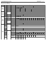
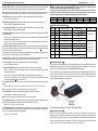
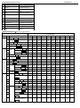
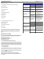
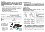
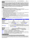
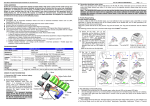
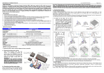
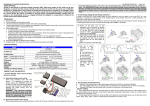
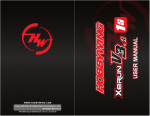
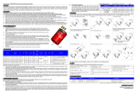
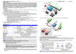
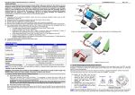
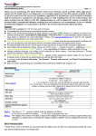
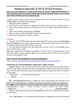
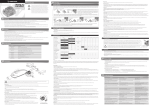
User Manual of XERUN-120A V3.1 Brushless Speed Controller HW-SM510ENG-20121129 【DECLARATION】 Thanks for purchasing our Electronic Speed Controller (ESC). High powered systems for RC models can be very dangerous, so please read this manual carefully. Given that we have no control over the correct use, installation, application, or maintenance of our products, no liability shall be assumed nor accepted for any damages, losses or costs resulting from the use of the product. Any claims arising from the operating, failure or malfunctioning etc. will be denied. We assume no liability for personal injury and/or consequential damages resulting from our product or our workmanship. As far as is legally permitted, the obligation to compensation is limited to the invoice amount of the affected product. 【FEATURES】 ► All in One. Up to ten profiles can be stored in the memory and imported or exported easily. Factory pre-set profiles include Blinky mode, Modify Mode, Stock mode, Practice mode, Offroad mode, Drift mode, Crawler mode. ► Improved Built-in Electronic Switch has stronger current endurance, longer life and higher reliability. ► Aluminum bottom case improves the heat dissipation. ► Improved Aluminum heat-sink. The 1mm gap between the cooling fan and the fins of heat-sink allows more air flow to reduce the temperature of speedo. ► Improved dust-proof design. Rubber rings are applied at the sensor port and the program port. ► External Programming Port (EPP), easy to connect and also a power port for additional fan. ► Advanced Dynamic Timing technology, providing more customization possibilities for highest level competitions. ► Precise throttle and brake control, setting of drag brake and brake strength with more options, new punch and brake rate control functions, and throttle and brake curves through the PC client. ► Integrated Data logger, recording the maximum temperature of ESC and motor as well as the maximum RPM, using LCD Programming box to check easily in the pits. ► Multi Protection Functions, making your running safe with ESC and Motor overheat protection, low voltage cutoff and throttle signal loss protection. ► New USB LINK Software graphic interface, providing extra parameters for advanced settings. ► Portable LCD Programming box, easy to set the ESC and upgrade the firmware by connecting PC. 【SPECIFICATIONS】 Model Cont./ Burst Current/ Resistance Motor Type Supported Cars Applicable 7.2-7.4V Motor Llimit * 9.6-11.1V Voltage Input: BEC Dimension (incl. FAN) Weight (excl. wires) FAN External Programming Port Output * For 540 motors with standard timing. 【FIRST USE OF A NEW ESC】 1. Connect the ESC, motor, receiver, battery and servo correctly, as in the figure. Never plug in the power wire of ESC to the wrong polarity of battery, it will seriously damage the ESC. a) Sensored brushless motor wiring When using brushless motor with Hall Sensor,it is necessary to connect the sensor cable to the “SENSOR” socket on the ESC. The ESC can automatically identify the motor type (sensored or sensorless) by detecting the signal coming from the SENSOR socket. XERUN-120A-SD V3.1 120A / 760A / 0.0003 ohm Sensored and Sensorless Brushless Motors All level competitions: 1/10,1/12 Onroad & Offroad cars ; 1/8,1/10 rock crawlers ≥3.5T(1/10 Touring), ≥5.5T(1/10 Buggy) ≥5.5T(1/10 Touring ), ≥8.5T(1/10 Buggy ) 4.8-11.1V 6V@3A 37.5mm x 31mm x 29.5mm 47g [email protected] ,MAX. 8.4V Direct voltage from battery without DC/DC regulating Page 1 of 6 WARNING! For sensored brushless motor, the #A, #B, #C wires of the ESC MUST be connected with the motor wire #A, #B, #C respectively. Do not change the wires sequence! b) Sensorless brushless motor wiring When using brushless motor without Hall Sensor, the #A, #B, #C wires of the ESC can be connected with the motor wires freely (without any order). If the motor runs in the opposite direction, please swap any two wire connections. Note: For SENSORLESS motor, you can also set the throttle channel of your transmitter to the REVERSE direction, and then the motor will run oppositely. You will need to calibrate the throttle range again after changing the direction of throttle channel. Please keep in mind that this method is ONLY available for SENSORLESS motor. 2. Throttle Range Setting (Throttle Range Calibration) In order to match the ESC to your transmitters throttle range, you must calibrate it before use. Calibration must be performed after any of the following, otherwise the ESC will not work properly; ► Before the first run of a new ESC. ► Before using a new transmitter. ► Following changes to the transmitter settings such as the neutral position of the throttle stick, ATV or EPA parameters, etc. ► Following changes to different ESC software versions. There are 3 points need to be set. They are the “Top point of forward”, the “Top point of backward” and the “Neutral point”. The following figures show how to set the throttle range with a FutabaTM transmitter. A) Switch off the ESC, turn on the transmitter, set the direction of throttle channel to ”REV”, set the throttle trim to “0”, set the “EPA/ATV” value of throttle and brake channels to “100%”, and disable any ABS function on your transmitter. B) Hold the switch button for 2 seconds until the red LED begins to flash. Release the switch button (Refer to the picture on the left side) C) Set the 3 points as follow. With the transmitter at neutral point, press the switch once. The green LED flashes once and the motor sounds "Beep" once. Next, move the transmitter to the full throttle point and press the switch once. The green LED flashes twice and the motor sounds "BeepBeep" once. Then, move the transmitter to the full brake point and press the switch once. The green LED flashes 3 times and the motor sounds "BeepBeepBeep" once. Finally, wait for 3 seconds, then the motor can be controlled properly. 3. Switch ON/OFF the ESC and LED Status In Normal Running WARNING: The ESC may be very hot after running with high load. In such cases, if you want to switch off the ESC, please wait for several minutes to let the ESC’s metal case cool down and then press the switch with caution. You can also use the transmitter to switch off the ESC remotely by keeping full brake for 6 seconds. ► After connecting to the battery, press the switch button once to turn on the ESC. The LED will light up red. ► If the throttle stick is in the neutral range, the LED will be solid red or blinking red (if using NO-TIMING software) ► The LED will blink green when you start to apply throttle or brake, and will turn solid when full throttle or full brake is reached. ► To switch off the ESC, press the switch button once whilst the esc is on. In the situation the motor is still running when the switch is pressed, the ESC will not be turned off. This is to prevent the unexpected shutdown by accident in a race. User Manual of XERUN-120A V3.1 Brushless Speed Controller HW-SM510ENG-20121129 Page 2 of 6 【PROGRAMMABLE ITEMS LIST】 (The italics texts in the form are the default settings) Section General Setting Throttle Control Brake Control Item 1A 1B 1C 1D 1E 2A 2B 2C 2D 2E 3A 3B 3C 3D 3E 3F 3G 4A 4B 4C Timing 4D 4E 5A 5B 5C 5D Programmable Sub-Item Options FORWARD/BRAKE Running Mode Reverse Speed 25% 50% 75% FORWARD/BRAKE/REVERSE FORWARD/REVERSE 100% Voltage Cutoff None Auto ESC Overheat Protection 85℃ 105℃ 125℃ Disable Motor Overheat Protection 85℃ 105℃ 125℃ Disable Punch Rate Switch Point Punch Rate Control 1-30 2nd Stage Punch Rate 1-30 Linear Throttle Neutral Range 4% Brake Strength 6% 8% 0% 12.5% 25% =Drag Brake Initial Brake Brake Rate Switch Point 37.5% 50% 62.5% 75% 0% 20% 30% 40% 1-20 2nd Stage Brake Rate 1-20 Linear Boost Timing 0-64 1000-35000(step 500) Boost End RPM 3000-60000(step 500) Linear Custom (PC Client setting only) Boost Controlled by Throttle Yes Turbo Timing No 0-64 Full Throttle Turbo Activation Method Full Throttle Delay Turbo Turbo Start RPM 100% Custom (PC Client setting only) Boost Start RPM Boost Slope 87.5% 1-99% 1st Stage Brake Rate Brake Input Curve Boost Custom (PC Client setting only) 0-100% Drag Brake Brake Rate Control 1-99% 1st Stage Punch Rate Throttle Input Curve 3.0-11.1V (step 0.1V) Instant 0.05 RPM Full Throttle and RPM 0.1 0.15 0.2 0.25 0.3 0.35 0.4 0.45 0.5 21 24 27 30 Instant 8000-50000 (step 1000) 5E Turbo Engage slope (deg/0.1sec) 3 6 9 12 15 18 5F Turbo Disengage slope (deg/0.1sec) 6 12 18 24 30 Instant 0.6 0.7 0.8 0.9 1.0 User Manual of XERUN-120A V3.1 Brushless Speed Controller 【EXPLANATION FOR EACH PROGRAMABLE ITEM】 Within the ESC software, there are four basic sections for programmable options. Section 1 – General Settings Section 2 – Throttle Settings Section 3 – Brake Settings Section 4 – Timing Settings 【SECTION 1 – GENERAL SETTINGS】 These settings define the basic operating parameters for the ESC 1A - Running Mode: There are three options available for setting of the running mode; Option 1: “Forward Only with Brake” - The car will only go forward and have brakes, but reverse is disabled. This mode is suitable for competition purposes. Option 2: “Forward/Reverse with Brake” – This mode provides a reverse function, which is suitable for practice. Note: The reverse function is engaged by a Double click method. On the first application of backwards throttle, brakes are applied. On returning to the neutral point, and then applying the backwards throttle for a second time, the reverse function will be engaged. However, if at this time the motor is still moving forward (i.e in a double braking action from high speed), the ESC will not go into reverse. The motor must be at 0 rpm to engage reverse. This is a protection function for the drivetrain of the vehicle. Option 3: “Forward / Reverse” – When moving from the forward zone to the backward zone, the ESC will engage reverse immediately. This mode is intended for rock crawling applications, where instant control is required. 1B – Reverse Speed: This setting alters the speed of the car when in reverse, as a percentage of the forward speed. Options: 25%, 50%, 75%, 100% 1C – Voltage Cutoff: This setting defines the low voltage cutoff for use with LiPo batteries, preventing over discharging. The ESC detects the battery’s voltage at any time, if the voltage is lower than the threshold for 2 seconds, the output power will be reduced 70%, after 10 seconds the output power will be completely shut off and the red LED flashes in such a way: “☆-☆-, ☆-☆-, ☆-☆-”. There are three main options for the cutoff setting. Option 1: “None” – No voltage cutoff is used. Select for use with NiCd or NiMH battery types. Option 2: “Auto” – The ESC detects the number of cells present in the battery pack used, and selects a suitable cut-off voltage. Option 3: “User Selected” – The level of the voltage cutoff is defined by the user. The setting selected is for the overall battery voltage. The cutoff can be set from 3.0v – 11.1v, with steps of 0.1v 1D – ESC Overheat Protection: If this function is selected, the output power will be cut-off if the internal temperature of the ESC hits the set level for 5 seconds. When the protection activates, the green LED will flash in the following sequence “☆-, ☆-, ☆-” (Single flash). Options: 85°C, 105°C, 125°C, Disabled 1E – Motor Overheat Protection: If this function is selected, the output power will be cut-off if the internal temperature of the Motor hits the set level for 5 seconds. When the protection activates, the LED will flash in the following sequence “☆-☆-, ☆-☆-, ☆-☆-” (Double flash). Options: 85°C, 105°C, 125°C, Disabled Note: The motor overheat function is only available for sensored brushless motors made by HOBBYWING. For other manufacturers’ motors, this function may not be available, or the sensor may not match the ESC design. For such a case, please disable this function. 【SECTION 2 – THROTTLE CONTROL】 These settings control the action of the forward throttle for the ESC. 2A, 2B & 2C – Punch Rate Control: This group of settings is used to define the starting mode of the ESC. There are a number of the sub-options for this setting. The software has the option to include a dual stage punch rate, which is helpful in allowing a different punch setting for different areas of the forward throttle. Note: Please note that if you use a high punch setting, you must use good quality battery packs with powerful discharge ability. Otherwise these modes cannot get the burst start effect as you want. If the motor cannot run smoothly (the motor is trembling), it may caused by a weak discharge ability of the battery pack. 2A – Punch Rate Switch Point: This setting defines the point in the forward throttle position at which the punch rate HW-SM510ENG-20121129 Page 3 of 6 changes. Options: 1-99%, in steps of 1%. 2B – 1st Stage Punch Rate: This is the level of punch used in the first stage of the punch range, before the switch point. Setting 1 is least punch, with 30 being the most. Options: 1 – 30, with steps of 1. 2C – 2nd Stage Punch Rate: This is the level of punch used in the second stage of the punch range, after the switch point. Setting 1 is least punch, with 30 being the most. Options: 1 – 30, with steps of 1. 2D – Throttle Input Curve: This setting is used to define the input throttle curve into the ESC. Option 1: “Linear” – This is where the forward throttle position of the transmitter directly relates to the forward throttle position into the ESC. Option 2: “Custom” – This allows for a multi-step setting to the forward throttle. This differs from exponential on the transmitter, in that the forward throttle input into the ESC can be defined in multiple increasing steps. 2E – Throttle Neutral Range: This setting is used to define the width of throttle neutral range. 【SECTION 3 – BRAKE CONTROL】 These settings control the action of the backward throttle for the ESC. 3A – Drag Brake: This setting sets the amount of drag brake applied at neutral throttle to simulate a slight braking effect. The level can be set as a percentage of the overall backward throttle. Options: 0-100%, with steps of 1% 3B – Brake Strength: This settings defines the overall brake level as a percentage of the backward throttle. A higher value will result in stronger brakes. Options: 0%, 12.5%, 25%, 37.5%, 50%, 62.5%, 75%, 87.5%, 100% 3C – Initial Brake: This setting refers to the level of braking applied in the initial portion of the backward throttle. The default value is equal to the drag brake force, so the brake effect can be very smoothly. Options: “=Drag Brake”, 0%, 20%, 30%, 40% 3D, 3E & 3F – Brake Rate Control: This setting is used to define the braking mode of the ESC. There are a number of the sub-options for this setting. The software has the option to include a dual stage braking rate, which is helpful in allowing a different brake setting for different areas of the throttle. Note: This setting can be considered similar to the forward throttle Punch Rate Control, but acting on the backward throttle. 3D – Brake Rate Switch Point: This setting defines the point in the backward throttle position at which the brake rate changes. Options: 1-99%, in steps of 1%. 3E – 1st Stage Brake Rate: This is the level of brake rate used in the first stage of the range, before the switch point. Setting 1 is least braking rate, with 30 being the most. Options: 1 – 20, with steps of 1. 3F – 2nd Stage Brake Rate: This is the level of brake rate used in the second stage of the range, after the switch point. Setting 1 is least braking rate, with 30 being the most. Options: 1 – 20, with steps of 1. 3G – Brake Input Curve: This setting is used to define the input brake curve into the ESC. Option 1: “Linear” – This is where the backward position of the transmitter directly relates to the backward throttle position into the ESC. Option 2: “Custom” – This allows for a multi-step setting to the throttle. This differs from exponential on the transmitter, in that the backward throttle input into the ESC can be defined in multiple increasing steps. 【SECTION 4 – TIMING SETTINGS】 These settings define the dynamic timing settings for the ESC. Note: Maximum total timing points that can be added is 64. If the total timing for both Boost and Turbo exceeds 64 points, then only 64 will be applied. Generally, Boost will be applied first, then Turbo, although this is dependent on the Boost User Manual of XERUN-120A V3.1 Brushless Speed Controller and Turbo settings. We use “point” here instead of “degree” is to clarify the number is not a real degree. 4A, 4B, 4C, 4D, 4E – Boost – The boost setting group defines the parameters for the boost timing settings. Within the boost RPM range, the boost will change dynamically in relation to the Motor RPM, Boost timing and Boost Slope. Note: Boost timing is effective through the whole throttle range. If the ESC meets the RPM requirements, the boost will be added regardless of throttle position. The only exception is if item 4E – Boost Controlled by Throttle is activated. 4A – Boost Timing: This setting sets the total amount of boost timing added across the boost RPM range. Options: 0 - 64 points, with steps of 1 4B – Boost Timing Start RPM: This setting defines the RPM at which the boost timing is started to be added. Options: 1,000rpm – 35,000rpm, with steps of 500rpm. 4C – Boost Timing End RPM: This setting defines the RPM at which the full level of boost timing is applied. HW-SM510ENG-20121129 Page 4 of 6 【SUGGESTED BOOST AND TURBO TIMING SETTINGS】 WARNING: The following settings are recommendation for 1/10 scale on-road touring cars, and the motor has an initial mechanical timing (also called: Endbell timing) of 0 to 5 Degree. Incorrect Boost and Turbo timing settings will cause ESC or motor burning. Check your motor’s instruction for proper gear ratio and start from the suggest timing range as follow. Always remember to monitor your motor and ESC’s temperature after one or two minutes’s running when using a new faster setting. Motor (Turns) Boost Timing Turbo Timing 3.5T-4.0T 0 5 4.5T-5.5T 0 10 6.5T-7.5T 5 10 8.5T-9.5T 10 15 10.5T-11.5T 20 25 13.5T-21.5T 30 25 【SUGGESTED POWER CONFIGURATION】 Motor 数 3.5T 9100KV 9.0-11.0 4.5T 7300KV 8.4-10.0 Option 1: “Linear” – This applies the boost in a linear manner within the RPM Range. The ESC calculates the rate of boost addition off of Setting 4A, 4B & 4C. 5.5T 6000KV 8.0-9.4 9.5-11.0 6.5T 5200KV 7.4-8.4 9.0-11.0 Option 2: “Custom” – This allows for a non-linear addition of Boost timing within the RPM range. The boost can be applied in multiple increasing steps throughout the range. 8.5T 4000KV 6.0-7.0 8.0-9.6 10.5T 3300KV 5.0-6.0 7.0-8.5 XERUN-120A-V3.1 11.5T 3000KV 4.5-5.5 6.5-8.0 XERUN-120A-V3 13.5T 2500KV 4.0-5.0 6.5-7.5 XERUN-120A-V2.1 17.5T 1900KV 3.8-4.5 5.5-7.0 XERUN-90A-V2.1 21.5T 1600KV Options: 3,000rpm – 60,000rpm, with steps of 500rpm. 4D – Boost Slope (BT Slope): This setting controls how the boost timing is applied within the RPM range. There are two options for this setting. 4E – Boost Controlled by Throttle: This setting is a limit for the boost timing addition, in relation to the throttle position, which can aid car stability whilst on throttle. If enabled, the ESC will monitor the throttle position and Motor RPM, and limit the maximum amount of available boost timing. E.g. If the boost timing is set to 36 points and the boost end RPM setting has been achieved, but the throttle position is only 50%, then only 32 points (50% of 64 points) of boost will be applied. 5A, 5B, 5C, 5D, 5E, 5F – Turbo – The turbo setting group defines the parameters for the turbo timing settings. Turbo timing is additional timing added at higher speed, and is effective for extra speed on long straights. 5A – Turbo Timing(TT: This setting sets the total amount of turbo timing that can be applied. Options: 0 - 64 points, with steps of 1 5B – Turbo Activation Method: This defines the activation method for the addition of the turbo timing. Option 1: “Full Throttle” – Turbo timing is activated only after 100% throttle has been applied, and the full throttle delay (Setting 5C) is elapsed. Option 2: “RPM” – Turbo timing is activated only after the Turbo Start RPM (setting 5D) is achieved. Option 3: “Full Throttle and RPM” – This is a combination of option 1 and option 2, where the turbo timing will only active if both the full throttle and RPM conditions are met. KV FDR (1/10 Touring )* FDR (1/10 Buggy)* ESC XERUN-120A-V3.1 *Use 2S LiPO or 7.2V NiMH battery and Zero Timing mode. 【PROGRAM BOX CONNECTION】 This ESC needs an LCD PROGRAM BOX to set the programmable items directly or through HOBBYWING USB LINK software which is installed on your PC. The firmware version of the box requires V3 compatible levels. If it is in an earlier version, you need to upgrade the firmware through the HOBBYWING USB LINK software. Use the setting cable included in the ESC package to connect the ESC to the LCD PROGRAM BOX (see figure below). Connect the ESC to the batter pack and switch on the ESC and you can set the programmable items except the “Custom” Options of several items. You can also load the factory pre-set profiles for an easy start. (Refer to the instruction of LCD PROGRAM BOX for detail operation.) 5C – Full Throttle Turbo Delay: This setting is used to set the delay after achieving full throttle that the Turbo timing is applied. Options: “Instant”, 0.05s, 0.1s, 0.15s, 0.2s, 0.25s, 0.3s, 0.35s, 0.4s, 0.45s, 0.5s, 0.6s, 0.7s, 0.8s, 0.9s,1.0s Note: If Setting 5B is set to Option 2, this setting will have no effect on the turbo activation. 5D – Turbo Start RPM: This setting is used to define the RPM value at which turbo is activated. Options: 8,000rpm – 50,000rpm, with steps of 1,000rpm. Note: If item 5B is set to Option 1, this setting will have no effect on the turbo activation. 5E – Turbo Engage Slope: This setting relates to the rate of engagement when the activation conditions are met. The rate is defined in points added per 0.1s. A higher value means faster addition of Turbo timing. Options: 3, 6, 9, 12, 15, 18, 21, 24, 27, 30, “Instant” 5F – Turbo Disengage Slope: This setting relates to the disengagement of the turbo timing, which can help to avoid a large breaking effect when coming off the throttle with high turbo levels. The rate of disengagement is defined as points per 0.1s, with a higher value meaning a faster disengagement. Options: 6, 12, 18, 24, 30, “Instant” 【FACTORY PRE-SET PROFILES】 The ESC has 10 factory pre-set profiles in the memory. You can choose one profile which is most likely to your application if you are not familiar with the settings. Choose a proper gear ratio according to your motors and track conditions, then you may start your running. You can also change the pre-set values in the profile for better performance and save it as your own profile with a new profile name. For example, you can change the pre-set profile name “Modify Racing” to “TITC2013 _4.5” which contains the settings of 4.5T motor in TITC2013 event. User Manual of XERUN-120A V3.1 Brushless Speed Controller No. HW-SM510ENG-20121129 Profile Name Application 1 Modify Racing For modify class of touring car racing 2 Zero Timing For zero timing (blinky mode) class of touring car racing 3 Practice For daily practice or fun , with reverse 4 Sport Racing For sport class of touring car racing, with less Turbo timing. 5 Stock-10.5T For stock class(10.5t motor) touring car racing 6 Stock-13.5T Racing For stock class(13.5t motor) touring car racing 7 Stock-17.5T Racing For stock class(17.5t motor) touring car racing 8 Buggy or Short course For 1/10 buggy or short course racing 9 Rock Crawler For rock crawler 10 Drift Car For drift car 【PRE-SET PROFILE DEFAULT VALUE】(Default Value may be changed in different firmware) Pre-set Profile Default Value Section Item General Setting 1A Running Mode 1B Reverse Speed 1C Voltage Cutoff 1D ESC Overheat Protection 1E Motor Overheat Protection Throttle Control 2A 2B Programmable Items Running Mode Reverse Speed Voltage Cutoff ESC Overheat Motor Overheat Punch Rate Switch Point PunchRate 1st Stage Punch Rate Control PR SW Point 1st Punch Rate 2nd Stage Punch Rate Zero Timing Practice Sport Stock--10.5T Stock--13.5T Stock--17.5T Buggy&SCT Crawler Drift For/Brake For/Brake For/Rev/Brake For/Brake For/Brake For/Brake For/Brake For/Brake For/Rev For/Brake 25% 25% 25% 25% 25% 25% 25% 25% 100% 25% Auto Auto Auto Auto Auto Auto Auto Auto Auto Auto 105 ℃ 105 ℃ 105 ℃ 105 ℃ 105 ℃ 105 ℃ 105 ℃ 105 ℃ 105 ℃ 105 ℃ 105 ℃ 105 ℃ 105 ℃ 105 ℃ 105 ℃ 105 ℃ 105 ℃ 105 ℃ 105 ℃ 105 ℃ 50% 50% 50% 50% 50% 50% 50% 40% 50% 50% 20 20 30 30 10 20 20 30 30 30 20 20 20 15 30 30 Brake Control 15 30 20 20 linear 6% linear 6% linear 6% linear 6% linear 6% linear 6% linear 6% linear 6% linear 6% linear 6% 10% 5% 5% 5% 5% 0% 0% 0% 100% 0% 75% =drag brake 100% =drag brake 100% =drag brake 100% =drag brake 75% =drag brake 62.5% =drag brake 62.5% =drag brake 75% =drag brake 100% =drag brake 50% =drag brake 50% 50% 50% 50% 50% 50% 50% 50% 50% 50% 20 10 20 20 20 20 20 10 20 10 20 10 10 10 10 10 10 10 20 10 linear linear linear linear linear linear linear linear linear linear 0 Deg 0 Deg 0 Deg 0 Deg 20 Deg 30 Deg 36 Deg 0 Deg 0 Deg 0 Deg 15000 6000 6000 6000 6000 4000 2000 6000 6000 6000 Boost End RPM BT End RPM 25000 22500 22500 22500 18000 15000 12000 22500 22500 22500 4D Boost Slope BT Slope Linear Linear Linear Linear Linear Linear Linear Linear Linear Linear 4E Boost Controlled by Throttle BT By TH Yes Yes Yes Yes Yes No No Yes Yes Yes 5A Turbo Timing 10 Deg 5B Turbo Activation Method Full TH 0 Deg Full TH 10 Deg Full TH 10 Deg Full TH 25 Deg Full TH 25 Deg Full TH 28 Deg Full TH 10 Deg Full TH 0 Deg Full TH 0 Deg Full TH 5C Full Throttle Delay (sec.) Full TH Delay 0.3 0.3 0.3 S 0.3 0.3 0.2 0.2 Instant 0.3 0.3 5D Turbo Start RPM 20000 20000 20000 20000 20000 20000 20000 20000 20000 20000 15 12 12 12 18 24 24 9 12 12 24 24 24 24 18 18 18 24 24 24 2C 2D Throttle Input Curve 2E Throttle Neutral Range 3A Drag Brake 3B Brake Strength 3C Initial Brake Initial Brake Brake Rate Control Brake Strength Brake Input Curve Timing 5F BR SW Point 1st Brake Rate 2nd Brake Rate Brake Curve Boost Timing Boost Timing Boost Start RPM 4B 5E 1st Stage Brake Rate 2nd Stage Brake Rate 4A 4C Neutral Range Brake Rate Switch Point 3F 3G TH Curve Drag Brake 3D 3E 2nd Punch Rate Modify BT Start RPM Boost Turbo Turbo Timing TT Activation TT Start RPM Turbo Engage slope (deg/0.1sec) TT Eng Slope Turbo Disengage slope TT DEng Slope (deg/0.1sec) Page 5 of 6 User Manual of XERUN-120A V3.1 Brushless Speed Controller 【BASIC SETTING RULES FOR STOCK RACING】 1. To get faster top speed, you need: A. More Timing, Boost timing for both bottom end and top end while Turbo timing for long straight. B. Lower FDR (larger pinion) C. Higher discharge rate battery pack HW-SM510ENG-20121129 Page 6 of 6 【TROUBLE SHOOTING】 Symptom Possible Reasons Input wiring problem ESC can't be switched on. LED on the Battery defective switch does not light on, FAN doesn't work ESC switch defective Solution Check wires and connectors of the input Replace with battery pack in good condition Send in product for repair Motor doesn't work, ESC sounds “beepbeep” alert tone every 1 second Input voltage is not in the proper working range Check the voltage of the battery pack Motor doesn't work,the red LED solid on ESC signal cable plugged in incorrectly Plug ESC signal cable to receiver CH2 (TH) channel correctly The wire connections between the ESC and the motor need to be changed Swap any two wire connections between the ESC and the motor. (Note: This method is ONLY available for SENSORLESS motor ) car with reversed gearbox Can not use a sensored brushless system, change to sensorless mode if you want The ESC has entered the “Low voltage protection mode” or the “ Over-heat protection mode” If red LED flashes,low voltage of battery detected,stop running and change battery pack If green LED flashes,Motor or ESC Over-heat detected, stop running and change to a correct setting of Timing, Gear Ratio etc. A. Higher FDR in the reasonable range Radio Inteference Change location of receiver and ESC B. Less Boost and Turbo timing Low battery discharge rate Change to high rate packs Motor or sensor problem Change motor or sensor board Wrong gear raito Adjust gear ratio 2. To get faster acceleration, you need: A. More Boost timing B. Lower Boost Start RPM and Boost End RPM C. Higher FDR (smaller pinion) Motor runs backwards when accelerating forward on radio D. Less Turbo Delay E. Higher Turbo Slope Rate F. Higher Punch Rate The motor stops running while in working state 3. To have lower motor temperature and more running time, you need: Motor stuttering under heavy acceleration C. Higher Boost Start RPM and Boost End RPM D. More Turbo Delay E. Lower Turbo Slope Rate Do not change too much at one time, make one change only and monitor the temperature. After you have good speed with normal motor temperature, save your settings for future reference. 【RUNNING DATA INFORMATION LOG FUNCTION】 The Xerun V3 Electronic Speed Controller (ESC) has been designed to implement a built-in integrated data information logger, its main function is to record and store the following running data for the Xerun V3 brushless system: Maximum temperature data information of the ESC Maximum temperature data information of the sensored motor Minimum voltage data information of the battery Maximum RPM data information of the motor. 1. To save the running data information please follow the instructions below After you have completed your initial run, when the ESC is switched to the off position by pressing the built-in LED On/Off button or by activating full brakes on your transmitter for a period of 6 seconds, the running data information that has been collected by the built-in data logger will be automatically stored in the ESC’s memory. Be aware that if you switch off the ESC by disconnecting the battery, the running data information that has been recorded will be deleted with no option of recovering the lost data. 2. To read the logged data information Connect the LCD program box to the ESC; turn on the ESC to allow it to communicate with the LCD program box. At any programmable value setting user interface which is displayed, press 【R/P】button to return to the current mode. By continuing to press the【R/P】button on the LCD program box it will allow you to view the following 4 options in which the data has been recorded and saved in the following sequence. Current Mode ESC Temperature Motor Temperature Minimum Voltage Maximum RPM Besides the LCD program box, the USB Link Software can also be used to read the logged data information via your personal computer (PC) Red and green LED flashing when transmitter in neutral point ESC detects abnormal signal from the sensor and changes to sensorless mode automatically Connctions from ESC to motor are Motor trembles and can not start smoothly wrong. ESC defective Check sensor cable connection or replace a new one Hall sensors in the motor are damaged, change the motor Check the connections,make sure A-A,B-B,C-C Send in product for repair