1
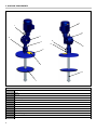
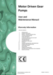
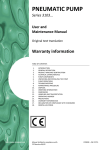
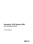
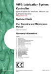
CANNONPUMP Electric barrel pump User Operating and Maintenance Manual Original text translation Warranty Information CONTENT 1. 2. 3. 4. 5. 6. 7. 8. 9. 10. 11. 12. 13. 14. 15. 16. 17. 18. INTRODUCTION GENERAL DESCRIPTION IDENTIFICATION OF THE MACHINE TECHNICAL FEATURES MACHINE COMPONENTS UNPACKING AND INSTALLATION INSTRUCTIONS FOR USE PROBLEMS AND SOLUTIONS MAINTENANCE PROCEDURES DISPOSAL ORDER INFORMATION DIMENSIONS HANDLING AND TRANSPORT PRECAUTIONS FOR USE OPERATIONAL HAZARDS WARRANTY DECLARATION OF COMPLIANCE DISTRIBUTORS Manual compiled in accordance with Directive CE 06/42 http://www.dropsa.com C2124IE– WK 17/11 1. INTRODUCTION This is the operating and user manual for the Dropsa CannonPump. It is possible to obtain the latest documentation by visiting our website, www.dropsa.com This manual contains important operating and safety information for users of this product. It is essential that you carefully read this manual and conserve a copy with the product so that other users may consult it at any time. 2. GENERAL DESCRIPTION CannonPump is an electrically driven piston barrel pump. It is ideally suited for operation in environments where there is no compressed air available and therefore traditional pneumatic barrel pumps cannot be used. Another key characteristic of the piston pumping mechanism design allows to it so handle hard greases without the need to preprime the pump with oil. The pump also has a return line connection that allows grease pressure to be vented directly to the barrel and this means that it can be used in dual line systems without any additional modification to add a return line on the follower plate. Dual Line Systems Lubrication systems engineered with the Dual Line system are generally used on large scale machinery and in harsh operating conditions to lubricate multiple points on large machines. The system can grow to a very complex one with a length that often can exceed 60 meters. The large section of pump packages together with many custom design optionsdallowsoanyolubricationosystemotoobeodevelopedoreliablyeandecost-effectively. DropsA skilled engineers are available to design large scale project and provide installation, commissioning, support and training anywhere in the world. These pumps are supplied without accessories. It is the responsibility of the installer to ensure that the pump is suitable protected with any necessary electrical or mechanical accessory (e.g. Fuses, emergency stop switches etc). The follower plate: It is necessary to use a follower plate to correctly pump heavy grease (e.g. NLGI 2)). The plate is manufacturered in 10mm/0.39” thick steel and has a lip seal around the edge and and an O Seal along the central shaft to avoid grease leak-through. The follower plate: - Compresses grease thereby avoiding air pockets; - Allows effective emptying of the barrel by wiping grease from the side of the barrel that would otherwise go to waste. The Barrel Cover reduces the possible contamination of the grease in the barrel. It is supplied with retaining screws and also has the purpose of holding the pump in a correct vertical configuration. 2 3. IDENTIFICATION OF THE MACHINE On the pump cover there is a product identification label that indicates the part number and characteristic of the pump, including motor voltage. Always ensure you have the correct product for your application. 4. TECHNICAL FEATURES 4.1 ENVIRONMENTAL CONDITIONS grease NLGI 0 Working temperature -10 °C -14 °F ) grease NLGI 1 grease NLGI 2 +5 °C 4.2 FEATURES NB The following benefits are related to the use of temperature + 20 ° C (+ 68 ° F) GENERAL FEATURES 230V/400Vac - 3Ph - 50Hz – 0.55 kW 240/415Vac – 3Ph – 50Hz – 0.55 kW 280/480Vac - 3Ph - 60Hz – 0.65 kW Supply voltage 110Vac -1Ph - 60Hz – 0.9 kW 230 -1Ph - 50Hz – 0.55 kW 24Vcc – 0.55 kW Pump type Piston mechanism Outlet connection G 3/8“ Maximum pressure 250 bar (three phases motor) – 200 ( mono phase motor) Drum capacity 20 kg/25Kg - 50Kg – 180 Kg/200 Kg Lubricant Grease NLGI 2 max Flow 125 cm3/min Degree of protection IP55 Gear reducer Screw and helical wheel R=50/1 Drum Fixture Includes radially located retaining screws Pressure By-pass Integrated adjustable 80÷250 bar Minimum level Optional Return Line for Dual Line systems Port 1/4" BSP 3 5. MACHINE COMPONENTS 8 1 12 3 2 9 4 11 10 5 6 13 7 PUMP COMPONENTS 4 1 Lifting Lug 2 Outlet 3 Oil lamp 4 Oil drain plug 5 Drum cover 6 Identification Label 7 Follower plate 8 Motor 9 By-pass 10 Oil Fill plug 11 Return Line (plugged) 12 Gearbox reducer 13 Pump Shaft 6. UNPACKING AND INSTALLATION 6.1 UNPACKING Once a suitable installation position has been identified, unpack the pump and prepare for installation. It is important to inspect the pump to ensure that there has been no damage during transportation. The packaging material used does not require any special disposal procedures. You should refer to you regional requirements. 6.2 INSTALLATION Allow sufficient space for the installation, leaving minimum 100 mm (3.93 in.) around the pump. Place the pump at shoulder height to avoid an unnatural posture or possibility of sustaining impacts. CannonPumps must be installed vertically inserting the shank into the grease barrel until it reaches the bottom of the drum, using the lifting lug. If you purchase separately the pump and the follower plate with lid, remove the ring on the pump shaft, put the lid and follower plate in the correct direction (the lip of the seal to the up) and finally put the ring in the initial position . WARNING: When using a grease follower plate, it is recommended to check for crushes on drum sides which could prevent the follower plate from descending into the barrel. Use only intact drums with no defects. 6.3 ELECTRICAL CONNECTIONS Damage to the power cable and terminal box could imply contact with parts power components and associated dangers of electricution. Care must be taken when making electrical connection. Check the integrity of the terminal box and the pump in general. In case of any damage, do not put the unit in operation If the power cable has been damaged, replace it immediately. Dismantling of the unit must be done by qualified maintenance personnel with electrical and mechanical skills.. In order to prevent possibility of electricution due to earthing of live wires a differential trip should be fitted to the power supply to protect the user. Use a Trip device that activates at a differential level of 0,03 Ampere and a maximum of 1 second. Switching Isolation must equal 10 kA with a nominal current of 4 A The pump should never be used in hazardous enviornments or immersed in any fluids. Always use safety gloves and glasses when handling lubricants. Do not use lubricants that may contains substances incompatible with NBR Rubber. Follow all health and safety rules required by law. Attention: all electrical component must be earthed. This also includes all sensors. The earth cable should always be approximately 100mm longer than the signal wires and guarantee that if they become undone the earth cable is always the last one to disconnect Check list before startup: Check integrity of the pump; Check Voltage and power supply is correct; Check lubricant is compatible; Ensure correct operating environment (temperature/humidity) Double Check all electrical connections. 5 7. INSTRUCTIONS FOR USE 1. 2. 3. 4. Switch on the pump by pressing the start button on the control system in use; Check that the pump is running; Adjust the pressure by pass to the desired setting; Verify that lubricant is correctly dispensed the lubrication system is functioning correctly. 8. PROBLEMS AND SOLUTIONS WARNING: The machine can be opened and repaired only by Dropsa authorized staff. The following is a diagnostic table showing possible problems, causes and solutions. Having consulted the following table, if problems still exist you should contact a specialized Dropsa technical support point for assistance in resolving any remaining problems. N° 01 PROBLEM The electric motor of the pump is not working The electric motor is working, but the pump does not deliver lubricant 02 The pump is working but no grease arrives at the lubrication point. 03 The pump starts briefly but then stops. 04 POSSIBLE CAUSE SOLUTIONS No power at the motor Check the power supply system and the fuse. Air trapped in the outlet or in the lubricant pumping chamber. Disconnect the outlet tubing and cycle the pump until clean grease with no air bubbles is pumped from the outlet. Reconnect as appropriate. Broken Piping or leaking fitting. Check the distribution system to ensure that no leaks are present and that the distribution system is functioning correctly. Defective or overheated Motor. Allow the motor to cool for a few minutes and then try again. If the problem persists the pump may need a service by a Dropsa technician. CAUTION: Make sure the power supply, hydraulics are disconnected before performing any maintenance. 6 9. MAINTENANCE PROCEDURES The pumps require only minimal maintenance. To facilitate maintenance it is suggested to install the pump in an easily accessible location (see paragraph 6.2). Periodically check piping joints to detect possible leaks. Periodically check that there is sufficient oil in the gearbox. If necessary top up with ISO VG100 (DIN-51524-2) mineral gear oil. Keep the machine unit clear to readily detect possible leaks. The machine does not require any special tool for checking or maintenance tasks. However, it is recommended the use only of appropriate and in good conditions tooling, protective devices (gloves) and and clothing (in according to current regulations) to avoid hazards to equipment or persons. 10. DISPOSAL The unit does not contain any harmful substances and should be disposed of following local regulations, including any recycling information indicated on the components themselves. Upon demolition of the machine you must destroy the identification label and any other document. 7 11. ORDER INFORMATION 11.1 CANNONPUMP WITHOUT FOLLOWER PLATE AND COVER Part Number Drum Delivery (Kg) 0234525 0234535 0234545 0234526 0234536 0234546 0234527 0234537 0234547 0234528 0234538 0234548 20-25 50 180/200 20-25 50 180/200 20-25 50 180/200 20-25 50 180/200 Power supply 230/400Vac 3Ph – 50Hz – 0.55kW 240/415Vac 3Ph – 50Hz – 0.55kW 280/480Vac 3Ph – 60Hz – 0.65kW 110Vac 1Ph – 60 Hz – 0.9 kW 230Vac 1Ph – 50Hz – 0.55kW 24Vcc – 0.55kW 11.2 CANNONPUMP WITH FOLLOWER PLATE AND COVER Part Number Drum Delivery (Kg) 0234520 0234550 0234530 0234540 0234521 0234551 0234531 0234541 0234522 0234552 0234532 0234542 0234523 0234553 0234533 0234543 20 25 50 180/200 20 25 50 180/200 20 25 50 180/200 20 25 50 180/200 Power supply 230/400Vac 3Ph – 50Hz – 0.55kW 240/415Vac 3Ph – 50Hz – 0.55kW 280/480Vac 3Ph – 60Hz – 0.65kW 110Vac 1Ph – 60 Hz – 0.9 kW 230Vac 1Ph – 50Hz – 0.55kW 24Vcc – 0.55kW 11.2 SPARE PARTS AND ACCESSORIES Pump Accessories and spare parts Item Cover Follower Plate Pump size part number 20 Kg 1141601 25 kg 1141606 50 kg 1141603 180 / 200 kg 1141605 1141600 1141607 1141602 1141604 Other spare parts Part Item Number 0234496 3133456 8 Bypass 200 kg Drum Lift Kit Engines parts Part Power supply Number 230/400V AC 3Ph – 50Hz – 0.55kW 3301536 240/415V AC 3Ph – 50Hz – 0.55kW 280/480V AC 3Ph – 60Hz – 0.65kW 3301543 110V AC 1Ph – 60 Hz – 0.9 kW 3301542 230V AC 1Ph – 50Hz – 0.55kW 3301540 24V DC – 0.55kW 12. DIMENSIONS ~ 612 DRUM DELIVERY (kg) 20-25 50 180/200 A B C 290 365 590 315 400 600 520 720 900 9 13. HANDLING AND TRANSPORT Prior to shipping, the equipment is carefully packed in cardboard package. During transportation and storage, always maintain the pump the right way up as indicated on the box. On receipt check that package has not been damaged. Then, storage the machine in a dry location. Handling of the Pump must be done by at least two people. Lift the packaging taking note of the orientation of the pump. The product can withstand a storage temperature between -20 to + 50 °C; however it is necessary to ensure that the product has stabilized at a minimum temperature of +5 °C before putting it into operation 14. PRECAUTIONS FOR USE It is necessary to read with due care all instructions regarding the use of this product. The operator must know how to correct operate the product and all associated risks of having lubricants under pressure. Therefore it is recommended: Verify chemical compatibility of the lubricant with the pump and the entire lubrication system. Ensure that all lubricant safety data is taken into consideration. Never exceed the maximum operating pressure or any characteristic of the pump. Check the product identification label. Only ever use original spare parts. Whenever a part is replaced anywhere in a lubrication system, ensure that it is rating and operating mode compatible with all other parts of the system. WARNING! Never attempt to stop or divert any leaks with hands or other body parts. Note: It is important that all operators and maintenance personnel follow their local safety information. In particular always use personal protection equipment (gloves, safety glasses and protective clothing as a minimum) when handling this equipment or any lubricant. lubricants can often cause skin irritations and therefore appropriate safety measures must be adopted. WARNING: It’s necessary read carefully the warnings about the risks involving the use of a pump for lubricants. The user must know the operation through the User Manual and Maintenance. Power supply Any type of intervention must not be carried out before the unplugging of the machine from power supply. Make sure that no one can start it up again during the intervention. All the installed electric and electronic equipment, reservoirs and basic components must be grounded. Flammability The lubricant generally used in lubrication systems is not normally flammable. However, it is advised to avoid contact with extremely hot substances or naked flames. Pressure Prior to any intervention, check the absence of residual pressure in any branch of the lubricant circuit as it may cause oil sprays when disassembling components or fittings. After long periods of inactivity required to check all the pressure parts. Do not subject to violent shocks of the fittings, pipes and parts under pressure. A hose connection or a damaged are DANGEROUS, arrange for their replacement. We recommend only the use of original spare parts. 10 Noise During normal operating conditions the pump does not produce excessive noise (less than 70 dB(A) ) at the distance of 1 m (39.3 inches) from the pump. The following is a comparison table between NLGI (National Lubricating Grease Institute) and ASTM (American Society for Testing and Materials) for greases, showing the permissible values for the CannonPump NOTE: The pump has been designed to work with greases with a maximum viscosity of NLGI 2 Always use lubricants that are compatible with NBR Rubber. The lubricant used during final testing of the unit is a NLGI 2 grease. GREASES NLGI 000 00 0 1 2 ASTM 445 – 475 400 – 430 355 – 385 310 – 340 265 –295 For more information on technical and security measures, see the Security tab of the Product (Directive 93/112/EEC) relating to the type of lubricant chosen and supplied by the manufacturer. 15. OPERATIONAL HAZARDS Verification and assessment relative to machine safety have been carried out according to the guidelines set out within the European Machine Directive using a matrix evaluation schematic with the generation of technical file as required by the directive. The lists used are of two types: Risk evaluation (UNI EN ISO 14121-1). Conformity to essential safety requisites (Machine Directive –CE 06/42). The following hazards have been identified as a result and must be considered during operation. During Maintenance oil may be discharged at low pressures (oil squirt). To counter this, maintenance must be carried wearing appropriate personal protective clothing and glasses. Electricution: This can occur if the user does not securely connected the wires inside the terminal box. Electrical connections must therefore be carried out only by a competent electrician. Physical Strain due to poor positioning of the unit. Detailed Dimensional information is given in this manual to avoid poor positioning. Use of incorrect lubricant or fluids. Lubricant information is contained in this manual and on the pump itself. FLUIDS NOT ALLOWED FLUIDS Lubricants with abrasive additives Lubricants with silicone lubricant additives Petrol - solvents - flammable liquid Corrosive products Water DANGERS wear of pump internal components Seizure of pumping element Fire - explosion - damage to seals Corrosion of the pump - damage to people Oxidation of the pump Food Contamination 11 16. WARRANTY All products manufactured and marketed by Dropsa are warranted to be free of defects in material or workmanship for a period of at least 12 months from date of delivery. Extended warranty coverage applies as follows. Complete system installation by Dropsa: 24 Months. All other components: 12 months from date of installation; if installed 6 months or more after ship date, warranty shall be maximum of 18 months from ship date. If a fault develops, notify Dropsa giving: A complete description of the alleged malfunction The part number(s) Test record number where available (format xxxxxx-xxxxxx) Date of delivery Date of installation Operating conditions of subject product(s) We will subsequently review this information and supply you with either servicing data or shipping instruction and returned materials authorization (RMA) which will have instructions on how to prepare the product for return. Upon prepaid receipt of subject product to an authorized Dropsa Sales & Service location, we will then either repair or replace such product(s), at out option, and if determined to be a warranted defect, we will perform such necessary product repairs or replace such product(s) at our expense. Dropsa reserves to right to charge an administration fee if the product(s) returned are found to be not defective. This limited warranty does not cover any products, damages or injuries resulting from misuse, neglect, normal expected wear, chemically caused corrosion, improper installation or operation contrary to factory recommendation. Nor does it cover equipment that has been modified, tampered with or altered without authorization. Consumables and perishable products are excluded from this or any other warranty. No other extended liabilities are states or implied and this warranty in no event covers incidental or consequential damages, injuries or costs resulting from any such defective product(s). The use of Dropsa product(s) implies the acceptance of our warranty conditions. Modifications to our standard warranty must be in made in writing and approved by Dropsa. 12 17. DECLARATION OF COMPLIANCE Dropsa Spa Via Benedetto Croce, 1 20090 Vimodrone (MI) Italy Tel.: Fax Sales: E-mail: Web site: (+39) 02. 250.79.1 (+39) 02. 250.79.767 [email protected] http://www.dropsa.com DICHIARAZIONE DI CONFORMITÁ/DECLARATION OF COMPLIANCE WITH STANDARDS/ DECLARATION DE CONFORMITE/ KONFORMITÄTSERKLÄRUNG DES STANDARDS /DECLARACIÓN DE CONFORMIDAD/ DECLARAÇÃO DE CONFORMIDADE La società Dropsa S.p.A., con sede legale in Milano, Via Besana,5/ Dropsa S.p.A., registered office in Milan, Via Besana,5 / Dropsa S.p.A. au Siège Social à Milan, Via Besana,5/ Dropsa S.p.A., Sitz in Milano, Via Besana 5/ La sociedad Dropsa S.p.a., con sede legal en Milán, Via Besana,5/ A Dropsa S.p.A, com sede em Milão, via Besana, nº 5 DICHIARA /CERTIFIES / CERTIFIE/ ZERTIFIZIERT, DASS/ DECLARA/ CERTIFICA: che la macchina denominata/that the machine named / que la machine dénommée/ Die Maschine mit der Bezeichnung/ que la máquina denominada/ que o equipamento denominado "CannonPump" è conforme alle condizioni previste dalle Direttive CEE /has been constructed in conformity with the Directives Of The Council Of The European Community on the standardization of the legislations of member states/ a été construite en conformité avec les Directives Du Conseil Des Communautes Europeennes/ Entsprechend den Richtlinien des Rates Der Europäischen Union, für die Standarisierung der Legislative der Mitgliederstaaten, konstruiert wurde/ cumple con las condiciones establecidas por las directivas comunitarias/ foi construído em conformidade com as diretivas do Conselho das Comunidades Europeias: 2006/42 Direttiva macchine /Machinery Directive / 2006/42 Directive machines / Maschinenrichtlinien/ Maquinaria 2006/42/CEE /Directiva 2006/42 Máquinas; 2006/95 Bassa tensione/ Electrical Safety: Low Voltage Directive/2006/95 Sécurité électrique: Directive Basse Tension/Elektrische Sicherheit: Niedrigspannungsrichtlinien/Seguridad eléctrica 2006/95: Directiva de baja tensión/Segurança Elétrica 2006/95: Directiva de Baixa Tensão Vimodrone (MI), April 2011 Technical Director: Maurizio Greco ………………………… Legal representative Milena Gavazzi ………………………… 13 18. DISTRIBUTORS Dropsa S.p.A. Via B. Croce,1 20090 Vimodrone (MI) Italy. Tel: (+39) 02 - 250.79.1 Fax: (+39) 02 - 250.79.767 E-mail: [email protected] (Export) E-mail: [email protected] (National) Dropsa Ame 23, Av.des.Morillons Z.I. des Doucettes 91140 Garges Les Gonesse, France Tel: (+33) 01 39 93 00 33 Fax: (+33) 01 39 86 26 36 E-mail: [email protected] Dropsa (UK) Ltd Unit 6, Egham Business Village, Egham,Surrey,TW20 8RB Tel: (+44) 01784 - 431177 Fax: (+44) 01784 - 438598 E-mail: [email protected] Dropsa do Brazil Ind. E Com. Ltda Rua Sobralia 175, Sao Paulo, Brazil Tel: (+55) 011-5631-0007 Fax: (+55) 011-5631-9408 E-mail: [email protected] Dropsa USA Inc. 6645 Burroughs Ave 48314-2132 Srerling Hts,Mi Us -USA Tel: (+1) 586-566-1540 Fax: (+1) 586-566-1541 E-mail: [email protected] Dropsa Lubrication Systems Nr 8 Dongxing Road, Songjiang Industrial Zone (Shanghai) Co., Ltd Tel: +86 (021) 67740275 Fax: +86 (021) 67740205 E-mail: [email protected] Dropsa Gmbh Volmerswerther Strasse 80 40221 Dusseldorf 1, Deutschland Tel: (+49) 0211/39 4011 Fax:(+49) 0211/39 4013 E-mail: [email protected] Dropsa Australia Pty. C20/148 Old Pittwater Road Brookvale, NSW 2100 Tel: +61 (02) 9938 6644 Fax: +61 (02) 99 386 611 E-mail: [email protected] Web site: http://www.dropsa.com - E-mail: [email protected] 14