1
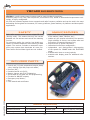
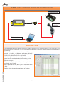
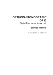
www.yptius.com
-4-
INDEX
REMOTE CONTROLS
YRC400, radio remote control...................................................................................................... 2
YRC400 HANDY radio remote control ............................................................................................ 3
HYDRAULIC MODULES
YMOD09, for dual control rods and distributors .............................................................................. 4
YIT028, for hydraulic pilot distributors and variable flow pumps ....................................................... 5
JOYSTICKS
HANDY DRIVE Handheld Control System to drive the crawler tracks of an hydraulic driven machine ..... 6
YMANP, one axis with signal outputs (small version) ....................................................................... 7
YMANP2, two axis with signal outputs (small version) ..................................................................... 8
YMANP3, three axis with signal outputs (small version)................................................................... 9
YMAS, one axis with signal outputs ............................................................................................ 10
YMAP, one axis with power outputs ............................................................................................ 11
YJS, YJP, YJC, two/three axis with signal, power or CAN outputs..................................................... 12
STABILIZERS CONTROL
YSCS, stabilizers control device with integrated functions .............................................................. 14
SLOPE SENSORS
YFSI-AN, analogic version ......................................................................................................... 15
ELECTRONIC REGULATORS
YVPC, connector version ........................................................................................................... 16
YVPP2, panel version ............................................................................................................... 17
YVPOL, octal socket version ...................................................................................................... 18
YVPUD-M, undecal socket version with double output ................................................................... 19
YSTU-PWMi, electronic regulator for multiple pwm controlled solenoids ........................................... 20
YCIVP, proportional solenoid incremental control device ................................................................ 22
ELECTRONICS AND ACCESSORIES
YPRG2, programming keyboard ................................................................................................. 23
YAIS, serial adapter for elecronic card ........................................................................................ 24
Sales and service conditions ..................................................................................................... 26
-1-
www.yptius.com
YCCS, salt spreader regulation dashboard ................................................................................... 25
YRC400 RADIO REMOTE CONTROL
YRC400 is a radio remote control system used to control hydraulic machines.
Extremely easy to use, safe, fast and precise; its electronic core, based on advanced microprocessor technology, is highly configurable.
All parts are protected against electro-magnetic and radio frequency radiation and can be used in the most
demanding and roughest environments, for cranes, platforms, power stations, oil platforms and also specific
applications.
SAFETY
MAIN FEATURES
Each radio remote control use an unique ID code
(identity code). This means that only the correct
portable unit can activate and control the matching
receiver.
For maximum safety the receiver has double processors to enable comparison and checking of data
signals. The receiver includes an automatic emergency stop system that deactivate all crane functions when received data signals are not verified.
• works with most of proportional solenoid valves
of the market (Hawe, Danfoss, etc.);
• enable only the outputs selected by the operator
(high reliability of service, less system wear and
prevention of unwanted manoeuvres);
• outputs drove by power transistors;
• customized control box configuration;
• independent and distinguished programming
of the speeds for CRANE mode and PLATFORM
mode;
• available with linear or cross joysticks;
• available with display panel for additional informations.
INCLUDED PARTS
www.yptius.com
• Central unit (CU) with proportional outputs, dump
valve, blinking light and pump unit cables;
• Receiver (RX);
• Portable control unit (PCU);
• Battery charger with 2 Ni-Cd batteries;
• Serial cable for no-radio use and programming;
• EX cable for ON/OFF outputs;
• Emergency stop button;
• Belt;
• User manual and certificates.
TECHNICAL SPECIFICATIONS
Power supply
12Vdc - 24Vdc
PCU dimensions 360x210x150 mm [14.2x8.25x5.9 in]
Available commands
Up to 8 functions
Protection class
IP65 (CU and RX), IP55 (PCU)
Outputs type
Transistor
Available blocks
MOD06, IT028
-2-
YRC400 HANDY RADIO REMOTE CONTROL
Developed for demanding environments
Young Powertech’s system is built and designed for the toughest and most demanding of environments. Young Powertech can hereby offer the market of crane and machine operators an extremely easy to use radio remote control
retaining speed, precision, and control with the maximum of safety. Behind the development of the radio remote
control systems lies the idea of providing products with a high degree of reliability, user-friendliness, and possessing good ergonomic features. The product family includes different control units, hand transmitters, and receivers
offering a variety of choice depending on the area of use. These products are based on a modular architecture,
which makes them extremely flexible to customize and adapt according to the customer’s
needs. The products – which are in high demand - are mainly mounted on cranes and mobile
machines. Our customers are some of the world’s largest and most challenging crane and
machinery manufacturers. Thousands of cranes and machines containing Young Powertech’s
radio remote control systems are in use worldwide.
SAFETY
Each radio remote control system functions in all manner of operational conditions equipped with their own unique identity code (IDcode). This means that only the correct control unit can activate and
control its matching receiver (crane/machine). For maximum safety
the receiver has double processors to enable comparison and checking of the data signals from the control unit. The receiver on the
crane operates with a socalled automatic emergency stop, i.e., dumpvalve and all of the crane movements are only activated as long as
the verified data signals are received from the actual portable control
unit. The stop function is in accordance with EN954-1 cat. 3.
• The hand-held-control (Handy-6, Handy-10 or Handy10-LCD) can be supplied with one step, two step or
with stepless infinitely variable (proportional) speed.
• The innovative push-buttons which operate with stepless
infinitely variable (proportional) speed, and remains in direct proportion to the push-buttons displacement for maximum precision and performance of the crane/machine.
• This stepless infinitely variable speed is facilitated by an innovative unique pushbutton technology design principle.
• The hand-held series has large distinct push-buttons and
can be used wearing working gloves, and the units are in
are light-weight, innovative, user-friendly and functional
in design.
• The hand-held units has stop-function for immediate
halt the crane/machines movements and functions,
are robust capsules capable of withstanding the elements and carrying out operations in the toughest and
most demanding of environments.
• The radio transmitter and its antenna are built-in. A
LED indicate functional and battery strength status as
well as providing a simple, diagnostic, trouble-shooting option.
• A shift-function option duplicates a number of functio-
•
•
•
•
•
•
ti
d iintelligent
t lli
t ffunctions
ti
ff i
flenal operations,
and
offering
xibility and a number of optional choices (PIN-code,
programmed for “momentary” or “latched”, automatic
shut-off times, e.t.c.).
20 hours operational life is guaranteed following charging. Recommended charging time is approximately two
hours. The battery (powered by two AA-batteries) are
housed inside the hand-held unit and can be easily changed by the operator.
The radio controls can be used with all of the hydraulic
valves currently available on the market.
Automatic frequency management, i.e. reliable radio
transmission, highly resistant to Interference, thanks
to frequency hopping technology to ensure interference free operation (in 433-434 MHz band). Other frequencies are available on request or to comply with
the country’s existing regulations.
Chargeable via +12/24 VDC cigarette lighter outputs,
or 110/220 VAC- transformer.
Weight: incl. battery: approx. 500 gram (depending on equipment).
Protection class : IP55
APPROVALS • Young Powertech’s radio remote control system meets the EU’s Machine- and EMC-directive (CEmark) and is approved and complies with the special demands and standards for “Remote controlled lifting devices”
in accordance with 89/336/EEC, EN954-1, EN301489, EN300 220-3, and R&TTE 1999/5/EC. The radio unit is also certified in several countries outside of Europe. Scanreco is additionally certified in accordance with EN ISO9001:2000.
-3-
www.yptius.com
MAIN FEATURES
YMOD09 PROPORTIONAL HYDRAULIC PWM MODULE
The servo control MOD09 is a block of modular hydraulic pistons, electrically controlled by a couple of proportional valves, with mechanical feedback.
The product has a high reliability thanks to careful engineering and production process carried out with the
most advanced technologies.
The installation of this block adds to a hydraulic valve the remote control, by cable or by radio. The specific
design for the dual control rods allows its installation on any type of hydraulic mechanical valve.
TECHNICAL DATA SHEET
(single module)
ELECTRICAL SPECIFICATIONS
Power supply voltage:
12 or 24Vdc
800 ÷ 1800 mA (12V)
Working current range:
350 ÷ 1000 mA (24V)
Frequency:
Working room temperature:
120 Hz
-20 ÷ +60 ºC
-68 ÷ +140 ºC
MECHANICAL AND HYDRAULIC
SPECIFICATIONS
160 [5.12]
Mechanical stroke:
± 13 [0.51] standard
Feedback:
Mechanical
Fluid type:
Mineral oil 10 ÷ 200 cSt
Max blow-by:
100 cc/minute
Max working pressure:
Max. thrust:
1300 N [290 lbs] (at 30 bar)
Weight:
200 [7.87]
1.6 kg [3,6 lbs] (approx.)
Connections:
Type
40
[1.57]
40
[1.57]
4
27
9 [0.35] [1.06]
www.yptius.com
n.4 ø9
[0.35]
6
8
9 [0.35]
9 [0.35]
-4-
30 bar [435 psi]
G1/4” BSPP
A
B
C
mm
in mm in mm in
40 1.57 182 7.16 200 7.87
46
1.81 200 7.87 218 8.58
50
1.97 212 8.35 230 9.05
40
1.57 262 10.31 280 11.02
46
1.81 292 11.50 310 12.20
50
1.97 312 12.28 330 12.99
40
1.57 342 13.46 360 14.17
46
1.81 384 15.12 402 15.82
YIT028 PROPORTIONAL BLOCK FOR SERVO-CONTROLLED HYDRAULIC MACHINES
The proportional block can be used with a remote control to
drive servo controlled hydraulic machines.
Look at it as a good alternative to add to the control system
currently installed on the machine (ex. hydraulic joysticks on
the driver’s cab).
A variation of the command current (PWM) of the coils of
the block changes proportionally its flow, moving the machine
hydraulic distributor.
Since the driver’s cab joysticks of the machine are no more,
the driver can move himself near the machine working field
(ex. to verify that the work is done correctly) or far from it
increasing his safety.
It has been designed in modular form allowing the assembly
of sections up to 8 functions.
On request it is available an exchange solenoid valve used to
select the working mode of the machine (manual or remote
controlled).
PORTABLE CONTROLLER UNIT
(to remote control)
PORTABLE CONTROLLER UNIT
(to remote control)
SERVO CONTROLLED
MACHINE
HYDRAULIC JOYSTICKS
(to control from driver’s cab)
Power supply
12V or 24V DC (+/- 10%)
Coils resistance
12V=5.1Ohm 24V=20.4Ohm
Max pressure
38 bar [550 psi]
Hysteresis
5%
Max flow
2 L/min [0.52 gal/min]
Protection class
IP65
Max current
12V=1.4A 24V=0.7A
Weight
2,5 Kg [5,5 lbs] (single section)
Frequency
120 Hz
Dimensions
40x150x150 mm [1.57x5.91x5.91 in]
-5-
www.yptius.com
TECHNICAL SPECIFICATIONS
HANDY DRIVE HANDHELD CONTROL SYSTEM TO DRIVE THE
CRAWLER TRACKS OF AN HYDRAULIC DRIVEN MACHINE
DESCRIPTION
The HandyDrive handheld control system, composed of the handeld remote control and the electronic control
unit, is designed to make simple and intuitive the
control of an hydraulic driven machine.
Moving the mini/joystick on the handle the system controls directly the four PWM outputs for
the crawler tracks: left forward/bacward and right
forward/backward.
A single or double Dump Valve is also commanded
at every movement.
CHARACTERISTICS
FOR WARD
• proportional speed adjustment and proportional steering
• separate DV for each crawler track or single DV
output, with delayed turn off.
• deadman trigger.
• emergency stop button.
• limited range for mini-joystick reference signals
to survej every failure.
• Individual adjustments for each PWM output:
• l min current
• l max current
• l raise ramp
• l fall ramp
• adjustable output frequency (from 50 to 300
Hz)
• unique supply voltage from 10 to 30 Vdc;
• card resin-encapsulated angainst vibrations and
humidity
• serial port to adjust calibration with PRG2 keyboard or PC (with specific adapter).
BACKW ARD
TECHNICAL SPECIFICATIONS
Working temperature range
DV outputs maximum
current
60 mA+load on outputs
Overall dimensions
-20 ÷ +70 °C
(+ connector)
PWM output minimum current
from 100 to 2500 mA
Drilling interaxis
119 x 99 mm (no. 4 M5 screws)
PWM output maximum current
from 100 to 2500 mA
Protection degree
IP68
Power supply
www.yptius.com
Current absorption
10Vdc ÷ 30Vdc
2.5 A
138 x 110 (+37) x 38 mm
Available PWM frequency
50-60-70-85-100-125-150-200-250-300 Hz
Time ramp up/down independently adjustable
from 0.1s to 10s
-6-
YMANP ONE AXIS POTENTIOMETRIC JOYSTICK
Pictures refer to bidirectional
version. Dimensions are valid
for both versions.
Mount with 4 self-tapping
screws with countersunk
holes on panel
(screws are supplied).
max thick
3 [0.12]
42 [1.65]
34 [1.34]
42 [1.65]
ø 3 holes
[0.12]
18 [0.70]
43 [1.69]
65 [2.56]
RUBBER BELOW
16x36 slot [0.63x1.42]
UNIDIRECTIONAL
VERSION
“YMAN-PU”
TECHNICAL SPECIFICATIONS
• Min. starting thrust: 9N [2 lbf]
• Max. applicable thrust: 80N [18 lbf]
• Max contact switch current (microswitch): 1A
(28V DC)
• POTENTIOMETER
• Resistance:10 Kohm
• Life: 10 million cycles
• Electrical angle (reduced): 100°
• Max output current (central terminal): 1mA
• Max. power: 1W
• Insulating resistance (500V DC): >1000 Mohm
• BIDIRECTIONAL VERSION
• Mechanical angle: 40° + 40° approx.
• Vout = 80% Vin (40% + 40%)
• UNIDIRECTIONAL VERSION
• Mechanical angle: 60° approx.
• Vout = 60% Vin
• BELLOW:
• Protection level: IP54
BIDIRECTIONAL
VERSION
“YMAN-PB”
80 [3.15]
(12V or 24V power supply):
• with resistance and 10V Zener diode
• UNIDIRECTIONAL version: 1.8V - 7V standard
output
• BIDIRECTIONAL version: 5V ± 3.5V output
• supplied with three wires 500 [19.7] lenght
-7-
www.yptius.com
WIRED VERSION AVAILABLE
39,75 [1.56]
7,75 [0.31]
77,0 [3.03]
YMANP2 TWO AXIS POTENTIOMETRIC JOYSTICK
Yellow
Green
Grey
White
Blue
Red
1
8
Wire colours
in wired version
69 [2.72]
1 +Vin
0.5K
0.5K
Behind
Forwards
5 NC
2K
4
1K
1K
3
2K
Right
46,5 [1.83]
Left
55,2 [2.17]
2 GND
Left
6
Right
Backwards
8 NC
0.5K
0.5K
7
In Front
78,9 [3.10]
Physical features
• Breakout force: 2.3N [0.51 lbf]
• Maximum operating force: 6 N [1.35 lbf]
• Mechanical operating angle: ±18°
• Insulation resistance at 50DC: > 50 MOhm
• Weight: 120g [0.26 lbs]
• Operating temperature range:-40 °C ÷ +70 °C
-140°F ÷ 158°F
• Environmental rating: IP65
• Connector: Panduit Mascon 2.54mm 8p
Potentiometers electrical features
• Overall resistance: 0.5 kOhm (between pins 1
and 2)
• Max power supply (Vin): 30 VDC
• Middle output voltage (Vout): 50% Vin (± 1%)
• Min output voltage (Vout) = 27% Vin (± 1%)*
• Max output voltage (Vout) = 73% Vin (± 1%)*
www.yptius.com
* Values achieved with a load of 7.5K towards Vin/2
NO contact electrical features
• Max current: 200mA (resistive load)
• ON/OFF contact activation angle: 2° (in each direction)
• Life:
10 cycles (with a 200 mA current)
5x10 cycles (with a 10 mA current)
Order code:
A1000380401 without wires
A1000380404 with 500 [19.6] wires
-8-
39,75. [1.56]
7,75. [0.31]
77,0 [3.03]
.
YMANP3 THREE AXIS POTENTIOMETRIC JOYSTICK
1
Wire colours
in wired version
Yellow
Green
Black
Red
Brown
White
Blue
Orange
8
69 [2.72]
0.5K
1 +Vin
0.5K
0.5K
Behind
6
Right
CCW
1K
2K
5
1K
2K
1K
4
BW
2K
FW
3
CW
0.5K
8
0.5K
7
0.5K
46,5 [1.83]
Right
Left
55,2 [2.17]
2 GND
Left
In Front
Potentiometers electrical features
• Overall resistance: 0.330 kOhm (between pins
1 and 2)
• Max power supply (Vin): 30 VDC
• Middle output voltage (30vdc):50% Vin (± 1%)
• Min output voltage (Vout) = 27% Vin (± 1%)*
• Max output voltage (Vout) = 73% Vin (± 1%)*
Physical features
• Breakout force: 2.3N [0.51 lbf]
• Maximum operating force: 6 N [1.35 lbf]
• Environmental rating: IP65
• Mechanical lever operating angle: ±13°
• Mechanical handle operating angle: ±27°
• Insulation resistance at 50 : > 50 MOhm
• Weight: 120g
• Operating temperature range: -40 °C ÷ +70 °C
-140°F ÷ 158°F
• Connector: Panduit Mascon 2.54mm 8p
* Values achieved with a load of 7.5K towards Vin/2
NO contact electrical features
• Max current: 200mA (resistive load)
• ON/OFF contact activation angle: +/- 1° (X and
Y axis )
• ON/OFF contact activation angle: +/- 2° (rotating handle)
• Life:
106 cycles (with a 200 mA current)
5x10⁶ cycles (with a 10 mA current)
Order code:
A1000380402 without wires
A1000380403 with 500 [19.6] wires
-9-
www.yptius.com
78,9 [3.10]
YMAS ONE AXIS JOYSTICK WITH SIGNAL OUTPUTS
DESCRIPTION
YMAS is a single axis electronic joystick with signal outputs
Joystick commands are derived from the measurement of the magnetic field produced by permanent magnets; the measurement is taken
through Hall effect probes. This kind of probes are not subject to wear
and tear.
Main characteristics:
• sturdiness;
• parabolic output signal for a better sensitivity;
• output signal stroke customizable;
• available with uni directional output (5V-0-5V) or bidirectional output
(0-5V-10V);
• “position hold” hand-grip available;
• rocker switch (unstable) on the hand-grip available;
• on/off directional outputs;
• supplied with extractable connector with screw;
• available version with two separate outputs 0-5V.
Available versions:
YMASH
xxx
x
26°
26°
x [- Cxx]
170 [6.69]
• Signal travel (in Volt tenths)
compared to rest value.
• Default value - C50 (5.0 Volt)
R = Back to the center
F = Frictioned
505 = output with 0V rest value
5F5 = floating on rest - two 0-5V
outputs on distinct wires
010 = output with 5V rest value
Ex: YMAS-010-AR-C35, with simple rod, not frictioned, centered to 5V and 3.5V travel
115 [4.53]
A = Simple rod
M = Handgrip with balanced buttons
10
1
1
71
[2.79]
www.yptius.com
TECHNICAL SPECIFICATIONS
Power supply voltage
10 ÷ 28 Vdc
Working temperature range
-20 ÷ 50 °C [-60 ÷ 122 °F]
Proportional output
+5 ÷ 0 ÷ +5 Vdc or 0 ÷ 5V ÷ 10 Vdc (max 10 mA)
Maximum output voltage
Power supply - 2.5V
ON-OFF directional signal
Positive outputs of 500 mA (max)
Connector type
Extractable conn. with screw (1.5 mm2 max section)
Mechanical stroke
± 26 degrees
Force on handle at stroke end
20 N [4.5 lbf]
- 10 -
10
15
[1.38]
YMAP ONE AXIS JOYSTICK WITH POWER OUTPUTS
DESCRIPTION
MAP is a single axis electronic joystick with PWM outputs, able to directly control a couple of solenoid valves with PWM outputs proportional to
handle movements.
Joystick commands are derived from the measurement of the magnetic field produced by permanent magnets; the measurement is taken
through Hall effect probes. This kind of probes are not subject to wear
and tear.
Main characteristics:
• one proportional section (A+B) direct control (2 PWM outputs);
• adjustable minimum/maximum current for each directions (A+B);
• adjustable rise/fall ramp time from 0.1 to 5 seconds;
• adjustable PWM frequency to 70 to 350 Hz;
• “position hold” hand-grip available;
• rocker switch (unstable) on the hand-grip available;
• “in progress manoeuvre” on/off output;
• extractable connector with screw.
x
x
R = With spring return
F = Position Hold
A = Simple knob
M = Hand-grip with rocker switch
SR =
AR =
SA =
Coils OFF at
Coils ON at
Coils always ON
neutral position neutral position
170 [6.69]
xx
115 [4.53]
YMAPH
26°
26°
Available versions:
15
[1.38]
71
[2.79]
Power Supply Voltage
10 ÷ 28 Vdc
Working Temperature Range
-20 ÷ 50 °C [-60 ÷ 122 °F]
PWM Output Minimum Current
from 100 to 2500 mA (200 mA preset)
PWM Output Maximum Current
from 100 to 2500 mA (800 mA preset)
PWM Frequencies
from 70 to 350 (120 Hz preset)
ON/OFF Output Maximum Current
500 mA
Connections
Extractable conn. with screw (1.5 mm2 max section)
Working Angle
± 26 degrees
Force on handle at stroke end
20 N [4.5 lbf]
- 11 -
www.yptius.com
TECHNICAL SPECIFICATIONS
YJS/YJP/YJC TWO AND THREE AXIS JOYSTICK WITH
SIGNAL, POWER OR CANBUS OUTPUTS
DESCRIPTION
T
Two
and
d th
three axis
i proportional
ti
l jjoysticks
ti k can b
be used
d iin a llarge variety of applications where is necessary to have a simple and reliable
user interface to control construction machinery.
• YJS (with signal outputs, available also in ratiometric version) can
only be used together with a logic control unit (PLC) or a power
control device (PWM driver).
• YJP (with PWM outputs) can directly control hydraulic devices
(pumps, distributors, dump valve) becoming often the only control
unit of the whole machine.
• YJC thanks to its inputs, can collect a large numbers of control
signals and transmit them through a CANbus network.
Designed and specifically conceived to reduce the amount of installation work, our joysticks are manufactured with top quality parts.
The control electronics is located inside the housing and to assure
extreme tightness.
Joystick movements are derived from the measurement of the magnetic field produced by permanent ferro magnets; the measurement is taken through redundant Hall effect probes. This kind of
probes are not subject to deterioration.
The configuration and calibration easiness makes these joysticks suitable for different applications.
The push button panel is completely customizable.
YA
ZA
Here are some of the available options for the three models:
• “virtual cross” to forbid diagonal movements.
• linear or parabolic output curve.
XB
XA
• standard or capacitive dead man switch.
• adjustable dead band, independently for each semi axis.
• THUMBWHEEL, to have third proportional axis.
YB
ZB
• Outputs lock if the hand-grip is not in neutral position at joystick
turn on.
• Dump valve output with delayed turn off, to avoid high pressure spikes in the hydraulic crcuit.
• Offset to compensate the hydraulic distributor dead band.
• Auxiliary output activated with logic and command levels user defined (software configurable).
• Two or three speed sets allow to regulate speed according to the machine configuration.
• Combination with only one proportional PWM output with many directional ON/OFF outputs
• Tracked machines driving function, to directly control two pumps of an hydraulic driven machine with the
up/down and left/right joystick movements (virtual 45° axis rotation).
• Dead man switch functionality active only with joystick in neutral position.
• Auxiliary inputs/outputs can be active high or active low (software configurable).
www.yptius.com
All the joystick have a FAULT output which is driven low if a failure occurs. The LEDs on the bottom side helps
the user to check the correct joystick functionality and connections.
Analog current outputs are feedback controlled. ON/OFF outputs are protected against short-circuits.
All the joysticks have a serial port to connect PRG2 serial programming keyboard (provided apart) to configure and calibrate the product.
All the joysticks are provided by default with 50 cm upnpluggable cable but is possible to require a customized wiring
- 12 -
YJS/YJP/YJC TWO AND THREE AXIS JOYSTICK WITH
SIGNAL, POWER OR CANBUS OUTPUTS
YJS
YJP
Power Supply Voltage
Max current absorption
10Vdc ÷ 30Vdc
60 mA + output load
(max 2.5 A)
Working Temperature Range
Output Signals
Input Signals
Connections
Under Panel Size
3 analog signals
range 0 ÷ 5V, 0 ÷ 10V,
ratiometric (Danfoss)
Imax: 10 mA
8 2.5A power outputs
usable as:
6 directional outputs
1 DUMP VALVE output
3 PWM pairs
1 BYPASS output
1 FAULT output
or
1 PWM output
6 ON/OFF directional
outputs
1 DUMP VALVE output
Imax: 300 mA
(for each output)
PWM outputs:
Imin: 100÷2500 mA
Imax: 100÷2500 mA
Freq: 50÷300 Hz
60 mA + ON/OFF
output load (max 1.4A)
CANH - CANL
CAN 2.0B
up to 1 Mbps
1 ON/OFF output
controllable via CAN
700 mA max
1 output for push
button power supply
voltage
(5 Vdc stabilized)
Imax: 30 mA
(usable also as 700 mA
ON/OFF output)
1 ON/OFF input usable as:
• - speed selection input
• - movement enable (dead man switch)
• - X or Y axis commutation to the Z axis
Via CAN transmittable:
- 2 ON/OFF inputs
(one usable as pickup
input)
If not used, FAULT and BYPASS outputs can be
used as ON/OFF inputs (they are bidirectional
signals).
5 analog inputs,
range: 0V ÷ 4.5V,
2.5V centered, usable
to read 5 push button
or 10 bilateral buttons
(two usable as 4-20mA
analog inputs)
Range: 0.5V ÷ 4.5V
-
-
11 kOhm towards 2.5V
Molex minifit Jr. 4 poles
Molex minifit Jr. 14 poles
with 50 cm [19.6 in]
with 50 cm [19.6 in] cable
cable
(CAN and power supply)
Molex minifit Jr.10 poles
with 50 cm [19.6 in]
cable for optional
inputs/outputs
diameter 80 mm [3.15 in] - depth 90 mm [3.54 in]
+/- 18°
Working Angle
Max force on handle
Electromagnetic Compatibility (EMC)
60 mA + output load
(max 10A)
-20 ÷ +60 °C • -68° ÷ +140°F
Thumbwheel Input Signal
Analog Inputs Impedance
YJC
800 N [180 lbf]
according to EN 13309 and EN ISO 14982 regulations
Ingress Protection Rating
IP65 (IP40 with Thumbwheel)
- 13 -
www.yptius.com
TECHNICAL SPECIFICATIONS
YSCS STABILIZERS CONTROL DEVICE
173 [6.82]
SCS
Stabilizers Control Unit
POWER
DV
ENABLE
295 [11.61]
DESCRIPTION
The SCS device is a stabilizers control unit integrated with some auxiliary functions useful for the control of
cranes installed on trucks. The core of the unit is a microprocessor based electronic card for the advanced
control of the machine, which makes available in one device the following features:
BYPASS INTERFACE: control the NO dump valve with a signal compounded of the safety electric signal
from the radio remote control and from the torque limiter, maintaining the origin safety characteristics.
The NO valve can be commanded both from the remote control and from safety devices installed on the
machine (ex. torque limiter).
STABILIZERS CONTROL: verify the correct position of the stabilizers and, if the platform is inserted,
enable the crane to work only when they are all extended and correctly positioned.
STABILIZERS BLOCK: class 3 control that avoids the movements of the stabilizers when the main
arm of the crane exceeds the horizontal slope. The stabilizers are blocked with a NO valve when their distributor is separated from the crane distributor, or with a NC valve when the stabilizers are commanded
by the same distributor of the crane.
SPEED REDUCTION: if this function is not executed by the radio remote control, reduce the speeds of
the manoeuvres when the platform is inserted on the crane; the speed reduction is realized through a
flow reduction valve.
TECHNICAL SPECIFICATIONS
Power supply voltage
www.yptius.com
Working temperature range
10Vdc ÷ 28Vdc
-20 ÷ +70 °C • -68 ÷ +158 °F
Protection class
IP65
Control unit dimensions
191 x 167 x 75 mm [7.52x6.57x2.95 in] (aluminium box)
Overall dimensions
295 x 173 x 135 mm [11.61x6.82x5.32 in] (box with connector attached)
Output current
max 2.5A for each outp
Current absorption
500 mA + output loads (blade fuse of 7.5A)
- 14 -
YFSI-AN ANALOGIC SLOPE SENSOR
DESCRIPTION
The FSI-AN sensor is a slope analog transducer with 4÷20mA current output.
It is a transducer with 3 wires:
I=4 ÷20mA
2
1
(+) Positive
power supply
-105°
+105°
R
0°
I = 4 mA
(-) Negative
power supply
The output current is proportional to
the inclination of the sensor compared to the horizontal position (see
picture).
(mA)
I = 12 mA
I = 20 mA
20
18
16
14
12
10
Working:
Supply the sensor and read the output current (directly with a milliamperometer or connecting it to a
PLC with 4÷ 20mA current input).
8
6
4
-1 0 0 ° -8 0 ° -6 0 ° -40° -20°
0°
20°
40°
60°
80° 100°
Attention: the input resistance of the used instrument (for the measurement) must have a value that allows to the sensor to supply the maximum current.
The maximum output tension of the sensor is “Vsupply - 5.5V“.
Fitting
When you have positioned the sensor, with the long side perfectly in horizontal position, it has an output current value between 11.9mA and 12.1mA. During the fitting, it is necessary to verify that the output current,
in horizontal position, is between the upon mentioned values. Otherwise, you have to act on the support
slots to place the sensor in a correct way.
TECHNICAL SPECIFICATIONS
-105° to +105°
Resolution
1.16°
Current absorbed with
output disconnected
18mA at 12VDC,
20mA at 24VDC
Max output voltage drop
5.5V
Answer time
164 ms
-10°C ÷ +70°C
-40°F ÷ +158°F
Working temperature
Precision @ Tamb
0°÷70°C • 32°÷158°F
Precision @ Tamb
-10°÷70°C • -50°÷158°F
Protection class
35
[1.38]
10
[0.39]
Max. deviation
from vertical: 5°
30°
± 1.4°
± 4.0°
80 [3.15]
IP 67
* Specifications and drawings for ±105° version
- 15 -
40 [1.57]
35
[1.38]
www.yptius.com
Working range From
10
[0.39]
10 [0.39]
10 ÷ 32 VDC
50 [1.97]
Supply voltage
YVPC ELECTRONIC REGULATOR FOR PWM CONTROLLED SOLENOID
1 Positive 24 - 12 Vdc ±10%
2 Negative
3 Input signal 0÷10 Vdc
78,5 [3.10]
29 [1.14]
3
57 [5.25]
1
2
DIN 43650
36 [1.42]
30 [1.18]
78,5 [3.10]
39 [1.54]
I (A)
-
23,5
[0.73]
I (A)
+
DZ
R
t (s ec)
t (s ec)
POT
RISE RAMP
FALL RAMP
3
GAIN
(I max)
BIAS
(I min)
1
2
This electronic regulator is made to work in
open loop control system. It has been designed
to control the current that flows in the coil of a
solenoid valve proportionally to an analog input
signal. The electronic card is contained in a box
that works as connector too.
PWM
frequency
TECHNICAL SPECIFICATIONS
Supply voltage
24 - 12 Vdc
Voltage input signal range
0 - 10 Volt (0 - 5V)
Input impedance
100 Kohm
www.yptius.com
Max current adjustment range 1A (24Vdc) 2A (12 Vdc) 20 - 100%
Bias adjustment range
0 - 30%
Rise time ramp adjustment
0 - 3 sec
Fall time ramp adjustment
0 - 3 sec
Ramps are linear and independent
PWM frequency set at 120 Hz (adjustable)
50 ÷ 400 Hz
Working room temperature
-10 C ÷ +50 C • -50°÷122°F
- 16 -
YVPP2 ELECTRONIC REGULATOR FOR PWM CONTROLLED SOLENOID
TECHNICAL SPECIFICATIONS
VPP
4
5
Supply voltage (Vsup)
10.5 ÷ 30 VDC
Panel potentiometer
5KOhm - 330°
Max output current
2.5A
Max current gap (Imax - Imin) 1.5A
Max power
75W
Ramp time adjustment
0.1 ÷ 5 sec
Indirect current measure
1V = 1A
PWM frequence
120 Hz (adjustable from 50 to 330 Hz)
Working temperature
-10 °C ÷ +60 °C • -50°÷122°F
Weight
250 g [0.55 lbs]
Back panel dimensions
85x47x86 mm [3.35x1.85x3.39 in]
Max panel thickness
10 mm [0.39 in]
Special version available with IP67 potentiometer
6
3
7
8
2
9
1
0
10
33 [1.30]
DESCRIPTION
ø4[0.15]
=
86 [3.38]
=
ø8[0.31]
50 [1.97]
YVPP2 electronic regulator is designed for single solenoid proportional
valve open loop control. Current regulation potentiometer is connected and assembled yet on electronic regulator. Current range (offset
and gain), ramps times and PWM frequency can be modified through
trimming potentiometer (placed on the back side of card) to meet different kind of valves specifications. YVPP2 is protected against supply
overtension and polarity inversion. PWM output is protected against
short-circuit. Electronic card is epoxy resin protected.
INSTALLATION
ø17
[0.67]
You can mount the regulator on panel through two countersunk screws
M4x10 (included). In the picture on side is showed front panel dimensions and drills mask. With VPP2 regulator is also included a sticker
with graduated scale from 0 to 10. You can use this sticker as reference
scale for potentiometer adjustment.
Panel
Trimming
potentiometers
Sticker with
graduated scale
Connector 10 terminals
Epoxy resin
Knob
+
s
POT
Supply
+
NC
-
Negative
Proportional
valve
measure measure +
1
1
2
3
4
5
6
7
8
9
10
1
2
3
4
5
6
7
8
9
10
10
I max (gain)
Rise ramp
Fall ramp
Frequency
+ Measure point
LED
VDXXXX
Supply
Signal
Current
- Measure point
Serial Nr.
- 17 -
www.yptius.com
Positive
YVPOL ELECTRONIC REGULATOR FOR PWM CONTROLLED SOLENOID
36 [1.42]
VPOL
VPOL
+5V out
I MIN
5
10K
I MAX
RAMP
4
0 ÷ 5V
P1
P1
RAMP
ON
OFF
3
6
P2
P3 P4
PIN 8 =
DISABLE
2
7
P2
P3 P4
PIN 8 =
ENABLE
GND out
1
+
enable/disable
(optional)
8
VDC
77 [3.03]
VP
10.5V ÷ 30V
Imax: 2.5A
+
SUPPLY
BOTTOM VIEW
SIGNAL
OUTPUT
Current measure
1V / 1A
79 [3.12]
Positive
supply
7
6
Enable/Disable
(optional)
8
5
1
4
2.5K ÷ 25K
potentiometer
3
2
Negative
supply
Proportional
solenoid
valve
www.yptius.com
TECHNICAL SPECIFICATIONS
Power supply
from 10.5 to 30 Vdc
Reference signal
0÷10V max (optional 4÷20 mA)
Reference input impedance
20 kOhm
potentiometer supply
4.6 V
Max output current
2,5 A
Ramp range regulation
0 - 5 sec (separate rise/fall)
PWM frequency
50 ÷ 250 Hz (preset to 120 Hz)
Room working temperature
-10°C ÷ +60 °C • -50°÷140°F
Indirect current measure (test point on panel)
1V read every 1A output current
Enable/Disable optional input
Vsupply commanded
- 18 -
LED on panel for:
- Supply
- Output current
- Input signal
Potentiometer for:
- Offset current (Imin)
- Gain (Imax)
- Ramp rise
- Ramp fall
- Frequency (inside)
YVPUD-M ELECTRONIC REGULATOR FOR TWO PWM CONTROLLED SOLENOIDS
TECHNICAL SPECIFICATIONS
Imin
Imax
B
Ramp
10Vdc ÷ 30Vdc
Input signal range:
-5V ÷ +5V or 0V ÷ 10V or ¼ ¾Vsupply
Max output current:
2.5 A
External potentiometer sup-5V and +5V (max 10 mA)
ply:
OUT
IN
Power supply voltage:
POWER
Input signal impedance:
VPUD-M
Imin
Imax
A
Ramp
IN
OUT
Current measure
1V / 1A
11 kOhm
Indirect current measure
1V / 1A
(test point on panel):
Working temperature ran-20 ÷ +50 °C • -68° ÷ 122°F
ge:
Independent regulations for min current (offset),
each solenoid
max current (gain) and rise/fall timeramp.
Undecal type housing for DIN guides mounting
Overall dimensions:
79 x 36 x 77 mm [3.11 x 1.41 x 3.03 in]
Weight:
200 g [0.44 lbs]
WORKING DESCRIPTION
The YVPUD-M electronic regulator is designed to command two proportional solenoids with one reference
signal. Solenoids are controlled (PWM) with feedback signal so that linearity between output current and
input signal is guaranteed and working is independent from external elements (supply voltage, temperature,
etc.). The working frequency (PWM) is set to 120 Hz but it is adjustable from 50 Hz to 330 Hz).
The regulator can be commanded by a potentiometer (the supply voltage ±5V are present) but 0 to 10V or
¼ ÷ ¾ Vsupply signals can be utilised (coupling with a PLC). Outputs cannot be active contemporaneously,
interlocked by a control circuit.
Minimum (BIAS) and maximum (GAIN) currents and rise/fall ramps are independently adjustable. Ramps
are adjustable (between 0.1 and 5 seconds) and disabled by a positive signal connected to the proper input
terminal. Red LEDs on panel show input signals variation and current variation to the solenoids, signalling if
the output circuit is interrupted.
The regulator is protected against voltage reversal and output short circuits.
B
6
5
8
4
3
9
2
11
- +
79 [3.11]
- 19 -
RIF
10
1
36 [1.41]
-5V
7
+5V
pot.
10K
B
A
www.yptius.com
77 [3.03]
A
YSTU-PWMI ELECTRONIC REGULATOR FOR MULTIPLE PWM CONTROLLED SOLENOIDS
DESCRIPTION
PROGRAMMIN
STU-PWM electronic card is a regulator
for proportional solenoid valves, which
can drive up to 8 modules (8+8 PWM outputs), starting from analog inputs (input signal range from 0 to 5V). If the
inputs analog signals are generated from
potentiometric joysticks, the control card
provides a stabilized 5V supply to power
them.
G STEPS
Star
t Current
Stop Curren
t (fast)
Stop Curren
t (slow)
Ris
e Ramp
STU-PWM
FallRamp
INPUTS
• n°
° 8 analog
l
iinputs
t signals
i
l ((range ffrom
0 to 5V);
• n° 1 enable input defined as CONTROL
PANEL ON;
• n° 2 ENABLE inputs with different operating features;
• n° 1 input to select LOW/HIGH
SPEED(optional);
• n° 3 ON/OFF inputs, directly carried to
three power outputs;
OUTPUTS
•
•
•
•
n° 8+8PWM outputs, to drive proportional solenoid valves (a pairoutputs for each analog inputs);
n° 1 DUMP VALVE output drived by all manoeuvres;
n° 1 FAULT output;
n. 3 ON/OFF outputs, directly drived by three ON/OFF inputs (max 2.5A);
OUTPUTS
Adjustable
Adj
bl PWM ffrequency, min/max
i /
output currents and
d rise/fall
i /f ll time
i
ramps. A
As option,
i
STU
STU-PWM
PWM iis avaii
lable with two selectable maximum speed sets (LOW/HIGH SPEED), to operate a different maximum speed
in different operating conditions.
It is also available a DUMPVALVE output that is turned on when a manouvre turns on. This output has a
programmable delay on switch off, to avoid elevated pressure spikes in the hydraulic circuit.
The control unit provides three ON/OFF input/output to drive directly solenoid valves, starting from low power command signal.
www.yptius.com
To ensure more safety during working mode, the electronic card provides:
-
programmable deadband, electrical stroke and adjustable signal threshold;
an overall relay, feedback controlled, supply all control unit’s outputs;
three inputs ENABLE signals (CONTROL PANAL ON, ENABLE1 and ENABLE2)
an output to control theDUMP VALVE;
an output (FAULT) to drive a warning light or a relay that report errors on analog inputs.
- 20 -
YSTU-PWMI ELECTRONIC REGULATOR FOR MULTIPLE PWM CONTROLLED SOLENOIDS
256 [10.08]
PROGRAMMING STEPS
Start Current
Diagnostic and
programming display
Stop Current (fast)
Stop Current (slow)
Fall Ramp
210 [8.27]
Rise Ramp
STU-PWM
Connector for programming and calibration
connector
45
[1.77]
56 ways
(optional)
4
5
6
7
8
-
4
5
6
7
8
functions
functions
functions
functions
functions
(4+4
(5+5
(6+6
(7+7
(8+8
Order codes for STU-PWM control unit (without connector):
Code: PSCH45i _ _
R with two speed sets
PWM outputs)
PWM outputs)
PWM outputs)
PWM outputs)
PWM outputs)
Power supply voltage
10Vdc ÷ 30Vdc
Current absorption
300 mA + load outputs
External potentiometers power supply voltage
+5V short circuit protected, max current 10 mA
Working temperature range
-20 ÷ +70 °C • -68° ÷ 158°F
PWM minimum current range
from 100 to 2500 mA
PWM maximum current range
from 100 to 2500 mA
Available PWM frequencies
50-60-70-85-100-125-150-200-250-300 Hz
ON&OFF outputs maximum current
2500 mA (700 mA for FAULT output)
Analog inputs impedance
11 KOhm towards 2.5V
Overall dimensions with connector mounted
256 x 210 x 45 mm [10.08 x 8.21 x 1.11 in]
Drill interaxis
242x242 mm [9.52x9.52 in] n. 4 holes, max dia 6 mm [0.24 in]
- 21 -
www.yptius.com
TECHNICAL SPECIFICATIONS
YCIVP PROPORTIONAL SOLENOID INCREMENTAL CONTROL DEVICE
OPERATION
The CIVP card
Th
d can b
be considered
id
d lik
like an ELECTRONIC POTENTIOMETER
It can be used to replace a potentiometer with the further possibility to have several control working
positions at the same time.
FEATURES
•
•
•
•
•
•
•
•
Voltage output signal 0 ÷ 5V, and current output signal 4 ÷ 20 mA.
Output regulation by a pair of push buttons.
Easy to command from several control working positions at the same time (simply with the
connection in parallel of the others push buttons pairs)
At the start-up the output can take the last set value or zero.
Automatic increase/decrease, if the regolation button is
held pushed, with the possibility to choose between two
different speed.
On the frontal panel some leds show the output and the
control push buttons state.
Available with proportional solenoid valve direct PWM
output (mod.CIVPP)
WIRE DIAGRAM
SUPPLY
NEGATIVE
0 ÷ 5V
Main
position
control
INC
Secondary
position
control
INC
CIVP
4 ÷ 20 mA
DEC
PV
PWM output
mod. "CIVPP"
DEC
www.yptius.com
TECHNICAL SPECIFICATIONS
Power supply voltage
10 Vdc ÷ 30 Vdc
Voltage output signal
0 ÷ 5V - Max current: 5 mA
Current output signal
4 ÷ 20 mA
Output signal resolution
256 levels
Output signal stability
< 0.5%
Working room temperature
-20 ÷ +60 °C • -68° ÷ 140°F
Case
Plastic box with Undecal connector
Overall dimensions
79 x 36 x 77 mm [3.11 x 1.42 x 3.03]
Weight
200 g [0.44 lbs]
- 22 -
YPRG2 PROGRAMMING KEYBOARD
DESCRIPTION
Th PRG2 k
The
keyboard
b
d iis th
the simplest
i
l td
device
i th
thatt can b
be used
d tto ttune working
ki
parameters
t
on th
the llast-generat
tion electronic cards developed by manufacturer.
With PRG2 keyboard and the help of the two-digit display mounted on the electronic card to be programmed,
or the flashing LED on the PRG2, you will be able to scroll all the working parameters and the tune them at
will.
500 [19.68]
At the end of the programming phase, it is necessary to save
parameters in memory by pushing contemporaneously the
PREV and the NEXT buttons, otherwise all the modifications
will be lost when the device will be turned off.
PRG2 keyboard connector can be plugged in and pulled out
from his socket on the electronic card even with the system
turned on.
The presence of the programming keyboard will be automatically detected and the device will go in programming
mode.
The LED shows, with a series of flashes, the current programming step.
WORKING SPECIFICATIONS
Increase the value of the current parameter.
(For some of the parameters, to see the value displayed
changing, you have to push the button 2 or more times.)
LED
PRG2
Push “+” and NEXT together to send a CALIBRATE command
PREV
NEXT
Go to the next parameter.
(once reached the last parameter, restart from the first)
Push PREV and NEXT together to send a SAVE command
Go to the previous parameter.
(once reached the first parameter, stay there)
ACTUAL SIZE
“+”, “-”, “PREV” and “NEXT” keys have the autorepeat
function that starts 1/2 sec. after they have been pressed.
For more complex needs (extended access mode to reserved parameters, uploading of the entire set of parameters to download to other cards, parameter’s value direct introduction, 16x2 LCD display visualization,
advanced diagnostics,...) it is available thePCPS serial programmer.
- 23 -
www.yptius.com
Decrease the value of the current parameter.
For some of the parameters, to see the value displayed
changing, you have to push the button 2 or more times.)
YAIS SERIAL INTERFACE ADAPTER FOR ELECTRONIC CARDS
STU electronic card
YJS/YJP/YJC
joysticks
RS-232 Adapter
STU electronic card
DESCRIPTION
www.yptius.com
The YAIS Serial Interface Adapter is the only medium to connect our electronic devices (STU electronic card
and YJS/YJP/YJC joysticks) to a PC for programming, calibration, firmware updating and working parameters
monitoring.
The communication between the device and PC is supported by SepSim, a Windows application (Win98/
Win2K/XP tested). The “Lite” version of SepSim is provided freely when the device is purchased.
With this application a device configuration can be
saved to a file and downloaded into another device.
The application requires a serial port or a USB to
RS232 converter.
The program file is self-installing and the application is
extremely user friendly.
AIS is provided with a 1,80 m [5.9 ft] long serial cable
(DB9
male/female).
On the right is showed the main page of SepSim.
- 24 -
YCCS SALT SPREADER DASHBOARD
DESCRIPTION
A
POWER
0
B
CCS
ON
ON
OFF
OFF
LUCI
MAX
DISTANZA
SPARGIMENTO
T
The
SALT SPREADER dashboard is an electronic regulator that allows you to proportionately control
and independently set spreading distance and salt
quantity, through the regulation of two PWM outputs.
There are also 3 more switches for auxiliary funT
ctions:
- one to set proportional commands to their max
value;
- one to control light system;
- one to control a bidirectional function (A-0-B).
The red led on the front panel provides informations
T
during working mode.
The dashboard is provided with cables and DIN conT
nectors for proportional solenoid valves.
On the rear side is placed a strong magnet to fix the
dashboard into the cockpit.
QUANTITA'
SALE
FEATURES
Through the PRG2 serial programming keyboard (optional) you will be able to tune minimum and maximum
current for each proportional solenoid valve; you can also choose the PWM outputs frequency (70 or 100
Hz).
On the start up the regulator controls the status of the analog signals in order to block PWM outputs if command signals are not at zero position; the system begins to work again when potentiometers are reset to
zero.
To ensure more safety during working mode, the regulator provides a threshold for input signals (in case
of a broken potentiometer);PWMoutput will be blocked if the corresponding command signal goes out of its
allowed range.
Supply Voltage
10Vdc ÷ 30Vdc
Current absorption
200 mA + output load
Working temperature range
-20 ÷ +70 °C • -68° ÷ 158°F
PWM output minimum current
adjustable from 100 to 2250 mA
PWM output maximum current
adjustable from 100 to 2250 mA
PWM frequency
adjustable: 70 o 100 Hz
ON/OFF output maximum current
5A
Dashboard size
150 x 95 x 95 mm [5.91 x 3.741 x 3.74 in]
Cables lenght
3 m [9.8 ft]
Seal integrity
indoor use only
Cockpit fixing through the magnet on the rear side of the dashboard
- 25 -
www.yptius.com
TECHNICAL SPECIFICATIONS
SERVICE CONDITIONS
Our company offers to the customers a qualified, efficient and express support by telephone or by direct
visit to the customer.
The support service can be used only by installers.
The telephone support is active every working day in office timetable.
At
•
•
•
•
the first contact you have to provide the following informations:
Type of system;
System serial number;
System special characteristics;
Accurate description of the problem and in which conditions the problem show itself.
Only a competent technician, after he tried to solve the problem by telephone and after he has estimated
the type of the defect, can authorise the shipment for the repair or the eventual shipment of a replacement
part.
We will accept rendered material only if it has been authorised in advance and it has been shipped “CARRIAGE FREE” (if not agreed in a different way).
In case of technician exit for a repair to the user, it will be always debited, beyond to a fixed right of call,
expenses of travel based on the current kilometric rates and the time used for the repair.
www.yptius.com
MAIN WARRANTY CONDITIONS
The manufacturer guarantees the good working of the equipment of own production for a period of 12
(twelve) months from the date of purchase certified by the invoice at the specified conditions below.
1. The warranty includes, of course, the change or the free repair of the parts of the equipment that have
production defects and not damages due to bad maintenance or improper use of the equipment.
2. The manufacturer can decide unquestionably on any issue about complaints and defects.
3. In the hypothesis of improper use or bad maintenance and/or in case of violation of the equipment from
users not authorised by manufacturer, the customer will loose all rights of assistance under warranty.
4. The manufacturer has no responsibility for eventual damages that, directly or indirectly, could arrive
from people or things for the missed observance of all instructions indicated on the “manual” and, especially, referring to the installation, safety, use and maintenance indications. Moreover this warranty does
not include compensation for the equipment inefficiency or stop periods of the machines.
5. The equipment will be repaired in our service center or in the nearest after sale authorised centre. Costs
and risks of transport from and to the assistance centre will be at customer charge. Please consider that
all costs referring to equipment repair and/or change, as for instance (but not only this) our service center people travelling expenses, will be completely at customer charge.
6. Every defective piece replaced not under warranty will become ownership of the customer.
7. Every defective piece replaced under warranty will become ownership of the manufacturer.
8. For assistance or requests without a well precise fault and for installation or explanation of system use
rules, already explained in the “manual”, all costs are at buyer charge.
9. If demanded, for all repaired components, will be given a copy of the technical relation with problem description, and added or replaced materials. If the repair is not possible or could be more expensive than
the sale price of the new component, the sales department will contact the customer for a new offer and
the defective material will be sent back without repair it.
- 26 -
YDIM SOFT START ENGINE DEVICE
DESCRIPTION
The DIM device can be used to start a D.C. engine, limiting the
start current.
altocomando
command
WORKING
to power supply
alla alimentazione
to engine
al carico
The device starts the engine when a contact connected to its
input is closed (or if you supply a +24Vdc to the blue wire). This
phase of start engine is defined by pulses, at controlled current,
of growing duty-cycle. So you will have a start at soft growing
speed. At 75% of the start phase, if the charge is in short circuit,
the starting will be stopped and the short circuit warning light
will be turned on.
During the starting, the medium supply voltage on the engine
allows to the battery to have a soft growing charge, cutting
some overcharge and oversupply peaks, to give longer life to
the battery, to the electric system and also to the engine.
The electronic card is totally covered by synthetic resin.
n° 3 hole s Ø 6 mm
74
62
=
20
20
=
74
CONNECTIONS
CONNECTIONS
+
+
FUSE
FUSE
ALIMENTAZIONE
COMANDO
COMMAND
2 1
RED
ROSSO
X1
+ POWERSUPPLY
BROWN
MARRONE
ROSSO
RED
BLUE
AZZURRO
NERO
ENGINE
MOTORE
ALIMENTAZIONE
COMANDO
COMMAND
2 1
1 2
X2
RED
ROSSO
X1
+ POWERSUPPLY
BROWN
MARRONE
ROSSO
RED
BLUE
AZZURRO
NERO
BLACK
X2
BLACK
DIM - 152
DIM - 242
BLACK
NERO
ENGINE
MOTORE
1 2
DIM - 152
DIM - 242
- POWERSUPPLY
ALIMENTAZIONE
BLACK
NERO
-
- POWERSUPPLY
ALIMENTAZIONE
-
ORDERCODES
PDAV-S
: Standard version, with DIN43650 + FAST-ON connectors (DIM-151/241)
PDAV-C
: Version without connectors (DIM-152/242)
Power supply voltage
from 11 to 28Vdc
Stand-by consumption
0mA
Current limit during the start phase
DIM-15x ..... about 17A at 12V
about 9A at 24V
DIM-24x ..... about 25A at 12V
about 15A at 24V
Max engine power
DIM-15x ..... 150W
DIM-24x..... 240W
Start duration time
20s
Working temperature range
(starting cycles of minimum 2 min.)
-40°C ÷ 85°C (fixed on metal support)
-40°C ÷ 60°C (fixed on plastic support)
Power supply cable
DIM-152/242 ...4.0m x 2.5 mmq
DIM-151/241 ...3.0m x 2.5 mmq
Engine cable
DIM-152/242 ...1.0m x 2.5 mmq
DIM-151/241 ...0.8m x 2.5 mmq
Command cable
DIM-152/242 ...1.5m x 1.0 mmq
DIM-151/241 ...0.8m x 1.0 mmq
Protection level (only for the device)
IP67
Overall dimensions
74 x 74 x 20 mm
- 29 -
www.yptius.com
TECHNICAL SPECIFICATIONS
YLEV201 AUTOMATIC AERIAL PLATFORM CONTROLLER
LEV-201/2 reads continuously the slope of platform with an angle transducer and it proportionally regulates the oil flow into
the two chambers of a levelling cylinder, keeping the platform in
horizontal position during every conditions of work.
The control unit has two safety by-pass outputs, these positive
(2A MAX) outputs are electronic card independent, the first one
is active when platform slope is between from - 90° to +10° and
the second is active when platform slope is between from +90°
to -10°.
Using by-pass outputs it is possible to obtain a safety circuit of
class ‘1’ in according to EN954-1 law.
Moreover this outputs protect against wrong handmade correction of platform slope.
An “Oil Request” output is activated when platform slope exceeds of 1° after reference position (in both directions).
All outputs are protected against short-circuit. Electronic card
is moulded in resin; this protection defend control unit against
water condense into the box.
LEV201/2 ELECTRICAL CONNECTIONS
A
B
Fuse
120mm
drill mask Ø 5mm
155.0mm
140.0mm
100mm
< 10° > 10°
Safety circuit
(normally positive)
116.0mm
B
Proportional
valve
62.0mm
A
Power
supply
www.yptius.com
TECHNICAL SPECIFICATIONS
Power supply voltage
10 Vdc÷32Vdc
Absorbed current (without loads)
18mA@ 12Vdc
Solenoid valves current range
from 0.3A to 1.7A
Maximum current on safety outputs
2A
Maximum current on "Oil Request" output
2A
Working temperature
-15 ÷ +70 °C
Connectors
DIN 43650/ISO-4400/6952
IP protection
IP 55
- 30 -
Proportional
valve
Oil request
output