1
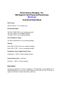
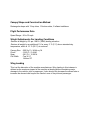
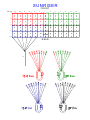
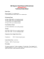
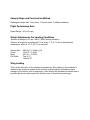
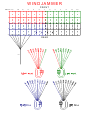
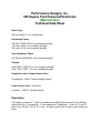
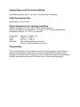
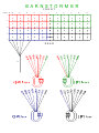
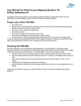
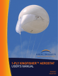
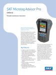
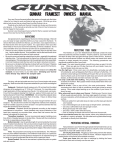
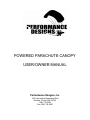
POWERED PARACHUTE CANOPY
USER/OWNER MANUAL
Performance Designs, Inc.
1300 International Speedway Blvd
DeLand, Florida USA 32724
(386) 738-2224
Fax: (386) 734-8297
Dear User/Owner;
Welcome to the world of Powered Parachute flight!
This document does not represent a complete owner’s manual for your powered
parachute system. The following information is provided as a supplement to your
ultralight owner’s manual (supplied by your ultralight manufacturer). It is not meant to be
an instructional manual on how to fly a powered parachute.
The information contained in this manual will help you understand some of the technical
terminology used, as it applies to the canopy portion of your powered parachute system.
Please take note of the care and maintenance information included, so that you may
enjoy your powered parachute for hundreds of hours of flight.
Performance Designs hopes you enjoy your canopy and that you always fly safely.
Thank you,
PERFORMANCE DESIGNS, INC.
TO THE NEW OWNER
INSTALLATION
The canopy comes with a card that is attached to the quick links for easy identification
and installation.
Take the canopy out of the plastic bag. Place the unfolded canopy on the ground
behind the machine. Unfolding the canopy carefully, locate the daisy-chained lines and
slide them out of the folds of the canopy. Do Not remove the card from the links at this
time. Do Not remove the lines from the quick links.
Stand behind the machine with your back to the machine facing the canopy with the
card and the quick links in your hand. Hold the printed part of the card facing the canopy
and the writing on the card upside down. Holding the card in this manner places the
leading edge links (front of the canopy) on the top and the trailing edge (back of the
canopy) on the bottom. Lay the card on the ground and take out the daisy chain and
resume unfolding the parachute. Turn the canopy so that as you continue to unfold it the
leading edge lines are straight leading to the top of the canopy and the trailing edge
lines are straight leading to the tail of the canopy.
Take the links off the card one at a time as you attach the canopy to the machine
following the manufacturer’s instructions.
Resume unfolding the canopy with the top skin on the ground and the bottom skin and
lines on top. Starting at the machine, take the top link and follow the lines with your eyes
making sure that the lines are leading straight to the parachute and not tangled with the
trailing lines. If they are, shake the lines lightly and the top and bottom lines will
separate.
Performance Designs, Inc.
Powered Parachute Canopy
Care and Maintenance
The canopy of your powered parachute system should be inspected before and after
each flight.
Inspection Procedure (Performed before and after each flight)
Preflight:
1. Make sure there is no debris inside the canopy by lifting at the tail and shaking
down towards the leading edge.
2. Lay the canopy flat, with the bottom surface down on a table or any clean, flat
surface. Begin at one end, visually inspecting each panel and seam thoroughly, one
panel at a time. Check for any burns, rips, tears, failed seams, etc.
3. Turn the canopy over and repeat the above procedure for the bottom surface.
Included in the inspection of the bottom surface will be the line attachments and lines
themselves.
4. Ensure that there are no twists in the line groups. Look for frayed lines. Try to
keep the lines clean. Dirt that gets into the lines abrades the lines from inside.
5. Connect the canopy to the machine ensuring that the control lines are routed
through the proper pulleys and that they travel freely. Tighten the quick links following
the manufacturers recommendations for tightness.
Post flight:
1-4. Repeat steps 1, 2, 3 and 4 above.
5. Periodically check the fabric strength after use. (See fabric information).
Your canopy can be wiped down, when needed, with a damp (not wet) soft cloth.
Avoid getting any petroleum-based substances on your canopy or lines. These agents
can do a great deal of damage!
Avoid contact with the prop and exhaust.
Fabric Information
Although the fabric used in your powered parachute is UV resistant, it has been our
experience that sunlight will have a detrimental effect on the fabric. The longer the
exposure to sunlight, the shorter the life span of the fabric. This is more noticeable on
the neon colors. Neon colors will show fading faster. Neon’s include lime green, lemon,
watermelon, and tangerine
When new the tensile strength of the fabric is specified to be 47 psi. The tear strength is
specified at 12 psi. After use, the user can check the fabric strength as follows:
1. Select a section of the top or bottom skin, as far away from seam lines as is
feasible.
2. Grasp the fabric with both hands approximately six inches apart.
3. Pull the fabric tight and apply pressure to the fabric with the thumbs; the fabric
should take some stress (20 -25 lbs. pressure). Use caution when performing
tests...fingernail and thumbnails are sharp objects and could do damage.
Factory Maintenance
Your canopy should be returned to the factory for any of the following maintenance
needs:
1. Upper suspension line replacement.
2. Any rips, tears, etc. to the canopy fabric.
3. Every 100 flight hours for a full airworthiness inspection.
4. Anytime contamination is suspected.
Performance Designs, Inc.
500 Square Foot Powered Parachutes
(Sunriser)
Technical Data Sheet
Fabric Type
Silicone coated 1.1 oz. ripstop nylon
Reinforcing Tapes
3/8" MIL-T-5038 200 lb. min. breaking strength
1/2" nylon 200 lb. min. breaking strength
3/8" nylon 150 lb. min. breaking strength
Line Attachment Tapes
3/4" MIL-W-4088 600 lb. min. breaking strength
Threads
Size E MIL-T-7807 8.5 lb. min. breaking strength
Size F MIL-T-7807 11 lb. min. breaking strength
Suspension Lines/ Upper Control Lines
Polyethylene - 825 lb. Tensile strength (upper)
Lower Control Lines - (red lines)
Polyester - 1,000 lb. Tensile strength
Description
The canopy consists of: 13 cells or chambers, 12 loaded ribs, 13 non loaded ribs, 2
Inflatable stabilizers, 16 ea A, B, C and D lines, 2 ea. AX, BX, CX, DX, E, F lines, 12
upper control lines, 2 lower control lines (red lines).
Canopy Shape and Construction Method
Rectangular shape with 13 top skins, 13 bottom skins, 2 inflated stabilizers.
Flight Performance Data
Speed Range - 26 to 30 mph.
Weight Adjustments For Landing Conditions
-Reduce all weight by 2% per 1000 ft (300M) landing elevation
-Reduce all weight by an additional 1% for every 3° C (5° F) above standard day
temperature, which is 15° C (59° F) at sea level.
Canopy Size
Chord
Span
Cell Width
- 500 Sq. Ft./ 46.44 sq. M.
- 12.60 Ft. / 3.84 M.
- 39.5 Ft. / 12.06 M.
- Top 36 ½”
Bottom 33”
Wing Loading
This is at the discretion of the machine manufacturer. Wing loading in this instance is
defined as the maximum impact of the machine at landing without sustaining major
damage to the vehicle, pilot or passenger. It also should not decrease the ascent rate or
increase the descent rate beyond the comfort zone of the pilot and passenger.
S U N R IS E R
FRONT
C ELL #
12
10
8
6
4
2
1
3
5
7
9
11
13
A3
A2
A2
A2
A2
A2
A1 AX
AX A1
A2
A2
A2
A2
A2
A3
B3
B2
B2
B2
B2
B2
B1 BX
BX B1
B2
B2
B2
B2
B2
B3
C3
C2
C2
C2
C2
C2
C1 CX
CX C1
C2
C2
C2
C2
C2
C3
D3
D2
D2
D2
D2
D2
D1 DX
DX D1
D2
D2
D2
D2
D2
D3
UST
1
UST
3
UST
5
U ST
7
UST
9
U ST
11
E1
E1
F1
F1
REAR
LST
Performance Designs, Inc.
500 Square Foot Powered Parachutes
(Windjammer)
Technical Data Sheet
Fabric Type
Silicone coated 1.1 oz. ripstop nylon
Polyurethane/Silicone blend coated 1.5 oz. ripstop nylon
Reinforcing Tapes
3/8" MIL-T-5038 200 lb. min. breaking strength
3/4" MIL-T-5608 100 lb. min. breaking strength
1/2" nylon 200 lb. min. breaking strength
3/8" nylon 150 lb. min. breaking strength
Line Attachment Tapes
3/4" MIL-W-4088 600 lb. min. breaking strength
Threads
Size E MIL-T-7807 8.5 lb. min. breaking strength
Size F MIL-T-7807 11 lb. min. breaking strength
Suspension Lines/ Upper Control Lines
Polyethylene -
825 lb. Tensile strength (upper)
Lower Control Lines - (red lines)
Polyester - 1,000 lb. Tensile strength
Description
The canopy consists of: 13 cells or chambers, 12 loaded ribs, 13 non loaded ribs, 2
Inflatable stabilizers, 16 ea A, B, C and D lines, 2 ea. AX, BX, CX, DX, E, F lines, 12
upper control lines, 2 lower control lines (red lines).
Canopy Shape and Construction Method
Rectangular shape with 13 top skins, 13 bottom skins, 2 inflated stabilizers.
Flight Performance Data
Speed Range - 26 to 30 mph.
Weight Adjustments For Landing Conditions
-Reduce all weight by 2% per 1000 ft (300M) landing elevation
-Reduce all weight by an additional 1% for every 3° C (5° F) above standard day
temperature, which is 15° C (59° F) at sea level.
Canopy Size
Chord
Span
Cell Width
- 500 Sq. Ft./ 46.44 sq. M.
- 12.60 Ft. / 3.84 M.
- 39.5 Ft. / 12.06 M.
- Top 36 ½”
Bottom 33”
Wing Loading
This is at the discretion of the machine manufacturer. Wing loading in this instance is
defined as the maximum impact of the machine at landing without sustaining major
damage to the vehicle, pilot or passenger. It also should not decrease the ascent rate or
increase the descent rate beyond the comfort zone of the pilot and passenger.
W IN D J A M M E R
FRONT
CELL #
12
10
6
8
4
2
1
3
5
7
9
11
13
A7
A6
A5
A4
A3
A2
A1 AX
AX A1
A2
A3
A4
A5
A6
A7
B7
B6
B5
B4
B3
B2
B1 BX
BX B1
B2
B3
B4
B5
B6
B7
C7
C6
C5
C4
C3
C2
C1 CX
CX C1
C2
C3
C4
C5
C6
C7
D7
D6
D5
D4
D3
D2
D1 DX
DX D1
D2
D3
D4
D5
D6
D7
UST
1
UST
2
UST
3
UST
4
UST
5
UST
7
UST
9
E2
E1
E1
E2
F2
F1
F1
F2
REAR
LST
Performance Designs, Inc.
500 Square Foot Powered Parachutes
(Barnstormer)
Technical Data Sheet
Fabric Type
Silicone coated 1.1 oz. ripstop nylon
Reinforcing Tapes
3/8" MIL-T-5038 200 lb. min. breaking strength
1/2" nylon 200 lb. min. breaking strength
3/8" nylon 150 lb. min. breaking strength
Line Attachment Tapes
3/4" MIL-W-4088 600 lb. min. breaking strength
Threads
Size E MIL-T-7807 8.5 lb. min. breaking strength
Size F MIL-T-7807 11 lb. min. breaking strength
Suspension Lines/ Upper Control Lines
Polyethylene - 825 lb. Tensile strength (upper)
Lower Control Lines - (red lines)
Polyester - 1,000 lb. Tensile strength
Description
The canopy consists of: 11 cells or chambers with Mylar stiffeners sewn to the leading
edge of the ribs, 12 loaded ribs, 11 non loaded ribs, 2 stabilizers, 12 ea A, B, C and D
lines, 2 ea. AX, BX, CX, DX, E, F lines, 12 upper control lines, 2 lower control lines (red
lines).
Canopy Shape and Construction Method
Semi Elliptical shape, with 11 top skins, 11 bottom skins, 2 stabilizers.
Flight Performance Data
Speed Range - 26 to 30 mph.
Weight Adjustments For Landing Conditions
-Reduce all weight by 2% per 1000 ft (300M) landing elevation
-Reduce all weight by an additional 1% for every 3° C (5° F) above standard day
temperature, which is 15° C (59° F) at sea level.
Canopy Size
Chord
Span
Cell Width
- 500 Sq. Ft./ 46.44 sq. M.
-12.88 Ft. / 3.93 M.
- 39.33 Ft. / 11.99 M.
- Top, Varies depending on the cell
Bottom, Varies depending on the cell
Wing Loading
This is at the discretion of the machine manufacturer. Wing loading in this instance is
defined as the maximum impact of the machine at landing without sustaining major
damage to the vehicle, pilot or passenger. It also should not decrease the ascent rate or
increase the descent rate beyond the comfort zone of the pilot and passenger.
B A R N S TO R M E R
FR O N T
C E LL # 10
8
6
4
2
1
3
5
7
9
11
A 6
A 5
A 4
A 3
A 2
A 1 A X
A X A 1
A 2
A 3
A 4
A 5
A 6
B 6
B 5
B 4
B 3
B 2
B 1 B X
B X B 1
B 2
B 3
B 4
B 5
B 6
C 6
C 5
C 4
C 3
C 2
C 1 C X
C X C 1
C 2
C 3
C 4
C 5
C 6
D 6
D 5
D 4
D 3
D 2
D 1 D X
D X D 1
D 2
D 3
D 4
D 5
D 6
U S T
1
U S T
2
U S T
3
U S T
4
U ST
5
U S T
7
E 1
E 1
F1
F1
R E A R
LS T
Performance Designs, Inc.
400 Square Foot Powered Parachutes
(Barnstormer)
Technical Data Sheet
Fabric Type
Silicone coated 1.1 oz. ripstop nylon
Reinforcing Tapes
3/8" MIL-T-5038 200 lb. min. breaking strength
1/2" nylon 200 lb. min. breaking strength
3/8" nylon 150 lb. min. breaking strength
Line Attachment Tapes
3/4" MIL-W-4088 600 lb. min. breaking strength
Threads
Size E MIL-T-7807 8.5 lb. min. breaking strength
Size F MIL-T-7807 11 lb. min. breaking strength
Suspension Lines/ Upper Control Lines
Polyethylene - 825 lb. Tensile strength (upper)
Lower Control Lines - (red lines)
Polyester - 1,000 lb. Tensile strength
Description
The canopy consists of: 11 cells or chambers with Mylar stiffeners sewn to the leading
edge of the ribs, 12 loaded ribs, 11 non loaded ribs, 2 stabilizers, 12 ea A, B, C and D
lines, 2 ea. AX, BX, CX, DX, E, F lines, 12 upper control lines, 2 lower control lines (red
lines).
Canopy Shape and Construction Method
Rectangular shape with 11 top skins, 11 bottom skins, 2 stabilizers.
Flight Performance Data
Speed Range - 26 to 30 mph.
Weight Adjustments For Landing Conditions
-Reduce all weight by 2% per 1000 ft (300M) landing elevation
-Reduce all weight by an additional 1% for every 3° C (5° F) above standard day
temperature, which is 15° C (59° F) at sea level.
Canopy Size - 400 Sq. Ft./ 46.44 sq. M.
Chord
-11.43 Ft. / 3.48 M.
Span
- 34.96 Ft. / 10.66 M.
Wing Loading
This is at the discretion of the machine manufacturer. Wing loading in this instance is
defined as the maximum impact of the machine at landing without sustaining major
damage to the vehicle, pilot or passenger. It also should not decrease the ascent rate or
increase the descent rate beyond the comfort zone of the pilot and passenger.
B A R N S TO R M E R
FR O N T
C E LL # 10
8
6
4
2
1
3
5
7
9
11
A 6
A 5
A 4
A 3
A 2
A 1 A X
A X A 1
A 2
A 3
A 4
A 5
A 6
B 6
B 5
B 4
B 3
B 2
B 1 B X
B X B 1
B 2
B 3
B 4
B 5
B 6
C 6
C 5
C 4
C 3
C 2
C 1 C X
C X C 1
C 2
C 3
C 4
C 5
C 6
D 6
D 5
D 4
D 3
D 2
D 1 D X
D X D 1
D 2
D 3
D 4
D 5
D 6
U S T
1
U S T
2
U S T
3
U S T
4
U ST
5
U S T
7
E 1
E 1
F1
F1
R E A R
LS T