1
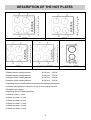
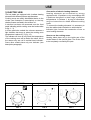
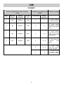
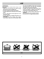
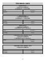
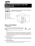
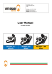
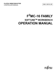
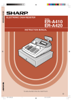
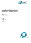
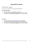
USE, INSTALLATION AND MAINTENANCE
INSTRUCTIONS FOR ELECTRICAL
BUILT-IN HOT PLATES
Dear User,
we are sincerely grateful to you for purchasing one of our products.
We are sure that the appliance is, functional and easy to use, built with the finest materials and
components and it will satisfy all your needs.
We would ask that you read the instructions within this booklet very carefully so as to enable you
to obtain quality results from the outsets.
The appliance must be installed only by a qualified electrician in compliance with the
instructions provided.
The manufacturer declines all responsability for improper installation.
The manufacturer is not responsible for any transcription errors or misprints contained in this handbook
and, furthermore, reserves the right to make any modification on the products, which might be deemed
necessary or usefull, this being in the user’s interest, without altering their basic operating or safety features.
COD.120349AEG684 - 16.01.2004
DESCRIPTION OF THE HOT PLATES
MODEL
MODEL
MODEL
61040 K
MODEL
1 Radiant electric heating element
Ø 145 mm
1200 W
2 Radiant electric heating element
Ø 180 mm
1700 W
3 Halogen electric heating element
Ø 145 mm
1200 W
4 Halogen electric heating element
Ø 180 mm
1800 W
5 Signalling layout of heating elements position and residual heat indicator
6 Indicator that signals the connection of one or more heating elements
7 Residual heat indicator
8 Signalling layout of heating elements
9 Switch for plate n. 1 front
10 Switch for plate n. 2 front
12 Switch for plate n. 4 front
13 Switch for plate n. 1 bach
14 Switch for plate n. 2 bach
15 Switch for plate n. 3 bach
2
31050 K
MODEL
USE
Connection of electric heating elements
Heating elements are controlled by energy
regulators with 12 positions or by commutators with
6 positions that permit a wide range of different
temperatures. In Scheme 1, by way of information,
we give instructions to obtain different cooking
levels.
To connect the heating elements it is necessary to
turn the relative knob clockwise or anticlockwise.
Indicator light 6 shows the connection of one or
more heating elements.
1) ELECTRIC HOB
The hot plates are equipped with 4 radiant heating
elements with different powers and diameters.
Cooking zones are easily identifiable thanks to the
circles (see illustration in description) on the top;
relative powers are listed in the scheme n.1.
A scheme has been silk-screened onto the front
panel indicating which cooking zone the knobs refers
to (fig. 1 - 3).
In some particular models the scheme annexes a
light indicator that turns on when the cooking zone
temperature is above 60° C (fig. 1-3).
The indicator will turn off only when the temperature
of the cooking zone will be below the value: this is
the reason why we call it residual heat indicator.
Some other models have only one indicator (see
description paragraph).
How to use the cooking zones
Heating takes place only in the inside part of the
circles drawn on the special glass. The circles have
to be completely covered by the pots.
61040 K MODEL
61040 K MODEL
31050 K MODEL
FIG. 1
FIG. 2
FIG. 3
3
USE
SCHEME 1
Power and dimensions of the cooking
zones
Position for regulation of the Possible cookings
knobs
Zone
n°
Diameter
in mm.
Heating
elements
Power
W
Commutators
Energy
regulators
1
145
Radiant
1200
1
1
To melt butter,
chocolate and else.
1-4
To heat small
quantities of liquid
and to keep dishes
warm.
2
180
Radiant
1700
2
3
145
Halogen
1200
3
4-8
To heat foods,
thaw deep-frozen
foods, to cook fruits
and legumes.
4
180
Halogen
1800
4
8 - 10
To cook meat, fish,
legumes
with
sauce.
5
10 - 12
To cook meat
roast, fish; to cook
steaks and eggs.
6
12
To fry with oil and
to
boil
large
quantities of water.
4
USE
WARNINGS:
For correct use, please look at fig. 4 and
remember:
- Switch on the electricity only after having
placed the pot on the cooking zone.
- Use pots and pans with flat solid bottoms.
- Use pots with the same diameter as the cooking
zones.
- Do not slide the pot on the glass as it can
damage the glass.
- Do not scrape the pot against the glass so to
not damage it.
- During the use of the cooking zones, please,
keep children away from the hot plates. Make
-
FIG. 4
5
sure that the handles of the pots are facing
towards the interior. Be aware that overheated
fats and oils may become flammable.
Cooking zones after using remain warm; don’t
place your hands or objects on the glass to
avoid burns, till the indicator light is off.
If the glass cracks, please, disconnect the
appliance.
Don’t use plastic pots or aluminum sheets.
Don’t use hob as a supplementary surface.
CLEANING
2) ELECTRIC HOB
removed using vinegar or lemon.
- Pay attention not to let spilled sugar burn onto
the element. In this case turn the switch off and
clean the surface with hot water and the razor
blade scraper.
- After a period of time metal reflex and scratches
(fig. 6) may appear due to the wrong cleaning and
the wrong use of the pots. The scratches cannot
be removed, but they do not compromise the
good operating of the hob.
- Don’t use steam jets for the equipment cleaning.
To protect the surface and maintain the clean and
bright finish, use a silicone conditioner. This will
Protect the surface whilst cooking.
It is very important to clean the surface soon after
every use, when the glass is still warm.
Do not use metallic sponges, powder abrasives or
corrosive sprays.
Depending on the dirt level we recommend:
- Slight stains: use a moist clean rag.
- Burnt or soiling may be removed with a special
razor scraper ( fig. 5 ); be aware that the razor
can cause wounds.
- Liquid marks, caused by boil-overs, can be
FIG. 5
FIG. 6
6
INSTALLATION
TECHNICAL INSTRUCTIONS FOR
THE INSTALLER
with the external perimeter of the hob.
The ends of the strip must fit together without
overlapping.
- Stick the seal to the hotplate uniformly, pressing
it with fingers.
- Take the protective paper strip of the seal off,
place the hotplate in the opening made in the
table top, and lock it with the special screws
“F”(fig. 12).
Installation may only be carried out by a
competent technician or electrician.
3) INSERTING
After having cleared out all the packing
components, make sure of the integrity of the
appliance.
Please keep children away from all packing
materials (carton, polystyrene, nails,..).
Make a cutout in the worktop, according to the
dimensions indicated in fig. 7-8; make sure the
critical dimensions of the space in which the
appliance has to be installed (fig. 9) are respected.
WARNINGS:
Be aware that the glue joining laminated plastic to
the wood, has to resist to temperatures above
150° C, to avoid delamination.
The installer should bear in mind that the mixed
appliance is the Y type. The rear wall, adjacent
and surrounding surfaces must therefore be able
to withstand temperatures above 65° C.
4) FIXING
A special sealing strip underneath the hob must be
used.
Make sure it is correctly positioned with no gaps to
avoid any water infiltration. To fit the strip in the
right way, please, respect the following
instructions:
- Fix the hooks in the relative accomodations of the body.
- Turn the hob over, take the seal strips off from
their support, taking care that the transparent
protection remains attached to the seal. Correctly
place the seal “E” (fig. 11) under the hob edge,
so that the external side of the seal fits together
COMPLY WITH THE
DIMENSIONS (mm)
A
B
C
D
2 ELEM.
285
485
57.5
57.5 100 min.
4 ELEM.
560
490
57.5
57.5 100 min.
FIG. 7
FIG. 8
FIG. 9
FIG. 10
FIG. 11
FIG. 12
7
E
INSTALLATION
5) ELECTRICAL CONNECTION
- Please do not use in the connection any
reduction, adaptation that may provoke a false
contact following dangerous overheatings.
- The outlet must be accessible after the built-in.
When the connection has been done directly to
the input system:
- Install between the appliance and the system an
omnipolar switch, adequate to the load of the
appliance, with a minimum nose between the
contacts of 3 mm.
- Keep in mind that the “earth” cable does not have
to be interrupted by the switch.
- In an alternative solution the electrical connection
can also be protected by a differential switch with
high sensitivity.
We recommend to fix the earth coloured cable to an
appropriate earth installation.
The electrical connection must be done in
accordance with all electrical and installation
requirements of the Regulation.
Before proceeding with the connection, please,
verify that:
- The power of the electrical system and the power
of the outlets is adequate to the maximum power
of the appliance (see the identification label in the
lower part of the body).
- The electrical system must be earthed according
to the Regulations. We disclaim all
responsabilities for not observing such points.
- If the appliance is not equipped with an input
cable, connect to the clamp with an adequate
sized cable (see scheme paragraph 8) keeping
the “earth” conductor longer than “live” ones,
following the scheme of fig. 13-14.
When the connection to the input system has
been done through a outlet:
- Apply to the input cable “C”, if unprovided, a
normalized plug adequate to the load indicated in
the identification label. Connect the cables
according to the scheme of fig.13-14, making sure
to respect the undermentioned respondences:
WARNINGS:
- The input cable has to be located so that it never
reaches a temperature over 75° C.
All our products are projected and built
according to the European Norms
EN 60 335-1 and EN 60 335-2-6 and relative
amendments.
The appliance has been produced according
with the European Directives:
- CEE 89/336 + 92/31 + 93/68 concerning the
compatibility electromagnetic.
- CEE 73/23 + 93/68 concerning the electrical
security.
4 HEATING ELEMENTS
2 HEATING ELEMENTS
FIG. 13
FIG. 14
Letter L1 ( Live ) = cable red colour;
Letter L2 ( Neutral ) = cable black colour;
Symbol
colour.
( Ground ) = cable green - yellow
8
MAINTENANCE
In case of substitution of the input cable, the
installer must keep the “earth” conductor longer
than “live” ones, and must respect the cautions in
paragraph “electrical connection”.
To reassemble the appliance repeat the process
inversely.
Before doing any repairs, disconnect the
appliance from the input power.
6) COMPONENTS SUBSTITUTION
To replace the components lodged in the internal
part, is necessary to remove the appliance from the
furniture, overturn it, loosen the screws and take off
the bottom.
After these actions it is possible to work on the
plates, commutators, clamps and input cable.
7) TECHNICAL CHARACTERISTICS
OF THE ELECTRICAL COMPONENTS
To facilitate the job of the installer we present a
scheme with the characteristics of the components.
POWER OF ELECTRICAL COMPONENTS DENOMINATIONS W
Denominations
W
Heating element Ø mm 145 radiant and halogen
1200
Heating element Ø mm 180 radiant
1700
Heating element Ø mm 180 halogen
1800
TYPE AND SECTION OF THE POWER CABLES 4 HEATING ELEMENTS
Cable type
Single phase power
230 - 240 V~
Rubber
H05 RR-F
3 X 2.5 mm2
TYPE AND SECTION OF THE POWER CABLES 2 HEATING ELEMENTS
Cable type
Single phase power 230 - 240 V~
Rubber
H05 RR-F
3 X 1.5 mm2
9
TECHNICAL DATA
MODEL WITH
4 HEATING ELEMENTS
(2 RADIANTS + 2 HALOGEN)
Voltage
230 - 240 V~
Frequency
50/60 Hz
Tot. Rating
5900 W
MODEL WITH
4 HEATING ELEMENTS
(3 RADIANTS + 1 HALOGEN)
Voltage
230 - 240 V~
Frequency
50/60 Hz
Tot. Rating
5900 W
MODEL WITH
4 HEATING ELEMENTS
(4 RADIANTS with 5 indicators)
Voltage
230 - 240 V~
Frequency
50/60 Hz
Tot. Rating
5800 W
CANADIAN 61040 K MODEL WITH
4 HEATING ELEMENTS
( 4 RADIANTS with 2 indicators )
Voltage
230 - 240 V~
Frequency
50/60 Hz
Tot. Rating
5800 W
CANADIAN 31050 K MODEL WITH
2 HEATING ELEMENTS
Voltage
230 - 240 V~
Frequency
50/60 Hz
Tot. Rating
2900 W
10
SERVICE AND SPARE PARTS
For Service & Parts
Phone: 1- 800 - 6788352
WWW.Euro-Parts.ca
Euro-Parts
608 Campbell street
Lucknow, ON
N0G-2H0 Canada
Fax 519-528-5001
Phone local: 519-528-5005
EURO - LINE APPLIANCES
2150 Winston Park Drive unit 20
Oakville, Ontario
L6H 5V1 Canada
Tel. 905 829 3980
Fax 905 829 3985
www.euro-line-appliances.com
or contact us at
[email protected]
11