1
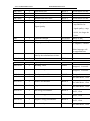
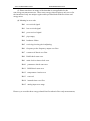
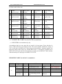
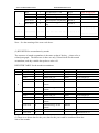
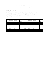
www.ultrasonicscn.com
YOUR FLOW MEASUREMENT EXPERT
Communication Protocols
LRF-2000 has an isolated serial port, the RS485.
LRF-2000 can support more than 4 different communication protocols by the same
time; include MODBUS-ASCII, ASCII-RTU, Meter-BUS, the Fuji Extended Protocol
and more than 10 compatible communication protocols used by our flow meters.
MODBUS is a very commonly used industrial protocol. Both the RTU and the ASCII
format of MODBUS is supported
The Fuji Extended Protocol is developed based on the protocol used in a Japanese
ultrasonic flow meter. It is totally compatible with that of Version 7 flow meter.
LRF-2000 can be used as a sample RTU terminal. The 4-20mA output in the
LRF-2000 can be used to open an analog proportional valve; The OCT output can be
used to control the turn-on and turn-off of other devices such as a pump. The analog
input can be used to input pressure or temperatures signals.
There is a programmable device address (or ID number) located at window M46.
When LRF-2000 is used in a network, all the parameters of the flow meter can be
programmed through the network, except the device address that needs the keypad.
At most occasions, data should be obtained by polling the flow mete with a command,
the flow meter will respond with what the master asks.
LRF-2000 can also set to automatically output data at a period which is
programmable.
The LRF-2000 also has a special command sets to facilitate the use of the flow meter
in a GSM network.
5.1 The MODBUS protocol
Both the two formats of the MODBUS protocol can be supported.
A software switch located at the window number 63(shorted as M63 after) select
MODBUS-ASCII or MODBUS-RTU will be in functioning.
The default option is MODBUS-ASCII format.
LRF-2000 can only support MODBUS functions code 3 and code 6, i.e. reading
registers and writing a register.
For example, reading the registers from REG0001 to REG0010 in the unit #1
(ultrasonic flow meter) under the MODBUS-RTU format, the command could be as
following
01
(hex)
Unit
03
Function
00
start
00
00
0A
REG
Numbers of REGs
C5
CD
Check-sum
While under the MODBUS-ASCII format, the command could be
www.ultrasonicscn.com
YOUR FLOW MEASUREMENT EXPERT
:01030000000AF2(CR and LF)
Details about the standard MODBUS protocol will not be studied in this manual;
please the users find them on other related materials.
By default, the RS232/RS485 will setup with 9600,none,8,1(9600bd,none parity,8
data bits, 1 stop bit)
5.1.1 MODBUS REGISTERS TABLE
MODBUS REGISTERS TABLE for LRF-2000
(please take notice the difference with the water meter MODBUS table)
REGISTER
0001-0002
0003-0004
0005-0006
0007-0008
0009-0010
NUMBER
2
2
2
2
2
VARIABLE NAME
Flow Rate
Energy Flow Rate
Velocity
Fluid sound speed
Positive accumulator
FORMAT
REAL4
REAL4
REAL4
REAL4
LONG
0011-0012
2
Positive decimal fraction
REAL4
0013-0014
2
Negative accumulator
LONG
0015-0016
2
Negative decimal fraction
REAL4
0017-0018
0019-0020
0021-0022
0023-0024
0025-0026
0027-0028
0029-0030
0031-0032
2
2
2
2
2
2
2
2
Positive energy accumulator
Positive energy decimal fraction
Negative energy accumulator
Negative energy decimal fraction
Net accumulator
Net decimal fraction
Net energy accumulator
Net energy decimal fraction
LONG
REAL4
LONG
REAL4
LONG
REAL4
LONG
REAL4
NOTE
Unit: m3/h
Unit: GJ/h
Unit: m/s
Unit: m/s
Unit is selected by
M31, and depends on
totalizer multiplier
Same unit as the
integer part
Long is a signed
4-byte integer, lower
byte first
REAL4 is a format of
Singular IEEE-754
number, also called
FLOAT
www.ultrasonicscn.com
YOUR FLOW MEASUREMENT EXPERT
0033-0034
0035-0036
0037-0038
0039-0040
0041-0042
0043-0044
2
2
2
2
2
2
Temperature #1/inlet
Temperature #2/outlet
Analog input AI3
Analog input AI4
Analog input AI5
Current input at AI3
REAL4
REAL4
REAL4
REAL4
REAL4
REAL4
Unit: C
Unit: C
0045-0046
0047-0048
0049-0050
2
2
2
Current input at AI3
Current input at AI3
System password
REAL4
REAL4
BCD
In unit mA
In unit mA
In unit mA
Writable。00H for
unlock
0051
1
Password for hardware
BCD
Writable。“A55Ah”
for unlock
0053-0055
3
Calendar (date and time)
BCD
Writable。6 Bytes of
BCD stands
SMHDMY,lower
byte first
0056
1
Day+Hour for Auto-Save
BCD
Writable。For
example 0512H
stands Auto-save on
12:00 on 5th。0012H
for 12:00 on
everyday。
0059
0060
1
1
Key to input
Go to Window #
INTEGER
INTEGER
0061
1
LCD Back-lit lights for number of
seconds
INTEGER
Writable
Writable。
Writable。In unit
second
0062
1
Times for the beeper
INTEGER
0062
1
Pulses left for OCT
INTEGER
0072
0077-0078
0079-0080
1
2
2
Error Code
PT100 resistance of inlet
PT100 resistance of outlet
BIT
REAL4
REAL4
Writable。Max 255
Writable。Max 65535
16bits, see note 4
In unit Ohm
In unit Ohm
www.ultrasonicscn.com
YOUR FLOW MEASUREMENT EXPERT
0081-0082
0083-0084
0085-0086
0087-0088
0089-0090
0092
2
2
2
2
2
1
Total travel time
Delta travel time
Upstream travel time
Downstream travel time
Output current
Working step and
REAL4
REAL4
REAL4
REAL4
REAL4
INTEGER
Signal Quality
In unit Micro-second
In unit Nino-second
In unit Micro-second
In unit Micro-second
In unit mA
The high byte is the
step and low for
signal quality,range
00-99,the larger the
0093
0094
0096
1
1
1
0097-0098
2
0099-0100
Upstream strength
Downstream strength
Language used in user interface
INTEGER
INTEGER
INTEGER
REAL4
2
The rate of the measured travel
time by the calculated travel time.
Reynolds number
0101-0102
0103-0104
2
2
Pipe Reynolds factor
Working Timer
REAL4
LONG
0105-0106
2
Total working time
LONG
0105-0106
0113-0114
2
2
Total power on-off time
Net accumulator
LONG
REAL4
0115-0116
2
Positive accumulator
REAL4
0117-0118
2
Negative accumulator
REAL4
0119-0120
2
Net energy accumulator
REAL4
0121-0122
2
Positive energy accumulator
REAL4
0123-0124
2
Negative energy accumulator
REAL4
0125-0126
2
Flow for today
REAL4
better.
Range 0-2047
Range 0-2047
0 : English,1:Chinese
Other language will
be supported later
Normal 100+-3%
REAL4
unsigned,in second
unsigned,in second
Unsigned
In Cubic Meter,float
In Cubic Meter,float
In Cubic Meter,float
In GJ,float
In GJ,float
In GJ,float
In Cubic Meter,float
YOUR FLOW MEASUREMENT EXPERT
www.ultrasonicscn.com
0127-0128
2
Flow for this month
REAL4
0129-0130
0131-0132
2
2
LONG
REAL4
0133-0134
0135-0136
2
2
0137-0138
0139-0140
0141-0142
0143-0144
2
2
2
2
0145-0146
0147-0148
0158
0165-0166
0173-0174
2
2
1
2
2
Manual accumulator
Manual accumulator decimal
fraction
Batch accumulator
Batch accumulator decimal
fraction
Flow for today
Flow for today decimal fraction
Flow for this month
Flow for this month decimal
fraction
Flow for this year
Flow for this year decimal fraction
Current display window
Failure timer
Current output frequency
0175-0176
2
Current output with 4-20mA
REAL4
0181-0182
2
Temperature difference
REAL4
0183-0184
2
REAL4
0185-0186
0187-0188
0189-0190
0191-0192
0221-0222
0229-0230
0231-0232
0233-0234
0257-0288
0289
0311
2
2
2
2
2
2
2
2
32
1
2
Lost flow for period of last power
off
Clock coefficient
Total time for Auto-Save
POS flow for Auto-Save
Flow rate for Auto-Save
Inner pipe diameter
Upstream delay
Downstream delay
Calculated travel time
LCD buffer
LCD buffer pointer
Worked time for today
REAL4
REAL4
REAL4
REAL4
REAL4
REAL4
REAL4
REAL4
BCD
INTEGER
LONG
Should less than 0.1
Time to save by 0056
Time to save by 0056
Time to save by 0056
In millimeter
In microsecond
In microsecond
In microsecond
0313
1437
1438
1439
1440
2
1
1
1
1
Worked time for this month
Unit for flow rate
Unit for flow totalizer
Multiplier for totalizer
Multiplier for energy accumulator
LONG
INTEGER
INTEGER
INTEGER
INTEGER
Unsigned, in seconds
See note 5
Range 0~7,see note 1
Range 0~7,see note 1
Range 0~10,see note
1
In Cubic Meter,float
LONG
REAL4
LONG
REAL4
LONG
REAL4
LONG
REAL4
INTEGER
LONG
REAL4
In unit second
Unit:Hz
Unit:mA
Unit:C
Unit:Cubic Meter
Unsigned, in seconds
www.ultrasonicscn.com
YOUR FLOW MEASUREMENT EXPERT
1441
1
Unit for energy rate
INTEGER
0=GJ
1=Kcal
2=KWh,3=BTU
1442
1451
1521
1529
1
2
2
2
Device address
User scale factor
Manufacturer scale factor
Electronic serial number
INTEGER
REAL4
REAL4
BCD
Read only
High byte first
Note :(1) The internal accumulator is been presented by a LONG number for the
integer part together with a REAL number for the decimal fraction. In general uses,
only the integer part needs to be read. Reading the fraction can be omitted. The final
accumulator result has a relation with unit and multiplier. Assume N stands for the
integer part (for the positive accumulator, the integer part is the content of REG 0009,
0010, a 32-bits signed LONG integer,), Nf stands for the decimal fraction part (for the
positive accumulator, the fraction part is the content of REG 0011, 0012, a 32-bits
REAL float number,), n stands for the flow multiplier (REG 1439).
then
The final positive flow rate=(N+Nf ) ×10n-3
(in unit decided by REG 1438)。
The meaning of REG 1438 which has a range of 0~7 is as following:
0 cubic meter
(m3)
1 liter
(L)
2 American gallon
(GAL)
3 imperial gallon
(IGL)
4 American million gallon
(MGL)
5 Cubic feet
(CF)
6 American oil barrel
(1 barrel =42gallon) (OB)
7
(IB)
Imperial oil barrel
While
The energy flow rate =(N+Nf )×10n-4(unit decided by REG 1441)
n=(0~10) is the energy multiplier which is in REG1440
(2) Other variables are not given here. Call us if you have a need.
YOUR FLOW MEASUREMENT EXPERT
www.ultrasonicscn.com
(3) Please note there are many of the data that is not applicable for the
non-energy measurement users. These none-energy-related registers only serves for
the intension of only one unique register table provided both with flow meter and
energy meat.
(4) Meaning in error code
Bit0 no received signal
Bit1 low received signal
Bit2 poor received signal
Bit3 pipe empty
Bit4 hardware failure
Bit5 receiving circuits gain in adjusting
Bit6 frequency at the frequency output over flow
Bit7 current at 4-20mA over flow
Bit8 RAM check-sum error
Bit9 main clock or timer clock error
Bit10 parameters check-sum error
Bit11 ROM check-sum error
Bit12 temperature circuits error
Bit13 reserved
Bit14 internal timer over flow
Bit15 analog input over range
Please try to override these energy-related bits first when in flow-only measurement,
www.ultrasonicscn.com
YOUR FLOW MEASUREMENT EXPERT
(5) Unit code for flow rate
0
4
8
Cubic
meter/second
liter/second
American
gallon/second
12 Imperial
gallon/second
1
5
9
13
16 American million 17
gallon/second
20 Cubic
feet/second
24 American oil
barrel/second
28 Imperial oil
barrel/second
21
25
25
Cubic meter
/minute
liter /minute
American
gallon
/minute
Imperial
gallon
/nimute
American
million gallon
/minute
Cubic
feet/minute
American oil
barrel/minute
Imperial oil
barrel/minute
2
Cubic meter
/hour
6 liter /hour
10 American
gallon /hour
3
Cubic meter
/day
7 liter /day
11 American
gallon /day
14 Imperial
gallon /hour
15 Imperial gallon
/day
18 American
million gallon
/hour
22 Cubic
feet/hour
26 American oil
barrel/hour
26 Imperial oil
barrel/hour
19 American
million
gallon/day
23 Cubic feet/day
27 American oil
barrel/day
27 Imperial oil
barrel/day
5.1.2 REGISTER TABLE for the DATE accumulators
(1)REGISTER for accumulators by day
Accumulator data for every past day are stored in a loop queue. Every day has 16
bytes of data and there are 64 days in total. The current pointer which has a range of
0~63 for the day is in REG 0162. if the pointer is decreased by 1 when the pointer is 0,
then new pointer value will be 63. Assume REG 0162= 1, the data for yesterday are in
REG 2825~2832, the data for the day before yesterday are in REG2817-2824, and the
data for the day of 2 days ago are in REG 3321-3328.
REGISTER TABLE for the DAY accumulators
Block No.
n/a
0
Register
0162
2817
2818
2819-2820
2821-2822
number
1
1
1
2
2
2823-2824
2
variable
Data pointer
Day and Error Code
Month and year
Total working time
Net total flow for the day
Net total energy for the
day
format
Integer
BCD
BCD
LONG
REAL4
REAL4
Note
Range:0~63
Day in high byte
Year in high byte
www.ultrasonicscn.com
YOUR FLOW MEASUREMENT EXPERT
1
2825
2826
2827-2828
2829-2830
1
1
2
2
2831-2832
2
Day and Error Code
Month and year
Total working time
Net total flow for the day
Net total energy for the
day
BCD
BCD
LONG
REAL4
Day in high byte
Year in high byte
REAL4
。。。。。。。
。。。。 。。。。。。。。。。 。。。。。。 。。。。。。。。。。。。。。 。。。。。。
。。。。。。。。。。。。。
63
3321-3328
8
Data block No.63
Note:See the meaning of the error code above.
(2) REGISTER for accumulators by month
The structure of month accumulator is the same as that of the day,please refer to
related paragraph。The difference is there are only 32 data blocks for the month
accumulator, and day variable always has a value of 0.
REGISTER TABLE for the month accumulators
Block No.
n/a
Register
number
Variable
format
0163
1
Data pointer for the month
Integer
3329
1
Error Code
BCD
3330
1
Month and year
BCD
3331-3332
2
Total working time
LONG
3333-3334
2
Net total flow for the
month
REAL4
3335-3336
2
Net total energy for the
month
REAL4
3337
1
Error Code
BCD
3338
1
Month and year
BCD
3339-3340
2
Total working time
LONG
3341-3342
2
Net total flow for the
month
REAL4
3343-3344
2
3577-3584
8
0
1
note
Range: 0~63
Year in high byte
Year in high byte
Net total energy for the
REAL4
month
。。。。 。。。。。。。。。。 。。。。。。 。。。。。。。。。。。。。。 。。。。。。 。。。。。。。。。。。。。。。。。。。
31
Data block No. 31
(3) There is no direct data for the year, data for the year could be conducted from the
data of the months.
www.ultrasonicscn.com
YOUR FLOW MEASUREMENT EXPERT
5.1.3 REGISTER for power-on and power-off
With every t power-on and power-off, the new generation flow meter will record data
about the time, duration, statue byte and the flow rate into a data block. Every data
block consists 32 bytes of data.
There are as many as 16 blocks of data can be recorded, for 16 times of power-on and
16 times of power-off. The data blocks are in a structure of loop queue. The 16th data
block will override the first block by default. The location of the current block is
presented in the data pointer. The current power-on data block is pointed by the
decease by 1 of the pointer.
MODBUS registers table for the power-on and power-off.
Block No.
n/a
0
1
Register
No.
Variable
Format
Note
0164
1
Pointer
Integer
3585
1
Power-on second and
minute
BCD
Range:0~31
Second in low byte, minute in high
3586
1
Power-on hour and day
BCD
Hour in low byte, day in high
3587
1
Power-on month and year
BCD
Month in low byte, year in high
3588
1
Power-on error code
BIT
B15 stand for corrected lost flow.
3589
1
Power-off second and
minute
BCD
Second in low byte, minute in high
3590
1
Power-off hour and day
BCD
Hour in low byte, day in high
3591
1
Power-off month and year
BCD
Month in low byte, year in high
3592
1
Power-off error code
BIT
B15 stand for corrected lost flow
3593-3594
2
Flow rate when power on
REAL4
Flow rate after 60 seconds when
power on
3595-3596
2
Flow rate when power off
REAL4
3597-3598
2
Time duration when off
LONG
In seconds
3599-3600
2
Corrected lost flow when
off
REAL4
In cubic meters
3601
1
Power-on second and
minute
BCD
Second in low byte, minute in high
3602
1
Power-on hour and day
BCD
Hour in low byte, day in high
3603
1
Power-on month and year
BCD
Month in low byte, year in high
3604
1
Power-on error code
BIT
B15 stand for corrected lost flow.
3605
1
Power-off second and
minute
BCD
Second in low byte, minute in high
3606
1
Power-off hour and day
BCD
Hour in low byte, day in high
3607
1
Power-off month and year
BCD
Month in low byte, year in high
3608
1
Power-off error code
BIT
B15 stand for corrected lost flow
www.ultrasonicscn.com
YOUR FLOW MEASUREMENT EXPERT
。。。。
31
3609-3610
2
Flow rate when power on
REAL4
3611-3612
2
Flow rate when power off
REAL4
3613-3614
2
Time duration when off
LONG
In seconds
3615-3616
2
Corrected lost flow when
off
REAL4
In cubic meters
。。。。。。。。。 。。。
3825-3840
Flow rate after 60 seconds when
power on
。。。。。。 。。。。。。。。。。。。。。。。。。。。
nd
The 32
16
data block
5.2 The FUJI extended communication protocol
LRF-2000 is compatible with the LRF7-FUJI extended communication protocol
which used in our previous Version7 ultrasonic flow meters. This protocol is a set of
basic commands that are in ASCII format, ending with a carriage return (CR) and line
feed (LF), For most of the commands, The line feed (LF) should be better omitted for
fast responding.
Command
DQD(cr) note 0
Meaning
Data format
Returns flow rate per day
±d.ddddddE±dd(cr)
note 1
DQH(cr)
Return flow rate per hour
±d.ddddddE±dd(cr)
DQM(cr)
Return flow rate per minute
±d.ddddddE±dd(cr)
DQS(cr)
Return flow rate per second
±d.ddddddE±dd(cr)
DV(cr)
Return fluid velocity
±d.ddddddE±dd(cr)
DI+(cr)
Return positive totalizer
DI-(cr)
Return negative totalizer
±dddddddE±d(cr)
DIN(cr)
Return net totalizer
±dddddddE±d(cr)
DIE(cr)
Return net thermal energy totalizer
±dddddddE±d(cr)
DIE+(cr)
Return positive energy totalizer
±dddddddE±d(cr)
DIE-(cr)
Return negtive energy totalizer
±dddddddE±d(cr)
DIT(cr)
Return net total flow for today
±dddddddE±d(cr)
DIM(cr)
Return net total flow for this month
±dddddddE±d(cr)
DIY(cr)
Return net total flow for this year
±dddddddE±d(cr)
DID(cr)
Return the ID number/address
ddddd(cr)
E(cr)
Return instantaneous Caloric Value
±d.ddddddE±dd(cr)
DL(cr)
Return signal strength and signal quality
DS(cr)
Return the percentage of AO output
UP:dd.d,DN:dd.d,Q=dd(cr)
±d.ddddddE±dd(cr)
DC(cr)
Return present error code
Note 3
±dddddddE±d(cr)note 2
5 bytes long
YOUR FLOW MEASUREMENT EXPERT
www.ultrasonicscn.com
DA(cr)
OCT and RELAY alarm signal
TR:s,RL:s(cr)note 4
DT(cr)
Return the present date and time
yy-mm-dd,hh:mm:ss(cr)
Time@TDS1=(cr)
Set date and time yy-mm-dd,hh:mm:ss
Send a key value as if a key is pressed.
M@(cr)
M@(cr)note 5
@ is the key value
LCD(cr)
Returns current window content
LOCK0(cr)
Unlock the system
Has nothing to do with the original
password.
LOCK1(cr)
Lock the system
Can be opened by press ENT key
MENUXX(cr)
Go to window XX
LanguageX(cr)
Select interface language
X=0 for English, 1 for Chinese
2 for Italy, if applicable
3 for Korea, if applicable
4 for French, if applicable
5 for Germany,if applicable
6 for Spanish, if applicable
BaudRateX(cr)
Change baud rate
C1(cr)
OCT close
C0(cr)
OCT open
R1(cr)
RELAY(OCT2) close
R0(cr)
RELAY(OCT2) open
FOdddd(cr)
Force the FO to output a frequency of dddd
HZ
AOa(cr)
Output current „a‟ mA at the AO output
terminal.
AOa(cr)(lf)Note 6
BA1(cr)
Return the resistance for T1
±d.ddddddE±dd(cr)(lf)
BA2(cr)
Return the resistance for T2
±d.ddddddE±dd(cr)(lf)
BA3(cr)
Return current value of AI3 (0~20mA)
±d.ddddddE±dd(cr)(lf)
BA4(cr)
Return current value of AI4 (0~20mA)
±d.ddddddE±dd(cr)(lf)
BA5(cr)
Return current value of AI5 (0~20mA)
±d.ddddddE±dd(cr)(lf)
AI1(cr)
Return temperature at T1 input
±d.ddddddE±dd(cr)(lf)
AI2(cr)
Return temperature at T2 input
±d.ddddddE±dd(cr)(lf)
AI3(cr)
Return temperature /pressure value of AI3
Return temperature /pressure value of AI4
±d.ddddddE±dd(cr)(lf)
AI4(cr)
X=0~7, will set to 19200, 14400,
9600,4800,2400,1200,600,300
Fdddd(cr)(lf)
±d.ddddddE±dd(cr)(lf)
YOUR FLOW MEASUREMENT EXPERT
www.ultrasonicscn.com
AI5(cr)
Return temperature /pressure value of AI5
±d.ddddddE±dd(cr)(lf)
ESN(cr)
Return the ESN (electronic serial number) of ddddddd(cr)(lf) note 7
the flow meter
N
Prefix of an IDN-addressing-based
networking, The IDN address is byte, range
0-253
Note 8
W
Prefix of an IDN-addressing-based
networking, The IDN address is word, range
0-65535
Note 8
P
Prefix of any commands for returns with
check-sum
&
Commands connector to make a
compounding command in one line.
Result commands should not exceed 253
bytes long.
RING(cr)(lf)
Handshaking request from a modem
ATA(CR)(lf)
OK(cr)
Acknowledgement from a modem.
No action
Handshaking from the flow meter to modem. AT(CR)(LF)
GA(cr)
Special command for GSM network.
note9
GB(cr)
Special command for GSM network.
note9
GC(cr)
Special command for GSM network
note9
Note:
0.(cr)stand for carriage return, its ASCII value is 0DH. (lf) stand for line feed, its
ASCII value is 0AH.
1.d stand for a digit number of 0~9, 0 is expressed as +0.000000E+00
2.d stand for digit 0~9, the number before „E‟ is an integer.
3.Working status code, 1~6 letters, refer to error code related chapter.
4.„s‟ is „ON‟,‟OFF‟ or „UD‟
For example „TR:ON,RL:ON‟ means the OCT and RELAY are closed
„TR:UD,RL:UD” means the OCT and RELAY are not used.
5.@ stand for key value, for example, value 30H means key „0‟. The command
„M4(cr)‟ acts just like the number 4 key on the keypad was pressed.
YOUR FLOW MEASUREMENT EXPERT
www.ultrasonicscn.com
6. ‟a‟ stands for the output current value. The maximum value should not exceed
20.0 For example AO2.34567, AO0.2
7. ‟dddddddd‟ stands for the Electronic Serial Number
8. If there are more than one devices in a network, all the basic command must be
prefixed with „N‟ or „W‟, otherwise multiple flow meter may reply to the same
request, and thus a conflict may occurs.
9. The returns by the special command for GSM networks contend Chinese
characters.
5.2.1Command prefixes and the command connector
(1) The ‘P’ prefix
The „P‟ prefix can be added before every basic command to have the returned
message with a two digits check-sum. The check-sum is obtained by a binary addition.
For example, if the command DI+(CR) (44H,49H,2BH,0DH in binary numbers)
will bring a return like +1234567E+0m3 (CR)
(2BH,31H,32H,33H,34H,35H,36H,37H,45H,2BH,30H,6DH,33H,20H,0DH,0AH in
binary numbers), then the PDI+(CR) will brings a return like
+1234567E+0m3 !F7(CR), after the character„!‟ are the
check-sum in ASCII format(2BH+31H+32H+33H+34H+35H+
36H+37H+45H+2BH+30H+6DH+33H+20H=(2)F7H)
Pay attention to that there may be no characters or only spaces before the character
„!‟.
(2) The ‘N’ prefix
The usage of prefix „N„ goes like:
N + single byte address + basic command.
For example if the address number 88 flow meter is going to be addressed, the
command should like: NXDV(CR), the decimal value of X should be 88.
The prefix W is strongly recommended for new users.
(3) The ‘W’ prefix
Usage: W + character string address + basic command
The value of the character string should have a value in the range of 0~65535, except
for the value of 13(0DH carriage return),10(0AH line feed ),42(2AH *),
38(26H&).
YOUR FLOW MEASUREMENT EXPERT
www.ultrasonicscn.com
For example, if the velocity of number 12345 flow meter is wanted, the command can
be like: W12345DV(CR), (57H,31H,32H,33H,34H,35H,44H,56H,0DH in binary
numbers)
(4) The command connecter ‘&’
The command connecter „&‟ adds several basic commands into a one-line compound
command. The compound command should not exceed a length of over 253
characters. The prefix „P‟ should be added before every basic command, to make the
returned results having a check-sum.
For example, if the 1)flow rate 2)velocity 3)positive totalizer 4) net energy totalizer 5)
the AI1 input 6) the AI2 input of the address number 4321 flow meter are wanted to
return with check-sum, the one-line command is like:
W4321PDQD&PDV&PDI+&PDIE&PBA1&PAI2(CR)
The returned data are:
+0.000000E+00m3/d!AC(CR)
+0.000000E+00m/s!88(CR)
+1234567E+0m3 !F7(CR)
+0.000000E+0GJ!DA(CR)
+7.838879E+00mA!59
+3.911033E+01!8E(CR)
Any command can be connected together. For example, if a serious key want be sent,
to set up the outer diameter to 1234.567 mm, a compound command will be
MENU11&M1&M2&M3&M4&M:&M5&M6&M7&M=(CR)
5.3 the compatible communication protocols
Flow meters made by our manufacturer have more than 10 different communications
protocols. For the easier replacement of a water meter, most of these protocols are
realized in LRF-2000 flow meters. Here only one of them, the default for compatible
protocols CRL-61D (D<=50mm), is given for reference.
These protocols are selectable by Menu63, after the selection of MOBUS-ASCI, or
MODBUS-RTU protocols.
www.ultrasonicscn.com
YOUR FLOW MEASUREMENT EXPERT
interface:RS232,RS485
baud rate:9600 by default,select other 15 different baud rate by Menu 62
parity:NONE, EVEN, ODD can be chosen from Menu 62
Data bits:8
Stop bits: 1, 2
In the following explanation:
XXh stands for the address (or network ID)of the instrument, range:00h-FFh.
YYh stands for the new address that will be assigned, range:00h-FFh.
ZZh the check-sum, which is obtained by means of binary addition of all the
data bytes (take notice to that the addition is for the data bytes,
not the controlling and commands bytes, and the carry over 0ffh
is discarded.
H stands for that the number is a hexadecimal number.
All five command are like following:
(1) read water meter data (command 4A)
Format: 2Ah XXh 4Ah
Answer: 26h XXh 4Ah
LL(BCD coded )ZZh
In the above, the contents of LL(BCD) are formatted as in the following table:
Position
1~4
Content
Flow rate
5~8
9~12
13
Positive total flow
Total time
Error code
Bytes
Note
4
The actual value is divided by 1000, unit in cubic meter per
hour.
4
The actual value divided by 10, unit in cubic meter
4
Unit in hour
1
See table below
(2) Reading the recorded meter data (command 49)
www.ultrasonicscn.com
YOUR FLOW MEASUREMENT EXPERT
Format:2Ah XXh 49h
Answer: 26h XXh 49h
LL(BCD 码) ZZh
The difference between the command 4A and command 49 is that the late
command reads out the data which are recorded in the meter by the time
which is defined by command 4C.
(3) Change the address of the meter (command 4B)
Format: 2Ah XXh 4Bh YYh
Answer: 26h XXh 4Bh YYh
If XXh=YYh, this command can be used to do a loop test the net work, or to
scan and find the existed meters in the network. Please pay attention to that the
network may lose meters if this command is used in a noisy network.
(4) Change or assign a time for meter data recording (command 4C)
Format:
2Ah XXh 4Ch DDh HHh
Answer: 26h XXh 4Ch DDh HHh MMh ZZh
DDh stands for the day, HHh for hour, MM for minute,data are in BCD
code.
DD is the day of this month, for example: 2Ah 86h 4Ch 12h 15h stands for
assigning a recording time for the number 86 meter 86. the meter will
record the flow rate, total net flow, the working timer and the error code
when time is 15:00 the 12th of this month. The recorded date will be read
out by command 49.
If DD=0, it stands that the data recording will take place by 15:00 for every
day.
(5) Standard date and time broadcasting (command 4D)
Format: 2Ah AAh 4Dh ssmmhhDDMMYY
Answer: no answer
In above, ssmmhhDDMMYY is the date and time in BCD format.
Diagnostic code: 00h stands that the system is working normally.
www.ultrasonicscn.com
YOUR FLOW MEASUREMENT EXPERT
02h stands for the pipe may be empty or meter works improperly.
05h stand for there exist hardware failure, repair may needed.
5.4 Key Value Table
The key values are used in a network application. By use of the key value and a
command „M‟, we can operate the flow meter through the network on a computer or
other kind of terminals. For example, the command „M0(cr)‟ acts just like the zero
key on the keypad was pressed.
Key
Key value
(headecimal)
Key value
(decimal)
ASCII
key
Key value
(headecimal)
Key value
(decimal)
value
ASCII
value
0
30H
48
0
8
38H
56
8
1
31H
49
1
9
39H
57
9
2
32H
50
2
.
3AH
58
:
3
33H
51
3
◄
3BH
59
;
4
34H
52
4
MENU
3CH
60
<
5
35H
53
5
ENT
3DH
61
=
6
36H
54
6
▲/+
3EH
62
>
7
37H
55
7
▼/-
3FH
63
?