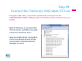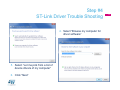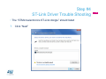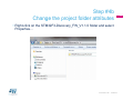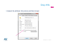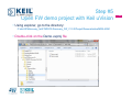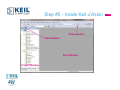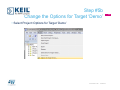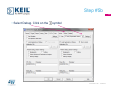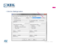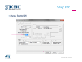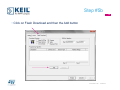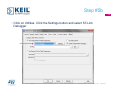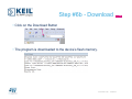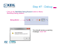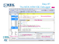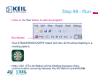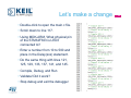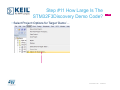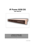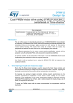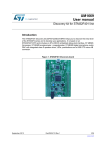
1
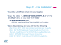
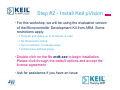
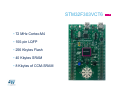
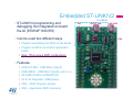
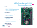
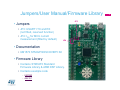
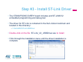
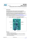
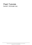
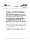
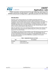
STM32F3
Hands-On Workshop
Welcome – Hands-On
• Ensure you picked-up
• USB Flash Drive with STM32F3 Discovery Kit Contents
• USB Cable
• STM32F3-Discovery Kit – will be provided after software is loaded
2
Keil uVision IDE Installation
Systems Check
• Everyone should have
• A Windows ® Laptop (XP, Vista, or Windows 7)
• USB Cable
• USB Flash Drive
• STM32F3-DISCOVERY kit: provided during the software installation.
• Ready to begin?
Note: please do not attempt to plug in the STM32F3-Discovery Kit into your laptop until instructed to do so.
4
Step #1 - File Installation
• Insert the USB Flash Drive into your Laptop
• Copy the folder “…\STM32F3DISCOVERY_Kit” on the
USB flash drive to your root “c:\” folder
• C:\STM32F3DISCOVERY_Kit\
• Edit folder properties and remove ‘Read-only’ attribute for all sub-folders.
• Open this directory and you will find the following:
• Keil µVision v4.71 Æ IDE tool installation application and license file.
• Docs ÆSTM32F3 Datasheets, Programming Manual, Reference
Manuals, Data Briefs, and The STM32F3 Discovery Board Manuals.
• Library Æ STM32F3Discovery Firmware Library folder.
• Utility Æ STM32F3 Clock Utility and ST-LINK Utility Application
5
Step #2 - Install Keil µVision
• For this workshop, we will be using the evaluation version
of the Microcontroller Development Kit from ARM. Some
restrictions apply:
• Program and debug up to 32 Kbytes of code
• No disassembly listing
• Some restriction on linkage usage
• Limited base address usage
• Double-click on the file mdk.exe to begin installation.
Please click-through the default options and accept the
license agreement
• Ask for assistance if you have an issue
6
Introducing the STM32F3Discovery Kit
STM32F303VCT6
• 72 MHz Cortex-M4
• 100-pin LQFP
• 256 Kbytes Flash
• 40 Kbytes SRAM
• 8 Kbytes of CCM-SRAM
STM32F303VCT6
8
Embedded ST-LINK/V2
• ST-LINK/V2 programming and
debugging tool integrated on-board
the kit (STM32F103C8T6)
• Can be used two different ways
ST-LINK/V2
CN3
USB ST-LINK
MCU
• Program and debug the MCU on the board
• Program an MCU on another application
board
• Note: JTAG versus SWD configuration.
STM32F303VCT6
• Features
• USB ST-LINK – USB Micro Type B
• USB USER – USB Micro Type B (USB FS,2.0)
• ST-LINK/V2 MCU (STM32F103)
• 5V to 3V Regulator (USB power)
• CN4 – MCU Program Jumper
• CN3 – Application SWD connector
9
USB USER
CN4
LEDs/Push-Buttons/MEMs/
Extension Connector
• LEDS
10
LD1 LD2
• LD1: Power indicator
• LD2: ST-LINK Communication indicator
• LD3 thru LD10: (PE8 thru PE15)
U3
• Push-Buttons
• B1: USER/Wake-up (PA0)
• B2: RESET (NRST)
• Extension Connector
P2
P1
• P1 and P2
• All GPIOs are available for prototype
U5
B1
B2
• Includes 5V, 3V and GND pins
• MEMs Devices
• U3: LSM303DLHC
• U5: L3GD20
LD3 thru LD10
Jumpers/User Manual/Firmware Library
JP3
• Jumpers
• JP3: USART1 TX and RX
(not fitted, reserved function)
• JP4: IDD for MCU current
measurement (fitted by default)
JP4
• Documentation
• UM1570 STM32F3DISCOVERY Kit
• Firmware Library
• Contains STM32F3 Standard
Firmware Library & ARM DSP Library.
• Contains example code
• UM1562
• AN4157
11
Step #3 - Install ST-Link Driver
• The STM32F3DISCOVERY board includes and ST-LINK/V2
embedded programming and debug tool
• The driver for ST-Link is contained in the Keil uVision toolchain and
located in this directory:
• C:\Keil\ARM\STLink\USBDriver
• Double-click on the file: ST-Link_V2_USBDriver.exe to install
• Click through the installation menu until the driver installation is
complete
12
Step #4:
Connect the Discovery Kit/Enable ST-Link
• Using the USB cable, connect the mini-B male connector into the
STM32F3DISCOVERY USB port and connect the A male connector into your
Laptop
• Wait for Windows to recognize the
ST-Link device and follow any step
required to install the driver
• Upon successful driver recognition,
the ST-Link device should be fully
enumerated in Windows Device
Manager as show:
13
Step #4
ST-Link Driver Trouble Shooting
1. Open Device Manager
2. Right-click on the STM32 ST-Link Driver icon
3. Select “Update Driver Software”
14
Step #4
ST-Link Driver Trouble Shooting
4. Select “Browse my computer for
driver software”
5. Select “Let me pick from a list of
device drivers of my computer”
6. Click “Next”
15
Step #4
ST-Link Driver Trouble Shooting
• The “STMicroelectronics ST-Link dongle” should listed
7. Click “Next”
16
Step #4
ST-Link Driver Trouble Shooting
• A warning message may appear
8. Select “Install this driver software anyway”
17
Step #4
ST-Link Driver Trouble Shooting
• You should receive a message:
“Windows has successfully updated
your driver software”
• Re-check device manager to ensure
STMicroelectronics ST-Link dongle
is functioning normally
18
STM32 F3 RESOURCES
Documentation resources
• All documentation can be found at www.st.com/stm32f3discovery
under the “Design support” tab and….
• In the directory C:\STM32F3Discovery_Kit\Docs
• You will find:
• STM32F30x Datasheet
• STM32F30x Reference Manual (RM0316)
• STM32F30x Cortex-M4 programming manual (PM0214)
• STM32F3DISCOVERY peripheral firmware examples (AN4157)
• Getting started with software and firmware environments for the
STM32F3DISCOVERY kit (UM1562)
• STM32F3DISCOVERY kit data brief (DB1739)
• STM32F3DISCOVERY kit user manual (UM1570)
• Evaluation Product License Agreement
20
Documentation resources
• Main website page for the STM32 family
• www.st.com/stm32
• For STM32F3
• www.st.com/stm32f3
• You can find
• Datasheets
• Applications Notes
• Errata
• Technical Notes
• Programming Manuals
• Reference Manual
• User Manuals
• Firmware
21
Support resources
• Technically trained distributors
• Distributors listed on CONTACTS page, www.st.com/contactus
• ST Public Forums:
• Located on main
www.st.com page under
Support tab – ST e2e
Communities
• Submit technical
questions to ST Online
Support:
• Located on main
www.st.com page under the
Support tab – Online
Support
22
Process check
23
LD1 LD2
• At this point the ST-Link V2 should be recognized
by your system.
LD4
• LD1 and LD2 should be on ON (indicating the
board is powered and ST-Link is functional).
• LD3 to LD10 will be flashing in a rotating pattern.
• Board Test:
• Press the USER Button Once to Select Gyro Function
• LD6 & LD9 (Green) will light when the Discovery board is rotated along the Roll access.
• LD4 & LD10 (Blue) will light when the Discovery board is rotated along the Pitch access.
• Press the USER Button a 2nd time to Select the Digital Compass Function.
• LD3 thru LD10 will Flash randomly until the Discovery is rotated.
• Rotate the Discovery board around the Yaw axis until LD4 (Blue) lights. LD4 will be pointing
to magnetic North. (The STLINK USB connector will be pointing to the South.)
• Rotate the Discovery Board around the Pitch or Roll axis.
Hands-On Part I:
Edit, Compile, Download, Debug, and Run
Step #4b
Change the project folder attributes
• Right-click on the STM32F3-Discovery_FW_V1.1.0 folder and select
Properties…
Presentation Title
13/08/2013
25
Step #4b
26
• Unselect the attribute: Only lecture and then Accept
Presentation Title
13/08/2013
Step #5
Open FW demo project with Keil uVision
• Using explorer, go to the directory:
C:\stm32f3discovery_fw\STM32F3-Discovery_FW_V1.0.0\Project\Demonstration\MDK-ARM
• Double-click on the Demo.uvproj file
27
Step #5 - Inside Keil uVision
Debug Button
Build Button
Files Window
Project Window
28
Step #5b
Change the Options for Target ‘Demo’
• Select Project::Options for Target ‘Demo’
Presentation Title
13/08/2013
29
Step #5b
30
• Select Debug. Click on the
symbol
Presentation Title
13/08/2013
Step #5b
31
• Select ST-Link Debugger
Presentation Title
13/08/2013
32
• Click the Settings button
Presentation Title
13/08/2013
Step #5b
33
• Change Port to SW
Presentation Title
13/08/2013
Step #5b
34
• Click on Flash Download and then the Add button
Presentation Title
13/08/2013
Step #5b
35
• Select STM32F3xx Flash and then click on the Add button
Presentation Title
13/08/2013
Step #5b
36
• Click on Utilities. Click the Settings button and select ST-Link
Debugger
Presentation Title
13/08/2013
Step #5b
37
• Finally, click on OK
Presentation Title
13/08/2013
Step #6 - Compile
• Click on the Build button or Menu::Project::Build Target
Build Button
• The project should compile without errors
38
Step #6b - Download
• Click on the Download Button
• The program is downloaded to the device’s flash memory.
Presentation Title
13/08/2013
39
Step #7 - Debug
• Click on the Start/Stop Debug Session button or Menu:
Start/Stop Debug Session
Debug Button
• You should receive a warning
message. Click “OK”
40
Step #7:
The MDK-ARM IDE Debugger
Disassembly Window
Files Window
Program counter position
Command Window
Register Window
Memory Windows
41
Step #8 - Run
• Click on the Run button to start the program
Run Button
• Your STM32F3DISCOVERY board LD3 thru LD10 will be flashing in a
rotating pattern.
• Note: LD2 (ST-Link Status) will be flashing because of the
communication occurring between the STLINK/V2 and EWARM.
42
Step #8 - Run
• Mission Accomplished
• Please click on the Stop
button.
• You code will stop
anywhere within the
program flow
Stop Button
• Click on the Debug button
to exit from the debugger
Debug Button
43
Let’s make a change
• Double-click to open the main.c file.
• Scroll down to line 117.
• Using MDK-ARM, What physical pin
of the STM32F303 is LED3
connected to?
• Enter a number from 10 to 500 and
place in the Delay(xxx) statement.
• Do the same thing with lines 121,
125, 129, 133, 137, 141, and 145.
• Compile, Debug, and Run
• Validate! Did it work?
• Stop debug and exit the debugger
44
Step #10 Let’s take a look and
make a change
45
Step #11 How Large Is The
STM32F3Discovery Demo Code?
• Select Project::Options for Target ‘Demo’…
Presentation Title
13/08/2013
46
Step #11 How Large Is The
STM32F3Discovery Demo Code?
• Select Listing. Then select Linker Listing. Finally click on the OK
button.
Presentation Title
13/08/2013
47
Step #11 How Large Is The
STM32F3Discovery Demo Code?
• Click on Æ Project Æ Build, to re-link the project and generate the
‘Demo.map’.
• Edit the ‘Demo.map’ file.
• How much STM32F3 FLASH is required?
• How much STM32F3 SRAM is required?
Presentation Title
13/08/2013
48
STM32F3-Discovery Demo
Firmware Project Overview
Project Files
• MDK-ARM
• startup_stm32f30x.s
• System initialization, vector table, reset and branch to main()
(Unique for each 3rd party tool chain)
• STM32_USB-FS-Device_Driver
• Contains ST FS USB library functions.
• ST,3F3-Discovery
• Board specific functions
• STM32F30x_StdPeriph_Driver
• Contains peripheral library functions
• User files
• main.c (program entry point)
• system_stm32f3xx.c (initial system configuration)
• stm32f0xx_it.c (ISR’s)
• usb_xxxx.c (USB interface, not used)
50
startup_stm32f30x.s
• Main Characteristics
• Initializes stack pointer
• Contains the vector table for the part
• Contains Reset handler –
called on system reset
• Calls SystemInit() function
• Branches to main()
51
system_stm32f30x.c
• SystemInit()
• This function is called at startup just after reset and before branch to main program.
This call is made inside the "startup_stm32f3xx.s" file.
• Setups the system clock (System clock source, PLL Multiplier and Divider factors, AHB/APBx
prescalers and Flash settings) Æ STM32F3 Clock Configuration Tool
Define PLL source
SystemInit()
.
.
.
Call SetSysClock()
52
main.c
• Example main()
• Standard C main() function entry
• Start of application program
• What happens each time the USER
Button is pushed?
•
•
•
•
Goto Line 99, while(1)
Goto Line 112, LD3-LD10Æ Pattern
Goto Line 164, LD3-LD10Æ Gyro
Goto Line 232, LD3-LD10Æ Compass
53
stm32f30x_it.c
• Contains Cortex-M4 Processor Exception Handlers (ISRs)
• void NMI_Handler(void);
• void HardFault_Handler(void);
• void SVC_Handler(void);
• void PendSV_Handler(void);
• void SysTick_Handler(void);
• Contains the STM32F30x Peripherals Interrupt Handlers (default is
empty)
• Add the Interrupt Handler for the used peripheral(s) (PPP), for the available
peripheral interrupt handler's name please refer to the startup file:
startup_stm32f30x.s
• Go to Line 148: SysTick_Handler
• What is SysTick ISR being used for?
• Go to Line 166: EXTI0_IRQHandler
• What is the ISR use?
• What physical pin of the STM32F3 is the ‘User Button’ connected to?
54
STM32F3-discovery.c
• Contains board specific function and definition
• Defines Push-button and LED GPIO definitions
• Contains board specific functions
• void STM_EVAL_LEDInit(Led_TypeDef Led);
• void STM_EVAL_LEDOn(Led_TypeDef Led);
• void STM_EVAL_LEDOff(Led_TypeDef Led);
• void STM_EVAL_LEDToggle(Led_TypeDef Led);
• void STM_EVAL_PBInit(Button_TypeDef Button,
ButtonMode_TypeDef Button_Mode);
• uint32_t STM_EVAL_PBGetState(Button_TypeDef Button);
55
stm32f30-discovery_l3gd20.c
stm32f3-discovery_lsm303dlhc.c
• Each contains the driver information for the MEMs devices on
STM32F3-Discovery Board.
• Each contains board specific functions
56
STM32F30x_StdPeriph_Driver
• Each file contains library functions that can be
used for each peripheral and gives a standard
API for access to peripheral functions.
• Browse to Æ main.c, line 83, STM_EVAL_LEDInit(LED5),
to investigate GPIO config.
• Browse to Æmain.c, line 161, Demo_GyroConfig(), to
investigate the Gryo config and the I2C config.
57
Thank you
www.st.com/stm32f3discovery