1
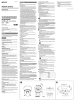
4-450-485-11 (1) Network Camera Für Kunden in Europa, Australien und Neuseeland White flecks WARNUNG Although the image sensors are produced with high-precision technologies, fine white flecks may be generated on the screen in rare cases, caused by cosmic rays, etc. This is related to the principle of image sensors and is not a malfunction. The white flecks especially tend to be seen in the following cases: - when operating at a high environmental temperature - when you have raised the gain (sensitivity) - when using the slow shutter Dies ist eine Einrichtung, welche die Funk-Entstörung nach Klasse A besitzt. Diese Einrichtung kann im Wohnbereich Funkstörungen verursachen; in diesem Fall kann vom Betreiber verlangt werden, angemessene Maßnahmen durchzuführen und dafür aufzukommen. Sollten Funkstörungen auftreten, wenden Sie sich bitte an den nächsten autorisierten Sony-Kundendienst. This apparatus shall not be used in the residential area. Ne pas utiliser cet appareil dans une zone résidentielle. Dieser Apparat darf nicht im Wohnbereich verwendet werden. Installation Manual ATTENTION Before operating the unit, please read this manual thoroughly and retain it for future reference. The electromagnetic fields at the specific frequencies may influence the picture of this unit. Notes on Use 2012 Sony Corporation Printed in China Owner’s Record Refer to these numbers whenever you call upon your Sony dealer regarding this product. Model No. Serial No. WARNING To avoid electrical shock, do not open the cabinet. Refer servicing to qualified personnel only. Afin d’écarter tout risque d’électrocution, garder le coffret fermé. Ne confier l’entretien de l’appareil qu’à un personnel qualifié. Um einen elektrischen Schlag zu vermeiden, darf das Gehäuse nicht geöffnet werden. Überlassen Sie Wartungsarbeiten stets nur qualifiziertem Fachpersonal. CAUTION This installation should be made by a qualified service person and should conform to all local codes. CAUTION The rating label is located underneath the top unit. ATTENTION L’étiquette de régime nominal est située sous l’unité supérieure. VORSICHT Das Typenschild befindet sich unterhalb der oberen Einheit. Power Supply Caution for U.S.A. and Canada The SNC-ER585/ER585H operates on 24 V AC. In the USA, these products shall be powered by a UL listed Class 2 Power supply Only. In Canada, these products shall be powered by a CSA Certified Class 2 Power Supply Only. Caution for other countries The SNC-ER585/ER585H operates on 24 V AC. Use a power supply rated 24 V AC which meets the requirements for SELV (Safety Extra Low Voltage) and complies with Limited Power Source according to IEC 60950-1 second edition. Alimentation Avertissement pour les États-Unis et le Canada La caméra SNC-ER585/ER585H fonctionne sous 24 V c.a. Aux États-Unis, ce produit doit être utilisé uniquement avec une source d’alimentation de classe 2 répertoriée dans la liste UL. Au Canada, ce produit doit être utilisé uniquement avec une source d’alimentation de classe 2 certifiée CSA. Avertissement pour les autres pays La caméra SNC-ER585/ER585H fonctionne sous 24 V c.a. Utilisez une source d’alimentation de 24 V c.a. TBTS (Très basse tension de sécurité) conforme aux dispositions de la section Sources à puissance limitée de la norme CEI 60950-1, deuxième édition. For the customers in the U.S.A. This device complies with Part 15 of the FCC Rules. Operation is subject to the following two conditions: (1) this device may not cause harmful interference, and (2) this device must accept any interference received, including interference that may cause undesired operation. NOTE: This equipment has been tested and found to comply with the limits for a Class A digital device, pursuant to Part 15 of the FCC Rules. These limits are designed to provide reasonable protection against harmful interference when the equipment is operated in a commercial environment. This equipment generates, uses, and can radiate radio frequency energy and, if not installed and used in accordance with the instruction manual, may cause harmful interference to radio communications. Operation of this equipment in a residential area is likely to cause harmful interference in which case the user will be required to correct the interference at his own expense. You are cautioned that any changes or modifications not expressly approved in this manual could void your authority to operate this equipment. All interface cables used to connect peripherals must be shielded in order to comply with the limits for a digital device pursuant to Subpart B of Part 15 of FCC Rules. For the customers in Canada This Class A digital apparatus complies with Canadian ICES-003. Cet appareil numérique de la classe A est conforme à la norme NMB-003 du Canada. For the customers in Europe The manufacturer of this product is Sony Corporation, 1-7-1 Konan, Minatoku, Tokyo, 108-0075 Japan. The Authorized Representative for EMC and product safety is Sony Deutschland GmbH, Hedelfinger Strasse 61, 70327 Stuttgart, Germany. For any service or guarantee matters please refer to the addresses given in separate service or guarantee documents. Pour les clients en Europe Le fabricant de ce produit est Sony Corporation, 1-7-1 Konan, Minato-ku, Tokyo, 108-0075 Japon. Le représentant autorisé pour EMC et la sécurité des produits est Sony Deutschland GmbH, Hedelfinger Strasse 61, 70327 Stuttgart, Allemagne. Pour toute question concernant le service ou la garantie, veuillez consulter les adresses indiquées dans les documents de service ou de garantie séparés. Für Kunden in Europa Der Hersteller dieses Produkts ist Sony Corporation, 1-7-1 Konan, Minato-ku, Tokyo, 108-0075 Japan. Der autorisierte Repräsentant für EMV und Produktsicherheit ist Sony Deutschland GmbH, Hedelfinger Strasse 61, 70327 Stuttgart, Deutschland. Bei jeglichen Angelegenheiten in Bezug auf Kundendienst oder Garantie wenden Sie sich bitte an die in den separaten Kundendienst- oder Garantiedokumenten aufgeführten Anschriften. For the customers in Europe, Australia and New Zealand WARNING This is a Class A product. In a domestic environment, this product may cause radio interference in which case the user may be required to take adequate measures. In the case that interference should occur, consult your nearest authorized Sony service facility. Pour les clients en Europe, Australie et Nouvelle-Zélande AVERTISSEMENT Il s’agit d’un produit de Classe A. Dans un environnement domestique, cet appareil peut provoquer des interférences radio, dans ce cas l’utilisateur peut être amené à prendre des mesures appropriées. Si des interférences se produisent, contactez votre service après-vente agréé Sony. When fine patterns, stripes, or lines are shot, they may appear jagged or flicker. About the Supplied Manuals Installation Manual (this document) Before Use This Installation Manual describes the names and functions of parts and controls of the Network Camera, gives connection examples and explains how to set up the camera. Be sure to read the Installation Manual before operating. If you find condensation when you open the package, turn on the power after the condensation disappears. User’s Guide (stored in the CD-ROM) Data and security SNC-ER585/ER585H Aliasing Since the service is Internet-based, there is a risk that the image or audio you are monitoring can be viewed or used by a third-party via the network. You should keep in mind that the images or audio you are monitoring may be protected by privacy and other legal rights, and the responsibility for making sure you are complying with applicable laws is yours alone. Access to the images and audio is protected only by a user name and the password you set up. No further authentication is provided nor should you presume that any other protective filtering is done by the service. SONY IS NOT RESPONSIBLE, AND ASSUMES ABSOLUTELY NO LIABILITY TO YOU OR ANYONE ELSE, FOR SERVICE INTERRUPTIONS OR DISCONTINUATIONS OR EVEN SERVICE CANCELLATION. THE SERVICE IS PROVIDED AS-IS, AND SONY DISCLAIMS AND EXCLUDES ALL WARRANTIES, EXPRESS OR IMPLIED, WITH RESPECT TO THE SERVICE INCLUDING, BUT NOT LIMITED TO, ANY OR ALL IMPLIED WARRANTIES OF MERCHANTABILITY, FITNESS FOR A PARTICULAR PURPOSE, OR THAT IT WILL OPERATE ERROR-FREE OR CONTINUOUSLY. Security configuration is essential for wireless LAN. Should a problem occur without setting security, or due to the limitation of the wireless LAN specifications, SONY shall not be liable for any damage, loss of recorded data or restoration thereof. Always make a test recording, and verify that it was recorded successfully. SONY WILL NOT BE LIABLE FOR DAMAGES OF ANY KIND INCLUDING, BUT NOT LIMITED TO, COMPENSATION OR REIMBURSEMENT ON ACCOUNT OF FAILURE OF THIS UNIT OR ITS RECORDING MEDIA, EXTERNAL STORAGE SYSTEMS OR ANY OTHER MEDIA OR STORAGE SYSTEMS TO RECORD CONTENT OF ANY TYPE. Always verify that the unit is operating properly before use. SONY WILL NOT BE LIABLE FOR DAMAGES OF ANY KIND INCLUDING, BUT NOT LIMITED TO, COMPENSATION OR REIMBURSEMENT ON ACCOUNT OF THE LOSS OF PRESENT OR PROSPECTIVE PROFITS DUE TO FAILURE OF THIS UNIT, EITHER DURING THE WARRANTY PERIOD OR AFTER EXPIRATION OF THE WARRANTY, OR FOR ANY OTHER REASON WHATSOEVER. If you lose data by using this unit, SONY accepts no responsibility for restoration of the data. Personal information The images taken by the system using this device can identify individuals and thus they fall under “personal information” stipulated in the “Act on the Protection of Personal Information”. Please handle the video data appropriately according to law. Information recorded using this product may also be “personal information”. Upon disposal, transfer, repair, or any other occasion where this product or storage media is passed on to a third party, practice due care in its handling. Operating or storage location Avoid operating or storing the camera in the following locations. Extremely hot or cold places Close to sources of strong magnetism Close to sources of powerful electromagnetic radiation, such as radios or TV transmitters Locations subject to vibration or shock Locations where radiation or X-rays are emitted Near the outdoor unit of an air conditioner or any other place where drastic temperature changes may occur (this may cause clouding of the dome cover) Locations subject to steam or high humidity Locations subject to strong wind, such as high places Locations where corrosive gas or flammable gas is emitted, or where salt damage may occur Ventilation The User’s Guide describes how to set up the camera and how to control the camera via a Web browser. After installing and connecting the camera correctly, operate referring to this User’s Guide. Using the CD-ROM manual The manual can be read on a computer with Adobe Reader installed. You can download Adobe Reader free from the Adobe website. 1 Open the index.htm file in the CD-ROM. 2 Select and click on the manual that you want to read. Note If you have lost or damaged the CD-ROM, you can purchase a new one from your Sony dealer or Sony service counter. Adobe and Acrobat Reader are trademarks of Adobe Systems Incorporated in the United States and/or other countries. Location and Function of Part Camera (Front) Top sunshade Sunshade Dome cover Top Unit (Bottom) Reset switch This switch returns the setting of the device to the factory default setting. 1. Move the INIT switch in the direction indicated by and connect with camera. 2. Turn on power and wait 1 minute. After the initialization is completed, the camera starts. 3. Check that the camera has started and turn off the power to remove camera. 4. Move the INIT switch back to its original position. Notes Resetting the device removes all customized settings. It is recommended that users save the settings as necessary. Instructions on how to save settings are available in the User’s Guide. The reset switch should always be returned to its original position. Otherwise your device is reset to its factory default setting whenever it is turned on. Camera connection terminal Connect to the camera connection terminal of the camera. AC 24 V (power input) terminal Use the supplied AC connector to connect to the 24 V AC power supply system. Pin No. Always turn off the power when carrying. When transporting the camera, repack it as originally packed at the factory or in materials of equal quality. Pin name 1 AC 24 V+ 2 Frame Ground 3 AC 24 V– I/O (Input/Output) port Provides two sensor inputs and one alarm outputs. Connect the supplied I/O harness. Pin No. Pin name Color Pin No. Pin name Color 1 Alarm Out 1– Blue 8 NC Yellow 2 Alarm Out 1+ Blue 9 NC Orange Humidity when installing the device 3 NC Yellow 10 NC Red Install this device under low humidity condition. Otherwise the dome cover may cloud up during operation. 4 NC Orange 11 NC Brown 5 Sensor In 2 Red 12 GND Black Using in cold climates (SNC-ER585 only) 6 Sensor In 1 Brown 13 NC Purple 7 GND Black 14 NC Purple Installation Ensure that the dome cover is installed facing perpendicularly downward without any tilt. This device is equipped with a built-in heater, which automatically turns on if the internal temperature is significantly low. Note that, in some environments, the heater may not melt snow or frost on the dome cover. Starting and closing under low temperature When starting the SNC-ER585 in temperatures below 0 °C (32 °F), the camera system may not start operating immediately after start-up. In such a case, the heater starts and raises the internal temperature, starting the camera system. It may take about two hours for the camera system to start streaming normal images. Since there is no heater function in the SNC-ER585H, it cannot be started in temperatures below 0 °C (32 °F). If the unit is turned off in an ambient temperature of 0 °C (32 °F) or below, condensation may occur in the dome cover, which may take some time to clear after turning the unit on again. In order to prevent the prolonged condensation, it is recommended that to leave this unit powered on for a short term recess, in that environment. Cleaning Use a soft, dry cloth to clean the external surfaces of the camera. Stubborn stains can be removed using a soft cloth dampened with a small quantity of detergent solution, then wipe dry. Do not use volatile solvents such as alcohol, benzene or thinners as they may damage the surface finishes. Please consult the store of purchase or authorized Sony dealer if there were troubles and anomalies. (continued on the reverse side) The CD-ROM supplied with this product includes the User’s Guide (in PDF format) and a setup program for assigning an IP address. This product is equipped with a Smartphone viewer. For more details, see “Smartphone viewer User’s Manual” at the following URL: http://www.sony.net/ipela/snc Transportation Always connect the ground cable before connecting the power cable to the main power supply. Before removing the ground connection, disconnect the power cable from the main power supply. This unit should be always connected to the ground connection to reduce damage from lightning strike, etc. Check that the ground cable is correctly and securely connected before use. Note For information about Sony-approved SD memory cards, contact your Sony dealer. Using the software To prevent heat buildup, do not block air circulation around the camera. Grounding Camera (Top) Camera connection terminal Connect to the camera connection terminal of the top unit. Rating Label This label shows the name of device and its electric rating. Built-in wire rope The wire rope is used for fall-prevention. SD memory card slot This slot is used for an optional SD memory card. Images captured by the camera can be stored into an inserted memory card. Be sure that the printed side of a memory card and the product specifications label face in the same direction, and then insert the card firmly into the slot. (a) This unit only supports memory card formats compatible with the SD/SDHC standards. LAN (network) port (RJ-45) Connect to a 10BASE-T or 100BASE-TX network using a network cable (UTP, category 5). CAUTION For safety, do not connect the connector for peripheral device wiring that might have excessive voltage to this port. Follow the instructions for this port. ATTENTION Par mesure de sécurité, ne raccordez pas le connecteur pour le câblage de périphériques pouvant avoir une tension excessive à ce port. Suivez les instructions pour ce port. VORSICHT Aus Sicherheitsgründen nicht mit einem Peripheriegerät-Anschluss verbinden, der zu starke Spannung für diese Buchse haben könnte. Folgen Sie den Anweisungen für diese Buchse. Harness holder Attach the supplied band mount. (microphone input) terminal (minijack, monaural) Connect a commercially available microphone. (line output) terminal (minijack, monaural) Connect to a commercially available speaker with a built-in amplifier. Note on laser beams Laser beams may damage image sensors. You are cautioned that the surface of image sensors should not be exposed to laser beam radiation in an environment where a laser beam device is used. About the SD Memory Card Data on the SD Memory Card may be damaged or deleted in the following cases. Sony is not responsible for compensation for damage or lost earnings due to damage or loss of data. If you remove the SD Memory Card from this device or turn off the power while the SD Memory Card is being accessed. If the SD Memory Card is subject to shock. When the lifetime of the SD Memory Card expires. (Lifetime may shorten significantly, depending on its use.) If the SD Memory Card is not set or inserted properly. Camera settings DynaView(WDR) is not available when the slow shutter is used. The exposure compensation function is not available when DynaView(WDR) is used. Phenomena Specific to Image Sensors The following phenomena that may occur in images are specific to image sensors. They do not indicate a malfunction. a Printed side How to install the camera Installation 1 b Notes Do not allow water to come in contact with the power cable, connection cables or connectors, as it may cause water leakage into this device, and subsequent damage. The mounting arm (not supplied) to which the device is attached should have fixing screws of NPT 1 1/2” specified by a Sony dealer. Using an unspecified mounting arm may cause water leakage into this device, and subsequent damage. Be sure to use the specified mounting arm. The lens zoom and angle may result in a blurred or inclined image within the range above the horizon of the lens position. To prevent the dome cover from damage and stain, do not remove the protecting sheet from the dome cover until the setting is completed. Dome cover a Note Always connect pin 2 (center) to the ground terminal. Screws (6) O-ring Warning If installing the camera in high location, such as high wall, entrust the installation to a professional contractor or service personnel. The camera should be securely installed on a location strong enough to support the weight of the camera and the mounting arm. Otherwise, the camera and mounting arm may fall and cause serious injury. For the fall-prevention of the camera, make sure to use the wire rope. If the bolts are attached loosely or loosen, the camera and parts may fall. There may also be a risk of water leakage. Make sure to tighten the bolts and screws so that they will not loosen. Check the camera is attached securely, the screws, etc. are not loosened periodically, at the least once a year. Depending on the usage conditions, periodic inspections should be conducted more frequently. Band mount Camera 100 mm to 125 mm (4 inches to 5 inches) b Harness band Cable 8 Recommended power cable 24 V AC Cable(AWG) #22 #20 #18 #16 Maximum cable length (m (feet)) 5 (16.4) 8 (26.2) 15 (49.2) 21 (68.9) Connecting the I/O Cable Wiring diagram for sensor input Mechanical switch/open collector output device Camera inside 10 kohms 2.2 kohms 10 kohms Use the supplied screws to install the unit. Using other screws may cause damage inside the unit. How to Install GND GND Mechanical switch GND 7 or 12 pin GND Camera inside Referring to the installation manual of the mounting arm (not supplied), drill the required holes for the mounting screws and the connection cable. Then install the mount arm in advance. After that, wrap the screw part of the mounting arm in a shield tape (not supplied). Outside R 1 Attach the dome cover to the camera. (a) Tighten the six screws in the specified order (1 to 6). (b) Mounting arm (not supplied) Keep parallel Bolts Wire bracket 2 pin (Alarm Output +) Notes c Wire-fixing belt Shield tape (not supplied) Cable Nuts Remove the drafting tape from the O-ring before attaching the dome cover. Be sure to properly place the O-ring in the groove firmly before attaching the dome cover. If the O-ring is not properly and firmly placed, waterproof performance may be compromised. The six screws should be tightened to 1.2 N•m. 2 Attach the supplied wire-fixing belt and wire bracket to the mounting arm (not supplied). Then secure the wire-fixing belt and wire bracket to the mounting arm by tightening two nuts. Note The two bolts should be tightened to 5.2 N•m. 3 Screw the supplied coupling on the mounting arm. Note Coupling If the coupling is attached loosely or loosens, the camera may fall. Securely put the coupling around the mounting arm so that it will not loosen. 9, 10 4 Fallprevention wire Locking screws (2) Bolts (3) 4 Remove the three bolts from the top part of the camera, and turn the top unit until it stops, then pull it upward to remove it from the camera. Have a 5 mm (7/32 inch) hex wrench ready to loosen the bolts. 5 Attach the top unit to the mounting arm. Place the locking screws fixed to the top unit in the groove of the coupling and turn the top unit until it stops, in the direction of the arrow. Top unit Align the triangular and square marks Top unit Camera Notes Remove the drafting tape from the waterproof seal before attaching the mounting arm. Be sure to verify that the locking screws are not loose. If the locking screws are loose, the camera may fall. The locking screws should be tightened to 5.2 N•m. Be sure to tighten the waterproof seal properly to the top unit before attaching; otherwise, waterproof performance may be compromised. 6 Attach the two supplied bolts to the screw holes of the coupling and tighten them. O-ring 5 Note The two bolts should be tightened to 5.2 N•m. 11 7 Run the supplied harness band through the band-mounting hole (a), tie the cables at 100 mm to 125 mm (4 inches to 5 inches) from the cable head (b). If the tied position is not appropriate, push the release button of the harness band to loosen, and tie the cables again. 8 Secure the band mount to the harness holder (a), and connect the cables. Push the cables into the top unit (b). Be sure that all cable connection sides of the top unit are in parallel with the harness holder. (c) 9 Hook the fall-prevention wire of the camera on the hole of the wire bracket. 10Align the triangular mark of the camera and square mark of the top unit and push the camera into the top unit. Then turn the camera until it stops, in the direction of the arrow. Bolts (3) Top unit Waterproof seal Notes Camera Locking screws (2) 12 Be sure to properly place the O-ring in the groove firmly before attaching the camera. If the O-ring is not properly and firmly placed, waterproof performance may be compromised. Be sure that the camera connection terminal of the top unit is in parallel with the harness holder before pushing the camera into the top unit. To prevent the cables from getting caught, push the slack part of the cables into the top unit before attaching the camera. Top sunshades Top unit 6 11Attach the camera to the top unit using the three bolts which were removed Bolts (2) in step 4. Note The three bolts should be tightened to 5.2 N•m. 12Separate the provided top sunshade and reattach the separated parts above the camera to return the top sunshade to its original form. Notes Run the fall-prevention wire through the top sunshade. Securely attach the top sunshade so that the snap hook will not get caught in it. 13, 14 Screw Top sunshade Top unit 7 Align the triangular marks 13Align the respective triangular marks of the camera and top sunshade and push the top sunshade into the camera. Then turn the sunshade until it stops, in the direction of the arrow. 14Secure the camera and top sunshade using the screw on the top sunshade. Notes a Please make sure to attach the top sunshade. The top sunshade prevents the device from overheating in direct sunlight. The screw should be tightened to 1.2 N•m. Harness band Removing the camera 1 Remove the one screw that secures the top sunshade to the camera in Step 14 of “How to install the camera” to remove the top sunshade. 2 Remove the three bolts used in Step 11 of “How to install the camera.” 3 Turn the top unit to the position where the triangular mark of the camera and Release button the square mark of the top unit align, and pull the camera out downwards. 4 Remove the fall-prevention wire of the camera from the hole of the wire bracket. Connection Connecting to the Network Connect the LAN port of the camera unit to a router or hub in the network using the network cable (not supplied). Connecting the Power Source 324.1 (12 7/8) Harness mount Open collector output device 24 V DC How to install the camera 2, 3 or Wiring diagram for alarm output Before installation b 5 or 6 pin (Sensor Input 1 or 2) 10 kohms Note a Outside 3.3 V Always have the stopper side face down and tie the cables. The following method is available for connecting to a power source. 24 V AC Connecting to a 24 V AC power source supply Connect the 24 V AC power supply system to the power input terminal of the camera. The AC power cable is not supplied. Use a 24 V AC power source isolated commercial power supply. The usable voltage range is as follows: 24 V AC: 21.6 to 26.4 V Use a UL cable (VW-1 style 10368) for 24 V AC connection. ø222 (8 3/4) Unit: mm (inches) Magnet relay 24 V AC 24 V DC, 1 A or less Circuit example 1 pin (Alarm Output –) GND Specifications Compression Video compression format Audio compression format Maximum frame rate JPEG/MPEG4/H.264 G.711/G.726 (40,32,24,16 kbps) 30 fps Camera Image device1/2.8 type Exmor CMOS SynchronisingInternal Minimum illumination1.7 lx (Shutter speed: 1/30 sec, Exposure: Full auto, 50IRE [IP]) Video S/N 50 dB (Gain 0 dB) Lens Focus length Maximum relative aperture Minimum object distance f=4.3 mm to 129.0 mm F1.6 to F4.7 300 mm Mechanism Pan Tilt 360°, endless rotation Maximum speed: 300°/s 210° (with auto invert function) Maximum speed: 300°/s Interface LAN10BASE-T/100BASE-TX, auto negotiation (RJ-45) I/O Input/Output Sensor input: × 2, make contact Alarm output: × 1, 24 V AC/DC, 1 A (mechanical relay outputs electrically isolated from the camera) SD memory card slot Microphone input Minijack (monaural) Plug-in-power supported (rated voltage: 2.5 V DC) Recommended load impedance 2.2 kohms Line output Minijack (monaural), Maximum output level: 1 Vrms Others Power supply 24 V AC ± 10%, 50 Hz/60 Hz Power consumption SNC-ER585 Max. 76 W SNC-ER585H Max. 26 W Operating temperature SNC-ER585 –40 °C to +60 °C (–40 °F to 140 °F) Activation temperature range: –40 °C to +60 °C (–40 °F to 140 °F) SNC-ER585H Maximum temperature range: –5 °C to +65 °C (23 °F to 149 °F) (2 hours use) Continuous use temperature range: –5 °C to +60 °C (23 °F to 140 °F) Activation temperature range: 0 °C to +65 °C (32 °F to 149 °F) Storage temperature –20 °C to +60 °C (–4 °F to +140 °F) Operating humidity 20% to 80% Storage humidity 20% to 95% Dimensions (Diameter/Height) ø222 mm × 324.1 mm (ø8 3/4 inches × 12 7/8 inches) (Not including the projecting parts) Mass Approx. 4.3 kg (9 lb 8 oz) Supplied accessories Dome cover (1) Top sunshade (1) Coupling (1) Wire-fixing belt (1) Wire bracket (1) Bolts (2) Power supply connector 3-pin (1) I/O harness 14-pin (1) Harness band (1) Band mount (1) Installation manual (1 set) CD-ROM (User’s Guide, supplied programs) (1) Design and specifications are subject to change without notice. Recommendation of Periodic Inspections In case using this device over an extended period of time, please have it inspected periodically for safe use. It may appear flawless, but the components may have deteriorated over time, which may cause a malfunction or accident. For details, please consult the store of purchase or an authorized Sony dealer.