1
MODBUS
COMMUNICATIONS
CHAPTER
6
In This Chapter ...
SureServo™ Communication Parameters . . . . . . . .6–2
SureServo™ Parameter Memory Addresses . . . . . .6–3
Connecting to DirectLogic PLCs . . . . . . . . . . . . . . .6–8
Step 1: Modbus RTU Master PLCs . . . . . . . . . . . . . . . . . . . . . . .6–8
Step 2: Make the Connections . . . . . . . . . . . . . . . . . . . . . . . . . .6–8
Step 3: Confirm/Set Servo Communication Parameters . . . . . .6–10
Step 4: Configure the DirectLOGIC CPU Port 2 . . . . . . . . . . . . .6–10
SureServo™ / DirectLOGIC PLC Control Example .6–13
DirectLOGIC Ladder Programming Example – Multiple Drives . .6–22
Communicating with Third-party Devices . . . . . .6–24
Common Modbus RTU Masters . . . . . . . . . . . . . . . . . . . . . . . .6–24
Modbus Protocol Modes . . . . . . . . . . . . . . . . . . . . . . . . . . . . . .6–25
Modbus ASCII and RTU Data Format . . . . . . . . . . . . . . . . . . . .6–25
Communication Protocol . . . . . . . . . . . . . . . . . . . . . . . . . . . . .6–27
Chapter 6: Modbus Communications
SureServo™ Communication Parameters
The SureServo™ drives support the Modbus RTU/ASCII communications protocols
as a slave device only. Drive serial port CN3 can be connected to a Modbus
master using RS-232, RS-422 or RS-485 communications (port pin-outs and wiring
diagrams are shown later in this chapter). This chapter lists all of the drive’s
parameters along with the corresponding Modbus addresses. Network masters,
such as DirectLogic PLCs, can be used to read/write drive(s) parameters.
The SureServo drive Communications Parameters listed below must be set using the
SureServo Pro software or the drive keypad unless the defaults are appropriate for your
application. For a detailed explanation of all SureServo Parameters, refer to CHAPTER 4.
Communications Parameters
Parameter Description
Range
P3-00
Communication Address
01 to 254
01
Transmission Speed
00: 4800 baud
01: 9600 baud
02: 19200 baud
03: 38400 baud
04: 57600 baud
05: 115200 baud
02
P3-02
Communication Protocol
00: Modbus ASCII mode
7 data bits, no parity, 2 stop bits
01: Modbus ASCII mode
7 data bits, even parity, 1 stop bit
02: Modbus ASCII mode
7 data bits, odd parity, 1 stop bit
03: Modbus ASCII mode
8 data bits, no parity, 2 stop bits
04: Modbus ASCII mode
8 data bits, even parity, 1 stop bit
05: Modbus ASCII mode
8 data bits, odd parity, 1 stop bit
06: Modbus RTU mode
8 data bits, no parity, 2 stop bits
07: Modbus RTU mode
8 data bits, even parity, 1 stop bit
08: Modbus RTU mode
8 data bits, odd parity, 1 stop bit
08
P3-03
Transmission Fault Action
00: Display fault and continue operating
01: Display fault and RAMP to stop
00
P3-04
Communication Watchdog
Time Out
0 to 20.0 seconds
00
P3-05
Communication Selection
00: RS-232
01: RS-422
02: RS-485
00
P3-06
Reserved
-
P3-07
Communication Response
Delay Time
00 to 255ms (increments of 0.5 ms)
P3-01
6–2
SureServo™ AC Servo Systems User Manual
Default
-
2nd Ed, Rev B
00
08/2011
Chapter 6: Modbus Communications
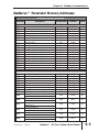
SureServo™ Parameter Memory Addresses
Parameter Memory Addresses
Parameter
Description
Modbus
Decimal
Octal
40001
40002
40003
40004
40005
40006
40007
40008
40009
40010
40011
40012
40013
40014
40015
40016
40017
40018
40019
0
1
2
3
4
5
6
7
10
11
12
13
14
15
16
17
20
21
22
0100
0101
0102
0103
0104
0105
0106
0107
0108
40257
40258
40259
40260
40261
40262
40263
40264
40265
400
401
402
403
404
405
406
407
410
0109
40266
411
010A
40267
412
010B
40268
413
010C
40269
414
010D
40270
415
010E
40271
416
Hexadecimal
Group 0: Monitor Parameters
P0-00
P0-01
P0-02
P0-03
P0-04
P0-05
P0-06
P0-07
P0-08
P0-09
P0-10
P0-11
P0-12
P0-13
P0-14
P0-15
P0-16
P0-17
P0-18
Software Version
Drive Fault Code
Drive Status (Front Panel Display)
Analog Monitor Outputs
Status Monitor 1
Status Monitor 2
Status Monitor 3
Status Monitor 4
Status Monitor 5
Block Transfer Parameter 1
Block Transfer Parameter 2
Block Transfer Parameter 3
Block Transfer Parameter 4
Block Transfer Parameter 5
Block Transfer Parameter 6
Block Transfer Parameter 7
Block Transfer Parameter 8
Output Functions Status
Servo On Time Record
0000
0001
0002
0003
0004
0005
0006
0007
0008
0009
000A
000B
000C
000D
000E
000F
0010
0011
0012
Group 1: Basic Parameters
P1-00
P1-01
P1-02
P1-03
P1-04
P1-05
P1-06
P1-07
P1-08
P1-09
P1-10
P1-11
P1-12
P1-13
P1-14
2nd Ed, Rev B
External Pulse Type Input
Control Mode and Output Direction
Speed and Torque Limit
Output Polarity Setting
Analog Monitor Output Scaling 1 (ch 1)
Analog Monitor Output Scaling 2 (ch 2)
Analog Speed Command Low-pass Filter
Analog Torque Command Low-pass Filter
Position Command Low-pass Filter
Velocity Command 1
Speed Limit 1
Velocity Command 2
Speed Limit 2
Velocity Command 3
Speed Limit 3
Torque Command 1
Torque Limit 1
Torque Command 2
Torque Limit 2
Torque Command 3
Torque Limit 3
08/2011
SureServo™ AC Servo Systems User Manual
6–3
Chapter 6: Modbus Communications
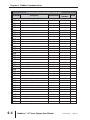
Parameter Memory Addresses (continued)
Parameter
Description
Hexadecimal
Modbus
Decimal
Octal
Group 1: Basic Parameters (continued)
P1-15
P1-16
P1-17
P1-18
P1-19
P1-20
P1-21
P1-22
P1-23
P1-24
P1-25
P1-26
P1-27
P1-28
P1-29
P1-30
P1-31
P1-32
P1-33
P1-34
P1-35
P1-36
P1-37
P1-38
P1-39
P1-40
P1-41
P1-42
P1-43
P1-44
P1-45
P1-46
P1-47
P1-48
P1-49
P1-50
6–4
Position Command 1- Revolutions
010F
40272
417
Position Command 1- Pulse
0110
40273
420
Position Command 2- Revolutions
0111
40274
421
Position Command 2- Pulse
0112
40275
422
Position Command 3- Revolutions
0113
40276
423
Position Command 3- Pulse
0114
40277
424
Position Command 4- Revolutions
0115
40278
425
Position Command 4- Pulse
0116
40279
426
Position Command 5- Revolutions
0117
40280
427
Position Command 5- Pulse
0118
40281
430
Position Command 6- Revolutions
0119
40282
431
Position Command 6- Pulse
011A
40283
432
Position Command 7- Revolutions
011B
40284
433
Position Command 7- Pulse
011C
40285
434
Position Command 8- Revolutions
011D
40286
435
Position Command 8- Pulse
011E
40287
436
Motor Code
011F
40288
437
Motor Stop Code
0120
40289
440
Position Control Mode
0121
40290
441
Acceleration Time
0122
40291
442
Deceleration Time
0123
40292
443
Acceleration/Deceleration S-curve
0124
40293
444
Inertia Mismatch Ratio
0125
40294
445
Zero Speed Output Threshold
0126
40295
446
Target Speed Output Threshold
0127
40296
447
Analog Full Scale Velocity Command/Limit
0128
40297
450
Analog Full Scale Torque Command/Limit
0129
40298
451
On Delay Time of Electromagnetic Brake
012A
40299
452
Off Delay Time of Electromagnetic Brake
012B
40300
453
Electronic Gear Numerator 1
012C
40301
454
Electronic Gear Denominator
012D
40302
455
Encoder Output Scaling Factor
012E
40303
456
Homing Mode
012F
40304
457
Homing Speed 1 - Fast Search Speed
0130
40305
460
Homing Speed 2 - Creep Speed
0131
40306
461
Home Position Offset (revolutions)
0132
40307
462
SureServo™ AC Servo Systems User Manual
2nd Ed, Rev B
08/2011
Chapter 6: Modbus Communications
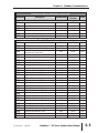
Parameter Memory Addresses (continued)
Parameter
Description
Hexadecimal
Modbus
Decimal
Octal
Group 1: Basic Parameters (continued)
P1-51
P1-52
P1-53
P1-54
P1-55
P1-56
Home Position Offset (counts)
0133
40308
463
Regenerative Resistor Value
0134
40309
464
Regenerative Resistor Capacity
0135
40310
465
In Position Window
0136
40311
466
Maximum Speed Limit
0137
40312
467
Overload Output Warning Threshold
0138
40313
470
Group 2: Extended Parameters
P2-00
P2-01
P2-02
Position Loop Proportional Gain (KPP)
0200
40513
1000
Position Loop Gain Boost
0201
40514
1001
Position Feed Forward Gain (KFF)
0202
40515
1002
P2-03
Smooth Constant of
Position Feed Forward Gain
0203
40516
1003
P2-04
P2-05
P2-06
P2-07
P2-08
P2-09
P2-10
P2-11
P2-12
P2-13
P2-14
P2-15
P2-16
P2-17
P2-18
P2-19
P2-20
P2-21
P2-22
P2-23
P2-24
P2-25
P2-26
P2-27
P2-28
Velocity Loop Proportional Gain (KVP)
0204
40517
1004
Velocity Loop Gain Boost
0205
40518
1005
Velocity Loop Integral Compensation
0206
40519
1006
Velocity Feed Forward Gain
0207
40520
1007
Factory Defaults and Security
0208
40521
1010
Debounce Filter
0209
40522
1011
Digital Input Terminal 1 (DI1)
020A
40523
1012
Digital Input Terminal 2 (DI2)
020B
40524
1013
Digital Input Terminal 3 (DI3)
020C
40525
1014
Digital Input Terminal 4 (DI4)
020D
40526
1015
Digital Input Terminal 5 (DI5)
020E
40527
1016
Digital Input Terminal 6 (DI6)
020F
40528
1017
Digital Input Terminal 7 (DI7)
0210
40529
1020
Digital Input Terminal 8 (DI8)
0211
40530
1021
Digital Output Terminal 1 (DO1)
0212
40531
1022
Digital Output Terminal 2 (DO2)
0213
40532
1023
Digital Output Terminal 3 (DO3)
0214
40533
1024
Digital Output Terminal 4 (DO4)
0215
40534
1025
Digital Output Terminal 5 (DO5)
0216
40535
1026
Notch Filter (resonance suppression)
0217
40536
1027
Notch Filter Attenuation (resonance suppress.)
0218
40537
1030
Low-pass Filter (resonance suppression)
0219
40538
1031
External Anti-Interference Gain
021A
40539
1032
Gain Boost Control
021B
40540
1033
Gain Boost Switching Time
021C
40541
1034
2nd Ed, Rev B
08/2011
SureServo™ AC Servo Systems User Manual
6–5
Chapter 6: Modbus Communications
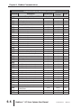
Parameter Memory Addresses (continued)
Parameter
Description
Hexadecimal
Modbus
Decimal
Octal
Group 2: Extended Parameters (continued)
P2-29
P2-30
P2-31
P2-32
P2-34
P2-35
P2-36
P2-37
P2-38
P2-39
P2-40
P2-41
P2-42
P2-43
P2-44
P2-45
P2-46
P2-47
P2-48
P2-49
P2-50
P2-51
P2-52
P2-53
P2-54
P2-55
P2-56
P2-57
P2-58
P2-59
P2-60
P2-61
P2-62
Gain Boost Switching Condition
021D
40542
1035
Auxiliary Function
021E
40543
1036
Auto and Easy Mode Response Level
021F
40544
1037
Tuning Mode
0220
40545
1040
Overspeed Fault Threshold
0222
40547
1042
Position Deviation Fault Window
0223
40548
1043
Position 1 Velocity
0224
40549
1044
Position 2 Velocity
0225
40550
1045
Position 3 Velocity
0226
40551
1046
Position 4 Velocity
0227
40552
1047
Position 5 Velocity
0228
40553
1050
Position 6 Velocity
0229
40554
1051
Position 7 Velocity
022A
40555
1052
Position 8 Velocity
022B
40556
1053
Digital Output Mode
022C
40557
1054
Index Mode Output Signal Delay Time
022D
40558
1055
Index Mode - Stations
022E
40559
1056
Position Deviation Clear Delay Time
022F
40560
1057
Backlash Compensation (index mode)
0230
40561
1060
Jitter Suppression
0231
40562
1061
Clear Position Mode
0232
40563
1062
Servo On Command
0233
40564
1063
Dwell Time 1 (auto index mode)
0234
40565
1064
Dwell Time 2 (auto index mode)
0235
40566
1065
Dwell Time 3 (auto index mode)
0236
40567
1066
Dwell Time 4 (auto index mode)
0237
40568
1067
Dwell Time 5 (auto index mode)
0238
40569
1070
Dwell Time 6 (auto index mode)
0239
40570
1071
Dwell Time 7 (auto index mode)
023A
40571
1072
Dwell Time 8 (auto index mode)
023B
40572
1073
Electronic Gear Numerator 2
023C
40573
1074
Electronic Gear Numerator 3
023D
40574
1075
Electronic Gear Numerator 4
023E
40575
1076
P2-63
Velocity and Position Deviation
Scaling Factor
023F
40576
1077
P2-64
P2-65
Advanced Torque Limit Mode
0240
40577
1100
Special Input Functions
0241
40578
1101
6–6
SureServo™ AC Servo Systems User Manual
2nd Ed, Rev B
08/2011
Chapter 6: Modbus Communications
Parameter Memory Addresses (continued)
Parameter
Description
Hexadecimal
Modbus
Decimal
Octal
Group 3: Communication Parameters
P3-00
P3-01
P3-02
P3-03
P3-04
P3-05
P3-07
P3-08
Communication Address
0300
40769
1400
Transmission Speed
0301
40770
1401
Communication Protocol
0302
40771
1402
Communication Fault Action
0303
40772
1403
Communication Watchdog Time Out
0304
40773
1404
Communication Selection
0305
40774
1405
Communication Response Delay Time
0307
40776
1407
Digital Input Software Control Mask
0308
40777
1410
Group 4: Diagnostic Parameters
P4-00
P4-01
P4-02
P4-03
P4-04
P4-05
P4-06
P4-07
P4-09
P4-20
P4-21
P4-22
P4-23
2nd Ed, Rev B
Fault Record (N) (most recent)
0400
41025
2000
Fault Record (N-1)
0401
41026
2001
Fault Record (N-2)
0402
41027
2002
Fault Record (N-3)
0403
41028
2003
Fault Record (N-4)
0404
41029
2004
Jog Function
0405
41030
2005
Force Outputs Command
0406
41031
2006
Input Status
0407
41032
2007
Output Status
0409
41034
2011
Analog Monitor 1 Offset (ch 1)
0414
41045
2024
Analog Monitor 2 Offset (ch 2)
0415
41046
2025
Analog Velocity Input Offset
0416
41047
2026
Analog Torque Input Offset
0417
41048
2027
08/2011
SureServo™ AC Servo Systems User Manual
6–7
Chapter 6: Modbus Communications
Connecting to DirectLOGIC PLCs
The following steps explain how to connect and communicate with the SureServo
drives using DirectLOGIC PLCs.
Step 1: Modbus RTU Master PLCs
The SureServo™ servo drives will communicate with the following DirectLOGIC
CPUs using the Modbus RTU protocol.
Modbus RTU Master Support
MRX/MWX Instructions
RX/WX Instructions
DL06 or DL-260 CPU port 2
DL05, DL06, DL250-1 or DL260 CPU port 2
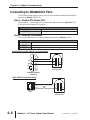
Step 2: Make the Connections
There are several means of communicating serially from a Directlogic PLC.
CPU Connections
RS-232
RS-485
RS-422
DL05/DL06/DL250-1/DL260 port 2
DL06/DL260 port 2
DL06/DL250-1/DL260 port 2
DL06/DL250-1/DL260: RS-232 Connection Wiring
6
1
TXD
RXD
7
11
0V
6
2
RX
3
TX
CTS
5
3
4
GND
1
2
4
RTS
5
10 15
SureServo
Comm Port CN3
DL06/DL250-1/DL260
CPU Port 2
DL05: RS-232 Connection Wiring
1
1 0V
6
3 RXD
RX
4 TXD
TX
4
6
6–8
SureServo™ AC Servo Systems User Manual
3
GND
2
DL05 CPU
Port 2
5
1
SureServo
Comm Port CN3
2nd Ed, Rev B
08/2011
Chapter 6: Modbus Communications
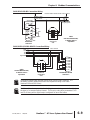
DL06/DL260: RS-485 Connection Wiring
120⏲ Termination Resistor at both ends of network
TXD+ / RXD+
Signal GND
RXD–
TXD– / RXD–
GND
Connect shield
to signal ground
6
1
11
0V
RTS+
TXD+
RXD+
TX–
6
RX–
4
RTS–
CTS+
2
TX+
5
RX+
3
GND
1
CTS–
5 10
15
SureServo
Comm Port
CN3
TXD–
DL06/DL260
CPU Port 2
Cable:
Use SVC-MDCOM-CBL,
or Belden 9841 or
equivalent
DL06/DL250-1/DL260: RS-422 Connection Wiring
RX+
RX–
TX+
TX–
Signal GND
Cable:
Use SVC-MDCOM-CBL,
or Belden 9729 or
equivalent
120⏲ Termination Resistor at both ends of network
TX–
6
5
TX+
RX–
4
3
RX+
2
1
GND
SureServo
Comm Port
CN3
9 TXD+
10 TXD–
13 RXD+
6 RXD–
11 RTS+
12 RTS–
14 CTS+
15 CTS–
7 0V
DL06/DL250-1/DL260
CPU Port 2
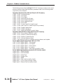
Termination Resistors are required at both ends of RS-422/485 networks. It is
necessary to select resistors that match the impedance rating of the cable
(between 100 and 500 Ohms.)
SureServo drives have a provision for shutting down control or power to the drive in
the event of a communications timeout. This is set up using drive parameters P3-03
and P3-04 along with a digital output configured for servo fault alarm.
2nd Ed, Rev B
08/2011
SureServo™ AC Servo Systems User Manual
6–9
Chapter 6: Modbus Communications
Step 3: Confirm/Set Servo Communication Parameters
Most drive parameters can be written to or updated from a master controller using
Modbus communications. However, the drive’s operational “run” commands (i.e Servo
On, Command Trigger, RESET, etc) can only be executed by controlling the drive’s
physical digital inputs.
The following SureServo™ communications parameters must match the
DirectLOGIC CPU port settings in order to establish communications. Refer to the
servo Communication parameters (P3-**) for available settings.
P3-00: Communication address (default 1) - PLC read/write instructions use comm
address to target a specific drive
P3-01: Communication baud rate (default 19200 bps)
P3-02: Communication protocol (default Modbus RTU mode <8 data bits, odd
parity, 1 stop bit>
P3-05: Communication Selection (default RS-232)
Other related Parameters to note:
P2-30: Aux Function - setting this parameter to (5) will disable “parameter write to
EEPROM” each time communications is attempted with the drive (default
0). This parameter setting is not retained when power is disconnected from
the drive.
The previous list of parameter settings is the minimum required to establish
communications with a DirectLOGIC PLC. There are several other parameters that
must be set through the drive keypad to configure the drive up for your application.
Step 4: Configure the DirectLOGIC CPU Port 2
The DirectLOGIC CPUs must be configured as a Modbus RTU master PLC to
communicate with the SureServo drives. This includes setting up the PLC
communication port parameters and creating ladder logic programming code that
uses read/write instructions to communicate with the drive(s).
The set up for all of the DirectLOGIC CPUs is very similar. Refer to the
appropriate CPU User Manual for the specifics on your DirectLOGIC CPU.
6–10
SureServo™ AC Servo Systems User Manual
2nd Ed, Rev B
08/2011
Chapter 6: Modbus Communications
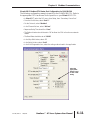
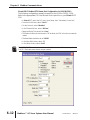
DirectLOGIC Modbus RTU Master Port Configuration for DL06/DL260
The following configuration example is specific to the DL06/DL260 CPU. Refer to
the appropriate CPU User Manual for the specifics on your DirectLOGIC CPU.
• In DirectSOFT, select the PLC menu, then Setup, then “Secondary Comm Port”
• From the Port list box, select “Port 2”
• For the Protocol, select “Modbus”
• In the Timeout list box, select “800 ms”
• Response Delay Time should be “0 ms”
• The Station Number should be set to “1” to allow the CPU to function as network
master
• The Baud Rate should be set at “19200”
• In the Stop Bits list box, select “1”
• In the Parity list box, select “Odd”
• In the Echo Suppression box, select the wiring method used in the application
Select the
appropriate
button based
on the comm
wiring
2nd Ed, Rev B
08/2011
SureServo™ AC Servo Systems User Manual
6–11
Chapter 6: Modbus Communications
DirectLOGIC Modbus RTU Master Port Configuration for DL05/DL250-1
The following configuration example is specific to the DL05 or DL250-1 CPU.
Refer to the appropriate CPU User Manual for the specifics on your DirectLOGIC
CPU.
• In DirectSOFT, select the PLC menu, then Setup, then “Secondary Comm Port”
• From the Port list box, select “Port 2”
• For the Protocol, select “Modbus”
• In the Timeout list box, select “800 ms”
• Response Delay Time should be “0 ms”
• The Station Number should be set to “1” to allow the CPU to function as network
master
• The Baud Rate should be set at “19200”
• In the Stop Bits list box, select “1”
• In the Parity list box, select “Odd”
The DL05/DL250-1 network instructions used in Master mode will access only slaves
1 to 90. Each slave must have a unique number.
6–12
SureServo™ AC Servo Systems User Manual
2nd Ed, Rev B
08/2011
Chapter 6: Modbus Communications
SureServo™ / DirectLOGIC PLC Control Example
SureServo™ Block Transfer Function
A group of Status Monitor Registers (P0-04 to P0-08) and a group of Block Data
Registers (P0-09 to P0-16) are available in the SureServo drive. These continuous
blocks of registers can be used to "group" miscellaneous drive parameters together
allowing you to read/write the desired parameters in one block instead of having to
use a Read/Write command for each parameter.
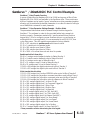
SureServo™ Drive Parameter Settings Example - Position Mode
The parameters listed below must be entered through the drive keypad or
SureServo™ Pro software in order for the provided ladder logic example to
function properly. (Parameters marked with * must be entered from the drive
keypad only.) Prior to configuring a new SureServo drive or re-configuring an
existing drive for a new application, it is recommended to set P2-08 = 10, then
cycle drive power. This will reset drive parameters to factory defaults.
P1-01 = 101: sets drive to position mode with internal control
P1-33 = 1: sets drive to incremental mode
P1-34 = 500: sets the accel time to 500ms
P1-35 = 500: sets the decel time to 500ms
P1-36 = 1000: >1 to allow the accel and decel to operate
Read transfer block from drive
P0-04 = 1: assigns motor feedback rotation to Status Monitor 1
P0-05 = 0: sets the motor feedback pulse to Status Monitor 2
P0-06 = 6: assigns motor rpm to Status Monitor 3
P0-07 = 11: assigns current % load to Status Monitor 4
P0-08 = 12: assigns peak % load to Status Monitor 5
* P0-09 = 409: assigns the digital output word to Block Transfer 1
* P0-10 = 407: assigns the digital input word to Block Transfer 2
Write transfer block to drive
* P0-11 = 21E: assigns Aux Function EEPROM write control to Block Transfer 3
* P0-12 = 10F: assigns the 1st position command revolution word to Block Trans 4
* P0-13 = 110: assigns the 1st position command pulse word to Block Transfer 5
* P0-14 = 224: assigns the 1st position velocity reference to Block Transfer 6
P2-10 = 101: assigns digital input 1 to Servo On bit
P2-11 = 108: assigns digital input 2 to Command Trigger bit
P2-12 = 104: assigns digital input 3 Pulse Clear
P2-13 = 111: assigns digital input 4 Position Zero
P2-14 = 102: assigns digital input 5 to Reset bit
P2-15 = 22: assigns digital input 6 to CWL limit (NC)
P2-16 = 23: assigns digital input 7 to CCWL limit (NC)
P2-17 = 21: assigns digital input 8 to External Fault (NC)
P2-18 = 101: assigns digital output 1 to Servo Ready
P2-19 = 103: assigns digital output 2 to Low Speed
P2-20 = 109: assigns digital output 3 to Home Search
P2-21 = 105: assigns digital output 4 to In Position
P2-22 = 7: assigns digital output 5 to Servo Fault (NC)
* These parameters must be entered using the drive keypad.
2nd Ed, Rev B
08/2011
SureServo™ AC Servo Systems User Manual
6–13
Chapter 6: Modbus Communications
The following list provides the DirectLOGIC PLC V-memory locations and control
bits along with the associated SureServo parameters used in the following ladder
logic drive control example.
Parameters Read from drive (RX) and Placed in PLC V-memory
V3000 - P0-00: Firmware Version
V3001 - P0-01: Drive fault
V3002 - P0-02: Drive Status
V3003 - P0-03: Analog Monitor Output
V3004 - P0-04: Motor Feedback Rotation
V3005 - P0-05: Motor Feedback Pulse
V3006 - P0-06: Motor RPM
V3007 - P0-07: Current Load (% of rated torque)
V3010 - P0-08: Peak Load (% of rated torque since powerup)
V3011 - P0-09: Digital Output Word
V3012 - P0-10: Digital Input Word
V3013 - P0-11: Read drive EEPROM control value
Parameters/Values Written to drive (WX) from PLC V-memory
V2000 - P0-11: Drive write to EEPROM control
V2001 - P0-12: Position Command Revolutions
V2002 - P0-13: Position Command pulse
V2003 - P0-14: Velocity Reference (rpm)
V2013 - User memory location to compare velocity reference and update
Drive’s digital outputs mapped from V3011 to VC120
C120 - P2-18: Digital output 1 - Servo Ready
C121 - P2-19: Digital output 2 - Low Speed
C122 - P2-20: Digital output 3 - Home Search
C123 - P2-21: Digital output 4 - In position
C124 - P2-22: Digital output 5 - Servo Fault (normally closed)
Drive’s digital input terminals connected to PLC discrete outputs
Digital Input 1 - SERVO ENABLE
Digital Input 2 - CMD TRIGGER
Digital Input 3 - Pulse Clear
Digital Input 4 - Position Zero
Digital Input 5 - RESET
Digital Input 6 - CWL Limit (normally closed)
Digital Input 7 - CCWL Limit (normally closed)
Digital Input 8 - External Fault (normally closed)
6–14
SureServo™ AC Servo Systems User Manual
2nd Ed, Rev B
08/2011
Chapter 6: Modbus Communications
DirectLOGIC Ladder Logic Programming Example
The setup for all of the DirectLOGIC CPUs is very similar. Refer to the
appropriate CPU User Manual for the specifics on your particular DirectLOGIC
CPU model.
The following ladder program shows an example of how to control the SureServo
drive (configured for Position Mode) using communications instructions via the
Modbus RTU protocol. The drive should be set up and tested for communications
before it is connected to a load.
WARNING: A drive should never be connected to a load until any applicable
communication programs have been proven.
This program is for example purposes only and not intended for a specific application.
The drive parameters listed on the previous pages are required for the following example
program to function properly.
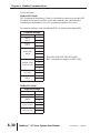
Rung 1 initializes the drive on first scan. The motor pulse and revolutions registers
are set to zero and the motor velocity reference is set to 3000rpm.
First Scan
SP0
LD
1
K5
OUT
V2000
K5 disables
“write parameters
to drive EEPROM”
Drive EEPROM
write control
LD
K0
OUT
V2001
Position command
revolution word
LD
K0
OUT
V2002
Position command
pulse word
LD
K3000
BIN
OUT
V2003
Motor velocity
reference (rpm)
(example program cont. on next page)
2nd Ed, Rev B
08/2011
SureServo™ AC Servo Systems User Manual
6–15
Chapter 6: Modbus Communications
DirectLOGIC Ladder Programming Example (continued)
In many drive applications, electromagnetic interference can at times cause
frequent, short duration, communication errors. Unless the application
environment is perfect, an occasional communication error will occur. In order to
distinguish between these non-fatal transients and a genuine communication
failure, you may want to use the instructions as shown in Rungs 2 and 3.
Rung 2 monitors the number of times that the PLC attempts to communicate with the
drive. When the PLC’s communication attempts are successful, SP116 (port busy) will
count up and SP117 (comm error) will not count. Once the count reaches 9999, the
counter will reset and resume counting.
Port Busy
SP116
2
CT0
CNT
Comm transaction count
CT0
K9999
Rung 3 monitors the number of times the PLC fails in communicating with the drive.
Port Comm
Error
SP117
3
CT0
CNT
Comm error count
CT1
K9999
Alternative resets/control bits can be used in your application program.
(example program cont. on next page)
6–16
SureServo™ AC Servo Systems User Manual
2nd Ed, Rev B
08/2011
Chapter 6: Modbus Communications
DirectLOGIC Ladder Programming Example (continued)
The Read(RX) and Write(WX) commands are supported in the DL05/06/250-1/260
DirectLOGIC CPUs. These instructions use octal addressing only, so the octal
equivalent of the Parameter’s Modbus addresses must be used.
Rung 4 reads the first 12 Monitor Parameters (P0-00 to P0-11) in the drive and
places the values in V3000 - V3013 in the PLC. (Octal V0 - V13 equals Modbus
40001 - 40012).
Port Busy
SP116
Comm
Interlock
C10
Kf201
f2 = DL05/06 port 2
(f1 = DL250-1/260 port 2)
01 = Slave Address
K24
# of bytes to read
LD
4
LD
LDA
O3000
Destination
address in PLC
V0
Source memory
address in drive
RX
Rung 5 writes 4 words (V2000 - V2003) from the PLC to drive Block Read/Write
registers P0-11 to P0-14 (Octal V13 - V16 equals Modbus 40012 - 40015).
Port Busy
SP116
Comm
Interlock
C10
LD
Kf201
5
f2 = DL05/06 port 2
(f1 = DL250-1/260 port 2)
01 = Slave Address
LD
K8
LDA
# of bytes to write
O2000
Source memory
address in PLC
V13
Destination
address in drive
WX
C10
( RST )
Comm Interlock
(example program cont. on next page)
2nd Ed, Rev B
08/2011
SureServo™ AC Servo Systems User Manual
6–17
Chapter 6: Modbus Communications
Alternate Rungs 4 and 5 for use with DL06/DL260 PLC
The DL06/260 CPUs support the Modbus Read (MRX) and Modbus Write (MWX)
instructions. These instructions allow you to enter Modbus Slave Memory
Addresses (no need to use octal addressing conversions to communicate with the
drive).
Rung 4 reads the first 12 (P0-00 to P0-11) Monitor Parameters from the drive and
places the values in V3000 - V3013 in the PLC.
Port Busy
SP116
Comm
Interlock
C10
4
MRX
Port Number:
K2
Slave Address:
K1
Function Code:
03 - Read Holding Registers
Start Slave Memory Address:
40001
Start Master Memory Address:
V3000
Number of Elements:
12
Modbus Data type:
584/984 Mode
Exception Response Buffer:
V5005
Rung 5 writes 4 words (V2000 - V2003) from the PLC to drive Block Transfer
Registers P0-11 - P0-14 (Modbus 40012 - 40015).
Port Busy
SP116
Comm
Interlock
C10
5
MWX
Port Number:
K2
Slave Address:
K1
Function Code:
16 - Preset Multiple Registers
Start Slave Memory Address:
40012
Start Master Memory Address:
V2000
Number of Elements:
4
Modbus Data type:
584/984 Mode
Exception Response Buffer:
V5000
C10
( RST )
Comm Interlock
(example program cont. on next page)
6–18
SureServo™ AC Servo Systems User Manual
2nd Ed, Rev B
08/2011
Chapter 6: Modbus Communications
DirectLOGIC Ladder Programming Example (continued)
Rung 6 maps the drive’s digital output word that was read using the RX or MRX
instruction from V3011 to C120 - C124 for bit level use.
Always on
SP1
LD
6
Drive digital
output word
V3011
OUT
VC120
Rung 7 enables the drive (digital input 1 = Servo Enable) when C1 is turned on. Y0
is connected to drive digital input 1.
Y0
C1
( SET )
7
Servo enable control
Rungs 8 loads the position (revolutions and pulse) counts to the drive when C2 is
turned on. The registers are written by the WX or MWX instruction.
C2
LD
8
K3
BIN
Note: Constants are used in this
example program. User V-memory
locations can be used to store settings
(drive requires binary format).
OUT
Position command
revolutions word
V2001
LD
K500
BIN
OUT
Position command
pulse word
V2002
C10
C11
( SET )
Interlocks
(example program cont. on next page)
2nd Ed, Rev B
08/2011
SureServo™ AC Servo Systems User Manual
6–19
Chapter 6: Modbus Communications
DirectLOGIC Ladder Programming Example (continued)
Rung 9: C12 is triggered once the Position is loaded into the drive.
C11
Comm Interlock
C10
C11
( RST )
9
C12
(
)
PD
Positions loaded
Rung 10 sets the drive’s Command Trigger input to begin the motor position
movement and sets C13, the drive triggered bit. Y1 is connected to drive digital input
2.
C3
Servo Ready
C120
10
Y1
( SET )
CMD Trigger
C13
( SET )
Drive triggered
Rung 11: If the drive has been triggered and is not in position (motor is moving),
the drive input CMD trigger and drive triggered flag are reset.
Drive
Triggered
C13
In Position
C123
Y1
( RST )
11
CMD Trigger
C13
( RST )
Drive triggered
Rung 12: If C4 is turned on, drive faults and the ladder logic is reset.
Y2 is connected to drive input 3. Y4 is connected to drive input 5.
C4
12
Y2
(
OUT
C10
)
Clear Pulse
C13
( RST )
Control Bits
Y0
PLC outputs
connected to
drive reset
Y4
( RST )
(example program cont. on next page)
6–20
SureServo™ AC Servo Systems User Manual
2nd Ed, Rev B
08/2011
Chapter 6: Modbus Communications
DirectLOGIC Ladder Programming Example (continued)
Rung 13: If the EEPROM write control register (V2000) is not equal to the value
read (RX or MWX) and stored in V3013, C10 will be set to enable the WX or MWX
command (rung 4). This will update the drive with the value in V2000.
For example, drive parameter P2-30 (write to EEPROM control) is not retentive
during drive power cycle, so the read value stored in V3013 will be 0 (zero) and
the value in V2000 may be (5). This will enable the rung 13 and cause rung 4 to
execute the write to drive transfer block.
EEPROM
write status
V2000
EEPROM
read status
V3013
Comm Interlock
C10
( SET )
=
13
Rung 14: If the motor velocity reference register (V2003) is not equal to the
previous velocity value stored in V2013 (user V-memory location), the WX
command (rung 4) will execute and write the new velocity reference to the drive
and will map the current value (V2003) to user V-memory location V2013.
Current Motor Velocity
Reference write
V2003
14
=
Desired Motor Velocity
Reference value
V2013
LD
V2013
Motor Velocity
Reference (rpm)
V2003
User location to
store current motor
velocity reference (rpm)
OUT
C10
(
SET
)
Comm Interlock
Rung 15: All ladder logic programs must be terminated with an (END) command.
( END )
15
2nd Ed, Rev B
08/2011
SureServo™ AC Servo Systems User Manual
6–21
Chapter 6: Modbus Communications
DirectLOGIC Ladder Programming Example – Multiple Drives
The set up for all of the DirectLOGIC CPUs is very similar. Refer to the
appropriate CPU User Manual for the specifics on your DirectLOGIC CPU.
The following ladder program shows an example of a DL06 or DL260 CPU port 2
controlling two SureServo™ drives using MRX/MWX instructions. The drive must
be set up and tested for communications before it is connected to a load. See the
previous ladder example for rung instruction explanations.
WARNING: A drive should never be connected to a load until any applicable
communication programs have been proven.
This program is for example purposes only and not intended for a specific application.
Port Busy
SP116
1
CT0
CNT
Comm transaction count
CT0
K9999
Port
Comm Error
SP117
2
CNT
Comm error count
CT1
CT0
K9999
Rung 3 contains a counter which is used to determine which MRX or MWX
instruction to execute. Its purpose is to prevent multiple MRX/MWX rungs being
active at the same time. Since the counter may only have one value at any
particular time, only a single rung may be executed.
Port Busy
SP116
3
CT2
CNT
Comm transaction count
CT2
K4
(example program cont. on next page)
6–22
SureServo™ AC Servo Systems User Manual
2nd Ed, Rev B
08/2011
Chapter 6: Modbus Communications
DirectLOGIC Modbus Ladder Programming -Multiple Drives, cont.
Please also note that adding additional MRX/MWX rungs would be accomplished
simply by increasing the K4 value to the new total number of MRX and MWX
instructions needed. SP116 is used to increment the counter so that each time an
MRX or MWX is executed, the counter then enables the next MRX or MWX once
the current MRX or MWX is complete.
Port Busy
SP116
CTA2
=
4
Port Busy
SP116
CTA2
K1
=
5
Port Busy
SP116
CTA2
K2
=
6
Port Busy
SP116
CTA2
K3
=
7
2nd Ed, Rev B
K0
08/2011
MRX
Port Number:
K2
Slave Address:
K1
Function Code:
03 - Read Holding Registers
Start Slave Memory Address:
40001
Start Master Memory Address:
V3000
Number of Elements:
12
Modbus Data type:
584/984 Mode
Exception Response Buffer:
V405
MWX
Port Number:
K2
Slave Address:
K1
Function Code:
16 - Preset Multiple Registers
Start Slave Memory Address:
40012
Start Master Memory Address:
V2000
Number of Elements:
4
Modbus Data type:
584/984 Mode
Exception Response Buffer:
V400
MRX
Port Number:
K2
Slave Address:
K2
Function Code:
03 - Read Holding Registers
Start Slave Memory Address:
40001
Start Master Memory Address:
V3020
Number of Elements:
12
Modbus Data type:
584/984 Mode
Exception Response Buffer:
V415
MWX
Port Number:
K2
Slave Address:
K2
Function Code:
16 - Preset Multiple Registers
Start Slave Memory Address:
40012
Start Master Memory Address:
V2020
Number of Elements:
4
Modbus Data type:
584/984 Mode
Exception Response Buffer:
V410
SureServo™ AC Servo Systems User Manual
6–23
Chapter 6: Modbus Communications
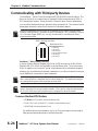
Communicating with Third-party Devices
The SureServo™ Serial Comm Port supports RS-232/422/485 communications. The
drive can be set up to communicate on standard Modbus networks using ASCII or
RTU transmission modes. Using the drive’s Communication Protocol parameters,
you can select the desired mode, data bits, parity, and stop bits. The communication
parameters must be the same for all devices on a Modbus network.
Most drive parameters can be written to or updated from a master controller using
Modbus communications. However, the drive’s operational “run” commands (i.e Servo
On, Command Trigger, RESET, etc) can only be executed by controlling the drive’s
physical digital inputs.
IEEE 1394 Plug Connector
Serial Comm Port
6
5
4
3
2
1
RS-232/422/485 Interface
1: GND (0V)
2: RS-232 TX
3: RS-422 RX+
4: RS-232 RX, RS-422 RX5: RS-422 TX+
6: RS-422 TX-
SureServo™ Block Transfer Function
A group of Status Monitor Registers (P0-04 to P0-08) and a group of Block Data
Registers (P0-09 to P0-16) are available in the SureServo drive. These continuous
block of registers can be used to "group" miscellaneous drive parameters together
allowing you to read/write the desired parameters in one block instead of having to
use a Read/Write command for each parameter.
P2-30 – setting this parameter to (5) will disable “parameter write to EEPROM” each
time communications is attempted with the drive (default 0). This parameter setting is
not retained when power is disconnected from the drive.
SureServo drives have a provision for shutting down control power to the output of the
drive in the event of a communications timeout. This is set up using drive parameters
P3-03 and P3-04, along with a digital output configured for servo fault alarm.
Common Modbus RTU Masters
• KEPDirect for PLCs (serial communications only)
• Think & Do Live 5.6, Studio 7.2.1 (serial communications only)
• MODSCAN from www.wintech.com
For additional technical assistance, go to our Technical support home page at:
http://support.automationdirect.com/technotes.html
6–24
SureServo™ AC Servo Systems User Manual
2nd Ed, Rev B
08/2011
Chapter 6: Modbus Communications
Modbus Protocol Modes
This section explains the specifics of the Modbus protocols. It is not necessary to
use this information if your drive control is capable of serving as a Modbus master
controller.
ASCII Mode:
Each 8-bit data is the combination of two ASCII characters. For example, a 1-byte
data: 64 Hex, shown as '64' in ASCII, consists of '6' (36Hex) and '4' (34Hex).
The following table shows the available hexadecimal characters and their
corresponding ASCII codes.
Character
‘0’
‘1’
‘2’
‘3’
‘4’
‘5’
‘6’
‘7’
ASCII Code
30H
31H
32H
33H
34H
35H
36H
37H
Character
‘8’
‘9’
‘A’
‘B’
‘C’
‘D’
‘E’
‘F’
ASCII Code
38H
38H
41H
42H
43H
44H
45H
46H
RTU Mode:
Each 8-bit data is the combination of two 4-bit hexadecimal characters. For
example, a 1-byte data: 64 Hex.
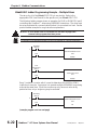
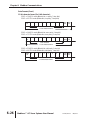
Modbus ASCII and RTU Data Format
10-bit character frame (For 7-bit character):
P3-02 = 00: ASCII mode (7 data bits, no parity, 2 stop bits)
Start
bit
0
1
2
3
4
5
6
Stop Stop
bit
bit
7-bit character
10-bit character frame
P3-02 = 01: ASCII mode (7 data bits, even parity, 1 stop bit)
Start
bit
0
1
2
3
4
5
6
Even Stop
parity bit
7-bit character
10-bit character frame
P3-02 = 02: ASCII mode (7 data bits, odd parity, 1 stop bit)
Start
bit
0
1
2
3
4
5
6
Odd Stop
parity bit
7-bit character
10-bit character frame
2nd Ed, Rev B
08/2011
SureServo™ AC Servo Systems User Manual
6–25
Chapter 6: Modbus Communications
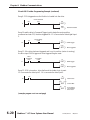
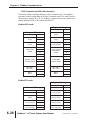
Data Formats (Cont.)
11-bit character frame (For 8-bit character):
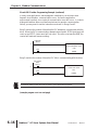
P3-02 = 03: ASCII mode (8 data bits, no parity, 2 stop bits)
P3-02 = 06: RTU mode (8 data bits, no parity, 2 stop bits)
Start
bit
0
1
2
3
4
5
6
7
Stop
bit
Stop
bit
8-bit character
11-bit character frame
P3-02 = 04: ASCII mode (8 data bits, even parity, 1 stop bit)
P3-02 = 07: RTU mode (8 data bits, even parity, 1 stop bit)
Start
bit
0
1
2
3
4
5
6
7
Even Stop
parity bit
7
Odd Stop
parity bit
8-bit character
11-bit character frame
P3-02 = 05: ASCII mode (8 data bits, odd parity, 1 stop bit)
P3-02 = 08: RTU mode (8 data bits, odd parity, 1 stop bit)
Start
bit
0
1
2
3
4
5
6
8-bit character
11-bit character frame
6–26
SureServo™ AC Servo Systems User Manual
2nd Ed, Rev B
08/2011
Chapter 6: Modbus Communications
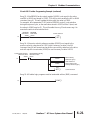
Communication Protocol
Modbus ASCII Mode:
STX
Start Character: (3AH)
ADR 1
ADR 0
CMD 1
Communication Address: 8-bit address consists of 2 ASCII codes
CMD 0
DATA (n-1)
.......
Contents of data: n x 8-bit data consists of 2n ASCII codes. n[]25
maximum of 50 ASCII codes
DATA 0
LRC CHK 1
LRC CHK 0
END 1
END-0
LRC check sum: 8-bit check sum consists of 2 ASCII codes
END characters: END 1=CR (0DH), END 0 =LF (0AH)
Modbus RTU Mode:
START
A silent interval of more than 10 ms
ADR
Communication Address: 8-bit address
CMD
DATA (n-1)
.......
Contents of data: n x 8-bit data,n<=25
DATA 0
CRC CHK Low
CRC CHK High
CRC check sum: 16-bit check sum consists of 2 8-bit characters
END
A silent interval of more than 10 ms
ADR (Communication Address)
Valid communication addresses are in the range of 0 to 254. A communication
address equal to 0 means broadcast to all SureServo drives. In this case, the drive
will not reply any message to the master device.
For example, communication to drive with address 16 decimal:
Modbus ASCII mode: (ADR 1, ADR 0)='1','0' => '1'=31H, '0'=30H
Modbus RTU mode: (ADR)=10H
2nd Ed, Rev B
08/2011
SureServo™ AC Servo Systems User Manual
6–27
Chapter 6: Modbus Communications
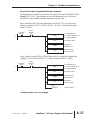
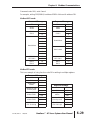
CMD (Command) and DATA (data characters)
The format of data characters depends on the command code. The available
command codes are described as follows: Command code: 03H, read N words.
The maximum value of N is 10. For example, reading continuous 2 words from
starting address 0200H of drive with address 01H.
Modbus ASCII mode:
Response Message
STX ':'
':'
ADR 1
ADR 0
'0'
CMD 1
CMD 0
'0'
Number of data
(Count by byte)
'0'
Command Message
STX
':'
ADR 1
ADR 0
'0'
CMD 1
CMD 0
'0'
'1'
'3'
'0'
Starting data
address
Number of data
(Count by word)
'2'
'0'
END 1
END 0
'3'
'4'
'0'
Content of starting
data address
0200H
'0'
'B'
'0'
'1'
'0'
'1'
'0'
'0'
Content data
address 0201H
'2'
LRC CHK 1
LRC CHK 0
'1'
'F'
'8'
'F'
'4'
'0'
LRC CHK 1
LRC CHK 0
CR
END 1
END 0
LF
'E'
'8'
CR
LF
Modbus RTU mode:
Response Message
ADR
01H
CMD
03H
Number of data
(Count by byte)
04H
Content of data
address 0200H
00H
Command Message
6–28
ADR
01H
CMD
03H
Starting data
address
02H
Number of data
(Count by word)
00H
CRC CHK Low
CRC CHK High
C5H
00H
02H
B3H
Content of data
address 0201H
CRC CHK Low
CRC CHK High
SureServo™ AC Servo Systems User Manual
'0'
B1H
1FH
40H
A3H
D4H
2nd Ed, Rev B
08/2011
Chapter 6: Modbus Communications
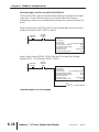
Command code: 06H, write 1 word
For example, writing 100(0064H) to address 0200H of drive with address 01H.
Modbus ASCII mode:
Command Message
Response Message
STX
':'
STX ':'
':'
ADR 1
ADR 0
'0'
ADR 1
ADR 0
'0'
CMD 1
CMD 0
'0'
CMD 1
CMD 0
'0'
'1'
'6'
'0'
'2'
'0'
Data Address
'1'
'6'
'0'
Data Address
'2'
'0'
'0'
'0'
'0'
'0'
'0'
'6'
Data Content
'4'
LRC CHK 1
LRC CHK 0
'9'
END 1
END 0
CR
'3'
LF
'0'
'6'
'4'
LRC CHK 1
LRC CHK 0
'9'
END 1
END 0
CR
'3'
LF
Modbus RTU mode:
This is an example of using function code 16 for writing to multiple registers.
Command Message
2nd Ed, Rev B
ADR
01H
CMD
10H
Starting data
address
02H
Number of data
(Count by byte)
04H
Content of data
address 0200H
00H
Content of data
address 0201H
02H
CRC CHK Low
CRC CHK High
CBH
08/2011
00H
02H
58H
34H
Response Message
ADR
01H
CMD
10H
Starting data
address
02H
Number of data
(Count by word)
00H
CRC CHK Low
CRC CHK High
4AH
00H
02H
08H
SureServo™ AC Servo Systems User Manual
6–29
Chapter 6: Modbus Communications
CHK (check sum)
Modbus ASCII Mode:
LRC (Longitudinal Redundancy Check) is calculated by summing up module 256,
the values of the bytes from ADR1 to last data character, then calculating the
hexadecimal representation of the 2's-complement negation of the sum.
For example, reading 1 word from address 0201H of the drive with address 01H.
Command Message
STX
':'
ADR 1
ADR 0
'0'
CMD 1
CMD 0
'0'
'1'
'3'
'0'
Starting data
address
'2'
'0'
'1'
'0'
Number of data
(Count by word)
01H+03H+02H+01H+00H+01H=08H,
the 2's complement negation of 08H is F8H.
'0'
'0'
'1'
LRC CHK 1
LRC CHK 0
END 1
END 0
'F'
'8'
CR
LF
Modbus RTU Mode:
Response Message
6–30
ADR
01H
CMD
03H
Starting data
address
02H
Number of data
(Count by word)
00H
CRC CHK Low
CRC CHK High
6FH
01H
02H
F7H
SureServo™ AC Servo Systems User Manual
2nd Ed, Rev B
08/2011
Chapter 6: Modbus Communications
CRC (Cyclical Redundancy Check) is calculated by the following steps:
Step 1: Load a 16-bit register (called CRC register) with FFFFH.
Step 2: Exclusive OR the first 8-bit byte of the command message with the low order
byte of the 16-bit CRC register, putting the result in the CRC register.
Step 3: Shift the CRC register one bit to the right with MSB zero filling. Extract and
examine the LSB.
Step 4: If the LSB of CRC register is 0, repeat step 3, else Exclusive or the CRC
register with the polynomial value A001H.
Step 5: Repeat step 3 and 4 until eight shifts have been performed. When this is
done, a complete 8-bit byte will have been processed
.Step 6: Repeat steps 2 to 5 for the next 8-bit byte of the command message.
Continue doing this until all bytes have been processed. The final contents of
the CRC register equal the CRC value.
When transmitting the CRC value in the message, the upper and lower bytes of the
CRC value must be swapped, i.e. the lower order byte will be transmitted first.
The following is an example of CRC generation using C language. The function
takes two arguments:
Unsigned char* data 씯 a pointer to the message buffer
Unsigned char length 씯 the quantity of bytes in the message buffer
The function returns the CRC value as a type of unsigned integer.
Unsigned int crc_chk(unsigned char* data, unsigned char length){
int j;
unsigned int reg_crc=0xFFFF;
while(length--){
reg_crc ^= *data++;
for(j=0;j<8;j++){
if(reg_crc & 0x01){ /* LSB(b0)=1 */
reg_crc=(reg_crc>>1) ^ 0xA001;
}else{
reg_crc=reg_crc >>1;
}
}
}
return reg_crc;
}
Modbus RTU mode is preferred. Limited support is available to Modbus ASCII users.
2nd Ed, Rev B
08/2011
SureServo™ AC Servo Systems User Manual
6–31
Chapter 6: Modbus Communications
BLANK
PAGE
6–32
SureServo™ AC Servo Systems User Manual
2nd Ed, Rev B
08/2011


![[VC120-2] [MENARDS] User Guide [FINAL] 20100618](http://vs1.manualzilla.com/store/data/005701495_1-e41e7e0d778d2f045f29de9890ac0ae7-150x150.png)