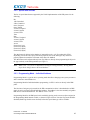
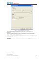
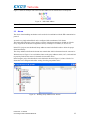
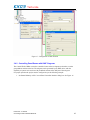
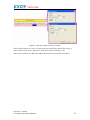
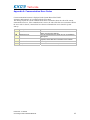
1
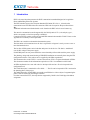
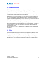
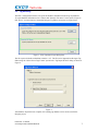
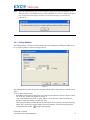
Tech-note
Connecting UniOP
to KNX EIB
Networks
This document describes how to configure
UniOP HMI for connection to KNX EIB
networks.
Sitek S.p.A.
Tn250
Ver. 1.02
Tech-note
Copyright © 2008 Sitek S.p.A. – Verona, Italy
Subject to change without notice
The information contained in this document is provided for informational purposes only. While
efforts were made to verify the accuracy of the information contained in this documentation, it is
provided “as is” without warranty of any kind.
Third-party brands and names are the property of their respective owners.
www.uniop.com
tn250-2.doc - 9.06.2008
Connecting UniOP to KNX EIB Networks
2
Tech-note
Contents
1
Introduction..................................................................................................................... 4
2
Principle of Operation ..................................................................................................... 5
2.1
Polling................................................................................................................ 5
3
Configuring the Designer Project .................................................................................... 6
3.1
Controller Setup................................................................................................. 6
3.2
Tag Handling ..................................................................................................... 7
3.2.1 Polling Attribute.................................................................................................. 8
3.2.2 Special Data formats........................................................................................ 10
3.2.3 Programming Mode – Individual Address ........................................................ 10
3.3
Alarms ............................................................................................................. 13
3.4
Using the Reserved Data Area ........................................................................ 15
3.4.1 Change Page with KNX Telegrams ................................................................. 15
3.4.2 Controlling Panel Buzzer with KNX Telegrams ................................................ 16
tn250-2.doc - 9.06.2008
Connecting UniOP to KNX EIB Networks
3
Tech-note
1 Introduction
KNX is the association that promotes the KNX communication standard designed to be applied to
Home and Building Electronic Systems.
The KNX standard, approved as European Standard EN 50090, EN 13321-1, is based on the
communication stack of EIB with some extensions. EIB is the acronym for European Installation
Bus.
Additional information and further details can be found on the KNX web site www.konnex.org.
The network communication media supported by the UniOP panels is TP-1, twisted pair, type 1,
which corresponds to a bus line operating at 9600 bit/s.
Connection to KNX systems requires the optional EIB communication module TCM17. Please see the
Appendix for a summary of the requirements.
The EIB is an event-driven decentralized automation system.
The information to be transmitted over the bus is organized in “telegrams” sent by a source to one or
more destination devices.
The bus line of EIB systems carries both data and power for the devices. The data is “modulated”
over the DC voltage of the power supply.
UniOP HMI panels are not powered from the network and they still need the usual the power supply.
The planning, design and commissioning of EIB/KNX installations are normally done using the ETS
configuration software. This software tool is supplied by the EIBA organization.
This document refers to the ETS™ 3 version of the software. ETS is a registered trademark of EIBA.
This document contains all the information required to use ETS 3 in combination with UniOP.
All EIB compliant devices come with a device descriptor delivered as a file to be imported in the
configuration tool.
The UniOP descriptor is contained in a file called “…”. The file can be imported in ETS 3 and used in
the planning phase of the project.
The model adopted by UniOP HMIs corresponds to an EIB device with no objects. Programming the
panel is done as usual using the Designer software.
For what concerns the ETS 3, the only function supported by UniOP is the UniOP physical address
assignment.
tn250-2.doc - 9.06.2008
Connecting UniOP to KNX EIB Networks
4
Tech-note
2 Principle of Operation
The UniOP implementation of the EIB communication protocol is designed to allow the access to the
Group Address blocks defined in the ETS 3 project. Depending on the nature of the group address the
user will be able to define the type of the access: read-only or read/write.
Tags in the Designer database correspond to group address in the ETS 3 project. A tag import process
is defined to transfer database information from ETS 3 to Designer.
All dynamic objects in a Designer project refer to a Group Address. At run-time, upon showing any
page of the project for the first time, the HMI panel may generate a sequence of read operations to
update the value of the status for all the objects present in that page. In case the target device does not
reply to UniOP request, the request is not repeated any more since next power cycle.
A local copy of the value of the status is then stored in an internal panel memory area.
From that moment, the HMI panel will not perform any read operation on the value of that item but
will rather monitor the network to collect all events related to that object.
Once the update process has been completed, the HMI panel continues monitoring the network for
any telegram associated to a group address of all of the objects defined in the project, even if they are
not currently displayed; the status of the panel memory is automatically updated according to the
valued transferred on the bus.
The status of objects on the screen is obtained from the internal memory, without generating any bus
read operation.
2.1
Polling
Some of the group addresses in the Designer database can be configured to have the Polling attribute
enabled.
When a group address tag has the Polling attribute enabled, the HMI panel will request the status of
the group issuing a read operation with the rate specified in the Designer Controller Setup (see next
chapter). The read operations are performed cyclically only when the object with that Group Address
is displayed in the current page.
The Polling attribute can be specified directly in Designer Tag Editor (see Tag Handling chapter).
tn250-2.doc - 9.06.2008
Connecting UniOP to KNX EIB Networks
5
Tech-note
3 Configuring the Designer Project
The communication protocol for EIB is called “EIB TP” and it is associated with the Designer file
D32Uplc210.dll.
The protocol can be selected from the Select Controller dialog box as shown in the figure below.
Figure 1 – Select Controller
3.1
Controller Setup
The Controller Setup dialog box is shown in the figure below.
Figure 2 – Controller Setup
Polling Time
Transmission Rate
defines how often the tags with the Polling attribute enabled are requested to
the network.
defines the interval of time between two consecutive write operations
performed by the panel.
tn250-2.doc - 9.06.2008
Connecting UniOP to KNX EIB Networks
6
Tech-note
3.2
Tag Handling
The ETS 3 configuration software can export the database information related to group addresses.
To export database information select “Extract data” from the File menu. Use the option “Export to
OPC Server” to export data in a format that Designer Tag Editor can import. See figure below.
Figure 3 – ETS 3 Database Export Dialog Box
The file exported with this method has extension “.esf”. The file can be imported into Designer Tag
Editor using the “Native Driver Tags Format” option in the “Tag Import Wizard” dialog as shown in
Figure 4.
Figure 4
After database import has been complete, the resulting tag database can be used as usual in the
Designer project.
tn250-2.doc - 9.06.2008
Connecting UniOP to KNX EIB Networks
7
Tech-note
Note:
The KNX communication driver requires proper configuration of the Tag Database in the
Designer project; downloading a project without database will result in a malfunction of the
unit. At each download Designer will show you the below message to remember this
requirement.
.
3.2.1 Polling Attribute
The Polling attribute, associated to each individual tag (corresponding to an EIB group address) can
be set in the Tag Editor as shown in the figure below.
Figure 5
The Polling attribute can also be set in the Designer software when a tag is used as a reference for an
object.
To do so, follow the procedure:
- In the Data Field Properties dialog box, click on the reference button as shown in Figure 6 below.
- The “Edit tags” window will appear (see Figure 7).
- Click on the rightmost part of the “Logical_address” cell to show the “Data Field Properties”
dialog box where the “Polling” attribute can be set.
- After closing the dialog with the OK button, please make sure to click once out of the line being
edited. This is required to save the changes into the tag database. The line being edited can be
recognized by the symbol “ ” placed at the beginning.
tn250-2.doc - 9.06.2008
Connecting UniOP to KNX EIB Networks
8
Tech-note
Figure 6
Figure 7
tn250-2.doc - 9.06.2008
Connecting UniOP to KNX EIB Networks
9
Tech-note
3.2.2 Special Data formats
The list of special data formats supported by the UniOP implementation of the EIB protocol is the
following:
Bit
1 Bit Controlled
3 Bits Controlled
Octet, Unsigned
Octet, Signed
2 Octets, Unsigned
2 Octets, Signed
2 Octets, Float
Time
Date
4 Octets, Unsigned
4 Octets, Signed
4 Octets, Float
Access
Uncertain (1 byte)
Uncertain (2 Bytes)
Uncertain (3 Bytes)
Uncertain (4 Bytes)
The data format for all tags in the database is imported from the “.esf” file produced by ETS 3.
Depending on how the ETS 3 project has been prepared, some of the data types may need to be
properly adjusted to match the real format of the data to be handled.
The data format can be adjusted directly from Tag Editor or directly when programming the object in
the page similarly to the Polling attribute (see Figure 7).
Note:
When a new “.esf” file is re- imported overwriting an existing dictionary, the Tag Editor
keeps all the changes done in the local database.
3.2.3 Programming Mode – Individual Address
Programming Mode is a special device operating mode that allows changing some system parameters
and is common to most EIB devices.
Programming Mode for Individual address programming via ETS 3 can be set directly in the HMI
panel.
The first time a Designer project made for the EIB communication driver is downloaded to an HMI
panel, the unit is assigned a default Individual Address. This address is the same normally assigned to
EIB devices from the manufacturer. The address value is: F/F/FF.
Programming Mode for the HMI panel can be enabled by placing on the screen an object assigned to
the Programming Mode internal variable, as shown in Figure 8 below. Note that Tag mode should be
disabled (Enable tags checkbox not checked) before this special data type will be available.
tn250-2.doc - 9.06.2008
Connecting UniOP to KNX EIB Networks
10
Tech-note
Figure 8 – Programming Mode Internal Variable
The Programming Mode is automatically deactivated by ETS 3 once the system has been
programmed.
The Individual Address can be displayed placing on the HMI screen an object for “Individual
Address” data type as shown in the picture below.
The Individual Address can be alternatively assigned directly on UniOP with a write operation to the
internal variable.
Please note that, as any other EIB device, also UniOP panels must have unique Individual Address in
a KNX network.
tn250-2.doc - 9.06.2008
Connecting UniOP to KNX EIB Networks
11
Tech-note
Figure 9 – Referencing the Individual Address
Figure 10 – Referencing the Individual Address format
tn250-2.doc - 9.06.2008
Connecting UniOP to KNX EIB Networks
12
Tech-note
Figure 11 shows an example of how the individual address in hex format has to be interpreted.
Figure 11 – Individual Address
Note:
3.3
The max value for Individual address is 15/15/255
Alarms
The classic alarm handling mechanism can be used also in combination with the EIB communication
protocol.
As usual every single Alarm Block can be configured with a maximum of 256 alarms.
This means that a Designer project can have a total of 1024 alarms maximum, divided on 4 blocks.
Every single block can assume a length that is always a multiple of 16 alarms (32, 48, 64, etc).
In the ETS 3 project some dedicated Group Addresses must be defined in order to allow the proper
alarm functionality.
The Group Addresses dedicated to alarms must contain data with bit format and must be consecutive.
With reference to Figure 12 we can link the alarms to the group addresses 0/0/6, 0/0/7, 0/0/8 and 0/0/9
respectively linked to the status of 4 channels of an actuator device.
In the Designer project the alarm block can be defined as shown in Figure 13, where a block of 16
alarms has been configured with offset starting from the group address 0/0/6.
Figure 12 – Defining Group Addresses for Alarms
tn250-2.doc - 9.06.2008
Connecting UniOP to KNX EIB Networks
13
Tech-note
Figure 13
Note:
The polling time specified for each alarm block in the Designer project refers to the interval
of time used by the panel to read out the group address values from its internal database. The
alarm updates does not generate any read operation on the bus.
As usual the internal database is updated automatically when a telegram associated to a certain group
address transits over the bus.
In case a special handling of the group addresses related to alarms is required, the polling attributes
can be specified for all the tags of the group addresses involved.
tn250-2.doc - 9.06.2008
Connecting UniOP to KNX EIB Networks
14
Tech-note
3.4
Using the Reserved Data Area
3.4.1 Change Page with KNX Telegrams
The Page Request function of RDA can be used in KNX if the PR register is associated to a telegram
for a certain group address. The telegram can be generated over the bus by any device capable to
generate a write operation with definable content of the data part. For proper operation the project
must be configured as per the following example:
1. Set Internal Memory on PLC area of Panel Controller Interface dialog box. See Figure 14 as a
reference.
Figure 14 – RDA Settings
2. Configure the project to copy the KNX tag dedicated to PR functionality into the correct
offset of Internal Memory.(See Figure 15)
a. Add a new Data Transfer Job
b. Set KNX tag as Source Reference
c. Ser Internal Memory as Destination Reference. The address for IM used here must be
the same setting in PLC area
tn250-2.doc - 9.06.2008
Connecting UniOP to KNX EIB Networks
15
Tech-note
Figure 15 – Configuration of Data Transfer
3.4.2 Controlling Panel Buzzer with KNX Telegrams
The Control Word of RDA can used to control the buzzer when a telegram associated to a certain
group address transits on the bus. The telegram can be generated by any KNX device with the
capability to operate write sessions with predefined contents of the data part of the telegram.
For proper operation the project must be configured as per the following example:
1. Set Internal Memory on PLC area of Panel Controller Interface dialog box. See Figure 16.
tn250-2.doc - 9.06.2008
Connecting UniOP to KNX EIB Networks
16
Tech-note
Figure 16 – RDA configuration
2. Configure the project to copy the KNX tag dedicated to control the buzzer into the correct
offset of Internal Memory. (See Figure 17)
a. Add a new Job
b. Set KNX tag as Source Reference
c. Set Internal Memory as Destination Reference. The IM address used here must be set
with the correct offset; see the setting of Panel Controller Interface of your project
Figure 17 – Data Transfer configuration
tn250-2.doc - 9.06.2008
Connecting UniOP to KNX EIB Networks
17
Tech-note
Figure 18 - RDA map related to the above example
In the Control Word the bit C6 & C7 are used for buzzer control from controller. By setting C6,
buzzer control is given to PLC and the PLC switches the buzzer on/off using C7 bit.
Please refer to UniOP User’s Manual for additional information on using the Control Word.
tn250-2.doc - 9.06.2008
Connecting UniOP to KNX EIB Networks
18
Tech-note
Appendix A. Communication Error Codes
Current communication status is displayed in the System Menu of the UniOP.
A message and a numeric error code describe the error status.
The message reports the current communication status. The number shows the code of the current
communication error or, if the communication is correct, the code of the last error encountered. When
the error code 0 is shown, it means there have been no communication errors since this system
start-up.
Code
00
Description
No error
04
Response error
05
Timeout
07
09
Internal software error
Response error
tn250-2.doc - 9.06.2008
Connecting UniOP to KNX EIB Networks
Notes
There are no communication errors and there have
been no errors since start-up.
The tag requested by the panel may be not available in
the system
There was no response within the timeout to the panel
request; check cable and connection to the network
Unrecognized error
Communication session completed with errors
19
Tech-note
Appendix B. Requirements
Version
UniOP firmware
Designer
UniOP EIB Interfaces
TCM17
FW32
5.51C
FW33
NA
FW37
NA
FW52
5.51C
FW53
5.51C
FW54
5.63
FW38
5.51H
FW58
NA
FW60
5.51D
FW70
5.62
6.06
Yes
tn250-2.doc - 9.06.2008
Connecting UniOP to KNX EIB Networks
20