1
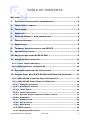
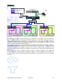
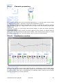
Version 1.0 October 2009 AVP4-ES100 USER’S M A NUAL AVP4-ES100 User‟s Manual AuviTran 1 TABLE OF CONTENTS WELCOME! ........................................................................................ 3 1- ELECTRICAL AND ELECTRONIC INTERFERENCES..................................... 4 2- LIMITATION OF LIABILITY .............................................................. 5 3- TRADEMARKS............................................................................... 5 4- COPYRIGHT ................................................................................. 5 5- AUVITRAN WEBSITE / MORE INFORMATION ........................................ 5 6- PACKAGE CONTAINS ...................................................................... 5 7- PRECAUTIONS.............................................................................. 6 8- TECHNICAL SPECIFICATIONS OF THE DEVICE ..................................... 6 9- MECHANICAL OUTLINES ................................................................. 7 10- ARCHITECTURES USING AVP4-ES100 .............................................. 9 11- HARDWARE MODE SELECTION ........................................................ 11 11-1- Power Output selection............................................................ 12 11-2- GPIO connector configuration .................................................. 14 12- SOFTWARE DOWNLOAD AND INSTALLATION ...................................... 16 13- GETTING START WITH AVP4-ES100 IN ES-MONITOR SOFTWARE ........ 17 13-1- AVP4-ES100 Properties Page in ES-Monitor .............................. 17 13-2- AVP4-ES100 Control Page in ES-Monitor................................... 18 13.2.1 Channels parameters ...................................................................... 19 13.2.2 Equalisation window ....................................................................... 19 13.2.3 “Link” button .................................................................................. 21 13.2.4 Master parameters .......................................................................... 21 13.2.5 Dynamic Range Compression (DRC) control .................................... 22 13.2.6 Status box ....................................................................................... 23 13.2.7 Setup window ................................................................................. 23 13.2.8 Group Control.................................................................................. 24 13.2.9 GPIO Setup ..................................................................................... 25 13.2.10 GPIO Status .................................................................................... 26 13.2.11 Paging System Control .................................................................... 27 AVP4-ES100 User‟s Manual AuviTran 2 WELCOME! Thank you for purchasing AuviTran‟s AVP4-ES100 device. We hope you will enjoy using it. AVP4-ES100 is a configurable dual 20W/8Ω or quad 10W/8Ω outputs integrated standalone EtherSound digital power amplifier. It is ideal for Public Address and Voice Alarm systems. Build-in AVP4-ES100 parametric equalizers and Dynamic Range Control (DRC) allows speaker and room correction to enhance audio quality and intelligibility in any environment. AVP4-ES100 is able to detect automatically priority announcement messages and switch on with selectable nominal value level output thanks to a smart automated software programmable trigger. Speaker fault monitoring at any time allows remote and local alerts in case of speaker failure. Standard RJ45 and Euroblock connectors are available for EtherSound links, to make installation extremely easy and fast. A set of 4 GPI and 4 GPO makes the AVP4-ES100 locally or remotely controllable. GPIO connectors are configurable to be used as standard RS232 interface or 150mW headphones output. SOFTWARE SETUP EQ GAIN EQ GAIN PIN IN RJ45 IN ETHERSOUND INTERFACE RJ45 OUT MASTER GAIN MATRIX EQ GAIN EQ GAIN DRC POWER AMPLIFIER PIN OUT POWER SUPPLY Automatic Routing and Nominal Gain for Priority Messages GPI GPO You will find herewith the necessary instructions to install your device. Please read them carefully as misuse of this device might cause serious damage to you and your environment. AVP4-ES100 User‟s Manual AuviTran 3 1- ELECTRICAL AND ELECTRONIC INTERFERENCES This device complies with Part 15 of the FCC rules. Operation is subject to the following two conditions: 1. This device may not cause harmful interference. 2. This device must accept any interference received including interference that may cause undesired operation. FCC INFORMATION (U.S.A.) 1. IMPORTANT NOTICE: DO NOT MODIFY THIS UNIT! This product, when installed as indicated in the instructions contained in this manual, meets FCC requirements. Modifications not expressly approved by Yamaha may void your authority, granted by the FCC, to use the product. 2. IMPORTANT: When connecting this product to accessories and/or another product use only high quality shielded cables. Cable/s supplied with this product MUST be used. Follow all installation instructions. Failure to follow instructions could void your FCC authorization to use this product in the USA. 3. NOTE: This product has been tested and found to comply with the limits for a Class B Digital device, pursuant to Part 15 of the FCC Rules. These limits are designed to provide reasonable protection against harmful interference in a residential environment. This equipment generates, uses and can radiate radio frequency energy and, if not installed and used according to the instructions found in the users manual, may cause interference harmful to the operation of other radio communications. Compliance with FCC regulations does not guarantee that interference will not occur in all installations. If this product is found to be the source of interference, which can be determined by turning the unit “OFF” and “ON”, please try to eliminate the problems by using one of the following measures: Relocate either this product or the device that is being affected by the interference. Utilize power outlets that are on different branch (circuit breaker or fuse) circuits or install AC line filter(s). In the case of radio or TV interference, relocate/reorient the antenna. If the antenna lead-in is 300 ohm ribbon lead, change the lead-in to co-axial type cable. If these corrective measures do not produce satisfactory results, please contact the local retailer authorized to distribute this type of product. If you cannot locate the appropriate retailer, please contact Yamaha Commercial Audio Systems, Inc., Electronic Service Division, 6600 Orangethorpe Ave, Buena Park, CA90620. The above statements apply ONLY to those products distributed by Yamaha Commercial Audio Systems, Inc. or its subsidiaries. COMPLIANCE INFORMATION STATEMENT (DECLARATION OF CONFORMITY PROCEDURE) Responsible Party : Address : Telephone : Type of Equipment : Model Name : Yamaha Commercial Audio Systems, Inc. 6600 Orangethorpe Ave., Buena Park, Calif. 90620 714-522-9011 Digital Audio Power Amplifier AVP4-ES100 This device complies with Part 15 of the FCC Rules. Operation is subject to the following conditions: 1) This device may not cause harmful interference, and 2) This device must accept any interference received including interference that may cause undesired operation. See user manual instructions if interference to radio reception is suspected. AVP4-ES100 User‟s Manual AuviTran 4 2- LIMITATION OF LIABILITY In no case and in no way, the provider of this device (AuviTran, the distributor or reseller, or any other party acting as provider) shall be liable and sued to court for damage, either direct or indirect, caused to the user of the device and which would result from an improper installation or misuse of the device. “Misuse” and “improper installation” mean installation and use not corresponding to the instructions of this manual. Please note that graphics given in this manual (drawings and schemes) are only examples and shall not be taken for a real vision of your own equipment configuration. AuviTran is constantly working on the improvement of the products. For that purpose, the products functionalities are bound to change and be upgraded without notice. Please read carefully the User‟s manual as the new functionalities will be described therein. 3- TRADEMARKS All trademarks listed in this manual are the exclusive property of their respective owners. They are respected “as is” by AuviTran. Any use of these trademarks must receive prior approval of their respective owners. For any question, please contact the trademark‟s owner directly. 4- COPYRIGHT The information in this manual is protected by copyright. Therefore, reproduction, distribution of whole or part of this manual is strictly forbidden without the prior written agreement of AuviTran. 5- AUVITRAN WEBSITE / MORE INFORMATION Please visit our website for any question of further inquiry concerning our product range. Updates will also be posted when available. http://www.AuviTran.com 6- PACKAGE CONTAINS 1 1 2 2 2 1 AVP4-ES100 device power line connector (6 pins, 5.08 mm step) network connectors (4 pins, 3.81 mm step) speaker connectors (4 pins, 3.81 mm step) GPIO connectors (6 pins, 3.81 mm step) metal hook for security sling attach AVP4-ES100 User‟s Manual AuviTran 5 7- PRECAUTIONS Do not modify or disassemble the board. The guarantee shall be null and void in that case. Do not apply excessive pressure on connectors or any other part of the board. Do not touch the metallic sharp parts (pins) of the board. This board is electrostatic sensitive; make sure you check this before touching or using it. Few parameters are internal jumpers selectable. Please carefully read referring paragraph before opening the device. In any case, always unplug the main power cord of the device, and wait few seconds that all LED are off before opening the device. 8- TECHNICAL SPECIFICATIONS General Size 145 mm x 40 mm x 202mm Power Consumption 50 Watts Power Supply 100-240V~ 50/60Hz 1.4A Max (Phase / Neutral / Earth) Storage: Temp/Humidity - 5°C to 70°C / 0% to 95% (non-condensing) Operating: Temp/Humidity 0 °C to 40°C / 5% to 90% (non-condensing) Connectors 1x6 pole Euroblock connector (pitch 5.08mm) for AC power supply; 1x4 pole double row Euroblock connector (pitch 3.81mm) for speaker output; 1x6 pole double row Euroblock Connector (pitch 3.81mm) for GPIO. 2x RJ45 connectors for network connections. 2x4 pole Euroblock connectors (pitch 3.81mm) for alternative network connections. Audio Inputs and Outputs Number of inputs Number of outputs N.A. Up to 4 channels extracted from any of the 128xEtherSound™ channels(64 upstream or 64 downstream) Audio Specifications Total Output Power Frequency response 2x20W RMS or 4x10W RMS outputs under 8 Ohms loads / 150mW Headphones output 20Hz – 20Khz @ -3dB GPIO Specifications GP In GP Out 4x Opto-isolated. +60Vdc maximum input voltage. 4x +60Vdc/1A open drain Darlington per GPO. Internal +24Vdc available (100mA max). Development and Integration Environment OS Supported ES-Monitor Development Tools Windows 32 bits Vista/XP - ready for Seven ES-Monitor enables to remotely set, control and monitor an EtherSound network and provides enhanced control pages to manage the AVP4-ES100 specific parameters. PC Telnet based development tools allowing access and control of all of the EtherSound devices devices' parameters. AVP4-ES100 User‟s Manual AuviTran 6 9- MECHANICAL OUTLINES AVP4-ES100 User‟s Manual AuviTran 7 AVP4-ES100 User‟s Manual AuviTran 8 10- ARCHITECTURES USING AVP4-ES100 Here are some typical architectures using AVP4-ES100 associated with others EtherSound products. This will show you how AVP4-ES100 can be used to answer real needs. Example #1 Background music Analog line AVA4-ES100 EtherSound over Cat5 cable Emergency microphone and messages ES Monitor (settings at the start) EtherSound over fireproof cable Cat5 without audio Switch AVP4-ES100 AVP4-ES100 AVP4-ES100 Independant loudspeakers, all adressable with specific settings (volume, channel, EQ…) Possibility to create zones Here is a typical architecture of background music diffusion in public area (waiting room, museum, supermarket …) with priority information/alert messages. AVA4-ES100 receives analog audio signal, and sends it over EtherSound. AVP4-ES100 devices are set to listen to this signal. Paging system is active, priority channel is set to be the emergency microphone channel. If a message is sent by the microphone, all AVP4-ES100 will stop playing background music, set volume to predefined nominal level, and start broadcasting priority message. When message stops, all AVP4-ES100 will restore previous volume level, and switch back to background music. AVP4-ES100 User‟s Manual AuviTran 9 Example #2 Analog line CD player for backgroud music EtherSound over Cat5 cable Cat5 without audio GPIO line PC Announcement microphone Mixing control & Remote monitoring Switch ... Lodge #1 Lodge #2 Lodge #x ... Local volume control Local volume control Local volume control This example illustrates theatre architecture. Main room is equipped with CD player for music broadcast, and a microphone. This microphone is used when manager wants to call artists in their lodge. Microphone push buttons are combined with DME inputs to choose on which EtherSound channel message will be sent. Theses channels are also used as priority channels on AVP4-ES100. Local volume control with wall-mounted push-buttons allows users to manage volume in their lodge, or even mute sound, for their own comfort. Nevertheless, if paging system detects announcement message, nominal level will be restored and message will be played. Announcement message will always be heard even if AVP4-ES100 was previously muted. Each lodge can have a specific priority channel, directly combined with DME and microphone desk, announcement message for lodge #1 will be played only in lodge #1. All other rooms won‟t be interrupted and disturbed by announcement not directly related to them. AVP4-ES100 User‟s Manual AuviTran 10 11- HARDWARE MODE SELECTION Some AVP4-ES100 functionalities are only hardware configurable. Standard jumpers are used to select appropriate function. Theses functions are divided in two groups: - Power output selection (4x10W or 2x20W) - GPIO connector configuration Power output configuration is made of two groups of three two-point pin headers. GPIO configuration is made of seven lines of three-point pin headers. You will find below a picture of the AVP4-ES100 board, to help find these pin headers. Warning: This unit contains hazardous voltages. Access to these pin headers is only possible by opening device. Please ensure that power supply source is unplugged and all LED are off before opening device. Never open the device if power supply cord is plugged. AVP4-ES100 User‟s Manual AuviTran 11 11-1- Power Output selection Schematic below helps you to precisely locate where the pins are. You can also notice that there is a space between each pair. This space avoids any confusion when trying to put the jumper on the pins. Factory default configuration is 4x10W output. Jumpers are delivered with the product, plugged only on one pin of each pin header. That way, jumpers are plugged in order to NOT short circuit the pin headers (Fig. 1). In order to set the device as 2x20W output (bridge mode), you will have to place each jumper on each pin header in order to make a short circuit (Fig. 2). Fig. 1: 4x10W output Fig. 2: 2x20W output These are the only configurations allowed. If jumpers are set in a different way than above, speakers plugged to the device may be damaged! AVP4-ES100 User‟s Manual AuviTran 12 Screen-print on the box top cover illustrates how to connect speakers for each mode (Fig. 3). When in 4x10W mode, pins [1-], [2-], [3-] and [4-] are unit ground (0 Volt). Pins [1+], [2+], [3+] and [4+] are respectively positive outputs of channel 1, 2, 3 and 4. When in 2x20W mode, pins [1-], [2-], [3-] and [4-] are left unused (but still internally connected to ground). Pin [1+] is positive output for channel 1, and [2+] is its negative output. Pin [3+] is positive output for channel 2, and [4+] is its negative output. Fig. 3: Speaker connector wiring for output mode Please note that output power is based on 8 ohms loads. 4 ohms loads are allowed, but will decrease available power. AVP4-ES100 User‟s Manual AuviTran 13 11-2- GPIO connector configuration GPIO connector is made of two lines of six pins. Each line provides four GPIO (one per pin), a ground pin (0 volt) and a +V pin (+24Vdc). Screen-print on the box top cover illustrates wiring of this connector: When configured as GPIO, all GPI are located on the top line of pins, and all GPO are on the bottom line. Inputs are opto-isolated. Amaximum voltage of +60Vdc, referring to ground („G‟ pin) is accepted. Outputs are open-drain. A maximum of +60Vdc/1A per output is accepted. O1...O4 +60Vdc/1A max I1...I4 G +60Vdc G GP Input GP Output Three out of four GPIO can be configured to have a dedicated function. This selection is made thanks to the seven lines of pin headers as previously shown. Dedicated functions are RS232 signals (Rx, Tx, RTS, CTS) and stereo headphone output. Screen-print illustrates how to set jumpers in order to choose between GPIO or dedicated function. AVP4-ES100 User‟s Manual AuviTran 14 Each configuration can be set individually. You can mix GPI, GPO and dedicated functions to fit your needs. Schematic below shows the pin headers on the board, and gives few examples of available configuration: Fig. 4 Fig. 5 Fig. 6 Fig. 4: 4 GPI, 4 GPO Fig. 5: 3 GPI, 3 GPO, Stereo headphone output Fig. 6: 2 GPI, 2 GPO, Rx/Tx + RTS/CTS RS232 signals Please note that JO4 does not exist. This means GPO4 does not have optional function. It will always be a GPO. Please note that JI4 is unused at this time, and should be left to its original position (jumper on the right, as GPI position). GPI4 will always be a GPI. AVP4-ES100 User‟s Manual AuviTran 15 12- SOFTWARE DOWNLOAD AND INSTALLATION Please visit our website to download the latest version of our EtherSound Monitor Software called ES-Monitor (http://www.auvitran.com) and save installation file on your hard disk. ES-Monitor requires Windows 2000, XP or Vista to function. You are now ready for installation. Refer to the ES-Monitor documentation for installation procedure. Once ES-Monitor installed on your PC, you can run ES-Monitor and manage any EtherSound devices connected to an EtherSound network. AVP4-ES100 is one EtherSound device with specific property and control page explained below. Refer to the ES-Monitor documentation for generic EtherSound device management such as Enumeration of EtherSound devices and I/O routing. AVP4-ES100 User‟s Manual AuviTran 16 13- GETTING START WITH AVP4-ES100 IN ES-MONITOR SOFTWARE 13-1- AVP4-ES100 Properties Page in ES-Monitor Computer where EtherSound Monitor was installed should be now connected to the primary master of the EtherSound network. The primary master is the first EtherSoundbased device of the network. After running ES-Monitor, select an AVP4-ES100 device on the device list or tree list. When selected, ES-Monitor will display the following information in the “properties” tab: This page gives you general indication on device, such as MAC address, firmware and EtherSound kernel version, number of outputs available (that is correlated with the jumper configuration), and network quality if activated. Please refer to ES-Monitor documentation for a complete description. AVP4-ES100 User‟s Manual AuviTran 17 13-2- AVP4-ES100 Control Page in ES-Monitor When control page of selected AVP4-ES100 is activated, ES-Monitor displays: Basic features are displayed when first selecting the control page. It allows user to have a quick overview and control access to the device. This interface allows user to: - See general status of the device (faulty status for instance) - See and control gain for each channel - See equalization configured on each channel, ability to turn on or off - See and control master gain - Access and turn on or off Dynamic Range Compression (DRC) - Create control pairs (“link” button) AVP4-ES100 User‟s Manual AuviTran 18 13.2.1 Channels parameters Each channel has the same set of individual parameters, i.e. accurate gain control (fader or direct numeric value), real-time vu-meter and equalisation control. The gain can be set by moving the fader up or down, or directly by typing a numeric value between 0 and -117. Using wheel mouse over gain slider also allows to adjust gain step by step. Real-time vu-meter is a post-fader and post-EQ display. It show the signal effectively sent to the speaker. Equalisation control button shows correction applied to the channel. It allows having a quick view without opening the EQ control window. “ON” button below shows if current correction is applied or not. You can directly click on it to turn on/off the EQ. 13.2.2 Equalisation window When clicking on EQ control button described above, equalisation control window popsup. Each channel has its own equalisation window. Seven parametric filters are available for each channel. Each filter is represented by a different colour, helping user to quickly identify which band is currently selected. AVP4-ES100 User‟s Manual AuviTran 19 Pre and post vu-meters (respectively on left and right) are displayed to help user tuning filter gain and global gain to the best value without clipping. A clip indicator is also available for each band, indicating in real time that the applied correction is clipping the signal. To allow use of a positive correction (gain) even if the input level is too high, a local attenuator (“ATT” button) is available. This attenuator will apply a -12dB gain to the input signal, giving enough headroom for a correction. Each band control is identical, and detailed below. Three parameters commonly available on parametric equalizers can be set, i.e. frequency (F), quality factor (Q) and gain (G). Theses parameters are displayed numerically to provide an accurate view and control of each band. Of course, direct control on the graph is possible with the mouse. When the mouse pointer is over the desired point, the colour bar of associated filter is blinking. This informs user of which band is selected, in case of two or more points were covering each other. To change correction applied, just click on the desired point, and drag it over the graph. A horizontal move will change the frequency, as a vertical move will act on the gain. To change the quality factor, just roll up or down the wheel mouse. Each band has a range of +/-18dB gain. If you want to apply a correction over this range, you should use two or more bands set on the same frequency. That way, gain of each band will be added. You can also use the Zoom “+” and “-” button to change graph scale, if needed. Clip signal indicates in real-time if signal processed by the filter is over-range. It illuminates in red when occurs. Quick configuration for high-pass and low-pass filter is also available by clicking on the button next to the clip display: - This indicates the filter is a standard parametric filter. This is the default setup. - First order high-pass filter. Default cut frequency is 100Hz. - First order low-pass filter. Default cut frequency is 19kHz. “Flat” button allows quick restore for all filters to a flat response. Be aware that this is not a bypass button. Previously set correction will be lost by clicking on the flat button. If you want to quickly listen to the signal “with and without” correction, use the “ON” button to switch equalization on or off. Fader available in this window is another access to the fader available directly on the control page. Acting on this fader will act also in real-time the fader of the control page. AVP4-ES100 User‟s Manual AuviTran 20 13.2.3 “Link” button This button, available on the basic control page, allows user to create pairs of control, as a mixing console will do. When channels are linked together, following parameters will be duplicated: - fader position (global gain value) - equalization parameters - equalization on/off status - attenuator status The link button between Output 1 and Output 2 links these two outputs. This is exactly the same for the button between Outputs 3 and 4. The link button on centre, between Output 2 and Output 3 allows linking the four channels together. When clicking on a link button, a window opens, asking the user which channel should gives its parameters to the other. Simply click again on link button to split the pair. 13.2.4 Master parameters This control acts on all four (or two, depending on the mode that is set) channels of the device. Fader for master volume is displayed in a different colour, to help you remember this is a global control. Moving this fader or typing a numeric value will affect all channels volume. Clicking DRC Setup button will open the DRC control window. Dynamic Range Compression (DRC) is a fully programmable compressor that acts on all channels at the same time. The “ON” button allows to turn it on or off (bypass) exactly as the equalization “ON” button. “COMP” status will illuminate if at least one channel signal level has reached the compressor trigger. In other words, this status indicates that audio signal is currently compressed. AVP4-ES100 User‟s Manual AuviTran 21 13.2.5 Dynamic Range Compression (DRC) control Embedded AVP4-ES100 DRC is a fully configurable Dynamic Range Compressor. User can select: - Threshold (Thr.): when at least one channel signal value reach this value, DRC will trig and start working after the “attack time” delay value. Once the signal goes below this threshold, DRC will stop working after the “release time” delay value. - Ratio: indicates the new amplifier slope (gain) when compressor is acting. A direct graph reading indicates the output signal amplitude depending of input amplitude. In this example, as soon as signal is higher than -62dB, compressor will apply a gain ratio of 0.23. When input signal will reach 0dB, output signal will only be -48dB. - Energy Time: indicates the depth of the window used to calculate the average signal. This is this average signal that is compared to the threshold. - Attack Time: indicates the time left between the trigger and the effective compression. - Release Time: indicates the time left between the end of the trigger and the effective release. “ON” button is the same as “ON” button displayed in the control page. It helps turns on/off compressor without changing the desired response. AVP4-ES100 User‟s Manual AuviTran 22 13.2.6 Status box Status box indicates in real-time AVP4-ES100 device status. Status OK means that all functionalities are working. A green LED inside the box will also light to reflect this status (see board picture in chapter 12 to helps you locate these LED). A faulty status reflects that a problem occurs with the amplifier. It can be a short circuit on its output, over-heating, or any physical damage of this kind. Audio diffusion is therefore not guaranteed when fault status is displayed. Amplifier is supposed to have auto-recovered from default when status is back to OK, as soon as it is possible. However, we encourage user to restart amplifier after a faulty status to be sure that no error remains. A distinctive red logo will also light inside the box when amplifier is faulty. 13.2.7 Setup window Clicking setup button on AVP4-ES100 control page will pop-up a new window. This setup window gives access to all advanced parameters: - Display the Paging System control box. - Configure Group parameters to create groups of AVP4-ES100 inside the network. - Configure and monitor all GPIO. AVP4-ES100 User‟s Manual AuviTran 23 13.2.8 Group Control AVP4-ES100 has an embedded function that allows building groups of devices. Devices inside a group will automatically receive all parameters from the group master (i.e. the first device of the group within the daisy-chain). Theses parameters are: - Gain of channel 1 and 2 (if selected) - Gain of channel 3 and 4 (if selected) - All paging system parameters Thanks to this stand alone feature, user can change parameters of all devices within the group by acting only on group master device control page. Also, if paging system is used, all devices will behave as the group master. This is really useful when multiples AVP4ES100 are used in the same broadcast zone. Moreover, only one external control panel plugged to AVP4-ES400 group master GPI‟s is needed to remotely control all devices within the group at the same time. PC Mixing control & Remote monitoring #1 #6 Group Master #2 #5 #3 #4 Group A Group B Group Master In this example, 6 AVP4-ES100 are used in an EtherSound network. Procedure to create group is extremely easy: - Set device #1 as Group Master by clicking on checkbox “Set Device as Group Master” - Choose which gain you want to send to the next device by checking the appropriate box. - In target combo-box, select next device of group, i.e. device #2 in this example. - Go to device #2 control page, and open setup menu - Choose which gain you want to send to the next device by checking the appropriate box. - In target combo-box, select next device of group, i.e. device #3 in this example. - Device #3 being the end of first group, group control parameters should remain unchecked (no target). AVP4-ES100 User‟s Manual AuviTran 24 To create second group, process is exactly the same. Set device #4 as group master, and chain targets until the last AVP4-ES100. Please also remember that: - Contiguous devices are not mandatory within the daisy chain to create a group. - There is no direct limitation regarding number of devices within a group. Limitation is made by network capacity to handle multiple EtherSound commands. - Group control is based on a point to point protocol. If chain is broken at one point, all devices following this point won‟t be addressed anymore. - If you try to change parameters on one device that is not group master, changes will be overwritten in the next second by group master. 13.2.9 GPIO Setup As shown in chapter 12-2, GPIO connector can be configured as GPIO or as dedicated function. GPIO setup box allows user to inform software which mode is selected for each GPI/GPO. As there is no way for software to detect jumper configuration, this procedure is needed to display right information. When GPI pins are used as Inputs (no dedicated function selected), user can remote control channel gain thanks to external push-buttons. To do so, option “Use GPI as Gain Remote Control” must be checked. How to wire and use GPI as gain remote control is described below. GPI connector 1 A 2 B 3 4 G + C D Push-buttons can be of any kind, as soon as it can handle the 24V provided by AVP4ES100. When wired like this, checking “Use GPI as Gain Remote Control” box allows you to: - Increment gain of channel 1&2 when pushing button A - Decrement gain of channel 1&2 when pushing button B - Increment gain of channel 3&4 when pushing button C - Decrement gain of channel 3&4 when pushing button D - Set gain to min. (-117dB) for channel 1&2 when pushing both A and B together - Set gain to min. (-117dB) for channel 3&4 when pushing both C and D together AVP4-ES100 User‟s Manual AuviTran 25 Option “Link Gain” makes pair [A,B] and [C,D] act for all four channels. In other words, pushing A or C will have the same effect, i.e. increment gain for all four channels. Pushing B or D will decrement gain for all four channels. Idea is the same for resetting gain to -117dB. Using GPI as gain remote control is perfect when user needs to have local control of amplifier volume inside a room, with wall-mounted push-buttons for discrete and smart integration. 13.2.10 GPIO Status This box is a real-time control/monitoring of GPIO state. When in GPI mode, each GPI displays in real-time the state of input with a dark “Off” icon, or a blue “On” icon. When in GPO mode, each GPO can be turned on or off by clicking on its respective “Set” button. If GPI/GPO are set to a dedicated function, respective icon in GPIO Status box will change to “N/A” to inform user that there is no monitoring available. AVP4-ES100 User‟s Manual AuviTran 26 13.2.11 Paging System Control AVP4-ES100 has an embedded and stand-alone paging system. This feature gives priority to selected EtherSound audio channels (one priority channel available per output). When a priority signal is detected, system stops playing the current channel, restores output gain to a defined nominal gain, and starts playing priority channel. Once priority message is over, system goes back to previously playing channel, restoring initial gain value. This system was designed for announcement messages, security alert diffusion, and every situation where some audio signals have a higher priority than all other signals. To display paging system control box, user has to check the “Display Paging System Control” in AVP4-ES100 Setup window. To access paging configuration window, click on “Config” button. This will display the following: AVP4-ES100 User‟s Manual AuviTran 27 Each AVP4-ES100 output channel has its own paging parameters, allowing highly flexible configuration. From top to bottom, you will find: - Release time: sets the time between the end of priority message, and the moment where the previous channel is restored. Available values are 1, 2, 4 and 8 seconds. - ES Channel: defines which EtherSound channel is the priority channel for this output. You can freely choose between the 64 downstream channels and the 64 upstream channels. If you do not want priority signal management, set ES Channel to “MUTE” (default value). - Trigger Level: this fader defines the level (dB value) that should reach the signal on the priority channel to trig the system. This is useful when the source of priority message is a microphone. Tuning this fader will avoid wrong trigger due to ambient noise that could be captured by the microphone. - Nominal Level: this fader sets the level (dB value) that will be applied to the channel when priority signal is played. The previous level will be restored at the end of the paging process. - “HI” button: this button sets the trigger value to “HI Sensibility”, which is maximum sensibility available (-143dBFs). System will trig as soon as signal on defined security channel is different from a digital zero. This is useful when people wants to trig just by opening a microphone, ambient noise being enough to have a non-zero signal. - “ATT” button: this button will activate the input attenuator when a priority message is played. This is the same attenuator as described in chapter 13.2.2. It avoid signal clipping if priority signal is strong, and if equalization is applied on the channel. When an output of AVP4-ES100 is currently broadcasting a priority message, this will be illustrated by an illumination of corresponding “Call” icon. Fader position will also change to reflect nominal gain value. AVP4-ES100 User‟s Manual AuviTran 28