1
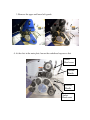
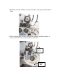
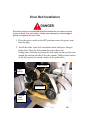
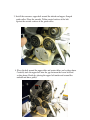
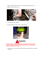
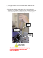
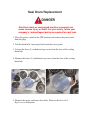
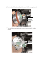
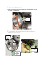
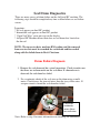
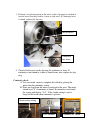
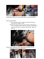
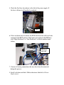
AirSpeed HC Belt Replacement and Drum
Delivery
Systems
Diagnostic
Manual
Smart Delivery System
USER MANUAL
Drive Belt Removal
1. Place the power switch in the OFF position remove the power cord
from the plug.
Electrical shock or unexpected machine movement can cause serious
injury or death. For your safety, follow your company’s lockout/tagout
policy as required for each task.
2. Lift the hood fully, lowering it back onto the cover guard.
NOTE: Additional access to the drive belts can
be achieved by removing the outfeed
cover guard with an Allen™ wrench.
3. Remove the upper and lower belt guards
4. At the slots in the main plate, loosen the sockethead capscrews that
Socket
Head screw
Tension
Handle
Tension
Handle
Socket
Head screw
5. Push the tensioner handles towards each other removing tension from the
belts.
6. First slide both belts off the sealing drum together and then continue to
remove them from the remaining idlers and rollers
Upper
Belt
Lower
Belt
Drive Belt Installation
Electrical shock or unexpected machine movement can cause serious
injury or death. For your safety, follow your company’s lockout/tagout
policy as required for each task.
1. Place the power switch in the OFF position remove the power cord
from the plug.
2. Install the wider, lower belt around the infeed end lower, flanged
guide roller. Place the belt around the center idlers and
sealing drum, finishing by placing the belt under the drive pulley and
around the outfeed end idler. Place the smooth, Teflon-coated surface
of the belt against the outside surface of the guide roller.
Center idlers
Drive
Pulley
Seal Drum
Outfeed
End
Roller
3. Install the narrower, upper belt around the infeed end upper, flanged
guide roller. Place the smooth, Teflon-coated surface of the belt
against the outside surface of the guide roller.
4. Place the belt around the upper idler and center idlers and sealing drum.
Carefully tuck the upper belt into the gap between the lower belt and
sealing drum. Finish by placing the upper belt under and around the
outfeed end drive pulley
5. Apply a slight amount of tension to each of the tension handles and
tighten the socket head screw.
.
6. Apply power to the machine.
7. Jog the machine for 30 seconds to align the belts
Electrical shock or unexpected machine movement can cause serious
injury or death. For your safety, follow your company’s lockout/tagout
policy as required for each task.
8. Place the power switch in the OFF position remove the power cord from
the plug.
9. Loosen the socket cap screw to loosen the tension on the upper and
lower belts.
10. Pull the upper tensioner handle upward with a spring scale until a
reading of 25 lbs. of force is applied to the belt. Hold the tension on the
handle while tightening the sockethead cap screw to lock it in place.
Spring
Scale
Socket
Head screw
Tension
Handle
Do not try to move the belts while jogging
or running. Exposed nip points could
injure the operator.
Seal Drum Replacement
Electrical shock or unexpected machine movement can
cause serious injury or death. For your safety, follow your
company’s lockout/tagout policy as required for each task.
1. Place the power switch in the OFF position and remove the power cord
from the plug.
2. Lift the hood fully, lowering it back onto the cover guard.
3. Loosen the three (3) sockethead cap screws from the face of the sealing
drum hub.
4. Remove the three (3) sockethead cap screws from the face of the sealing
drum hub.
5. Remove the upper and lower drive belts. Refer to the Drive Belt
Replacement instruction.
6. Grip the drum hub and carefully pull it outward off the sealing drum axle.
Electrical
connector
7. Turn the hub over and unplug the electrical connection on the inside of
the hub.
Electrical
connector
8. Secure a new replacement drum.
9. Plug the electrical connector extending from the sealing drum axle into
the inside of the drum hub.
Electrical
connector
10.Carefully tuck the wires into the hollow axle shaft as you insert the
drum onto the end of the axle.
Seal
Drum
Axle
Carefully
Tuck Wires
Hub
Mounting
Holes
11.Line up the three holes and install the three socket head cap screws
through the face of the sealing drum hub and into the mating holes in the
end of the axle. Turn cap screws in fully, but do not tighten.
12. Install the upper and lower drive belts. Refer to the Drive Belt
Replacement instruction.
NOTE: The drive belts tension is used to hold the sealing drum hub
stationary while the mounting screws are tightened.
13. Tighten the mounting cap screws in an alternating pattern so that the hub
is pulled on the axle evenly.
14. Place the power switch in the ON position and install the power cord
from the plug.
Seal Drum Diagnostics
There are many causes of drum failure on the AirSpeed HC machine. The
following steps should be completed any time a drum failure or seal failure
occurs.
Symptoms:
* No seal appears on final HC product
* Intermittent seal appears on final HC product
* “Open Seal Wire” error message on the display
* AirSpeed HC Machine blows main fuse or seal drum fuse located on
the din rail
NOTE: The in-service date, machine KM reading and the removed
from service date must be recorded for each drum and forwarded
along with the failed drum to Brett Christeon.
Drum Failure Diagnosis
1. Remove the seal drum and do a visual inspection. Check to make sure
that there are no burn marks on the seal drum. If a burned area is
observed, the seal drum has failed.
2. Do a continuity check of the seal wire on the drum using a multi
meter. Check across the two red wires then the two yellow wires. If
an open circuit is found the seal drum has failed.
Check for
continuity
across these
two red wires
Note: Refer to step 4 for more information on checking for continuity>
3. Perform a visual inspection of the wires on the slip ring for crushed or
twisted wires that may lead to a short or split wire. If a damaged wire
is found, replace the slip ring.
Twisted wires
Crushed or
bare wires
4. Check all 6 the wires in the slip ring for continuity or short. If
continuity is not found or a short is found in any wire, replace the slip
ring.
Continuity check:
A. Use your multi- meter to complete this check by placing the
meter into the continuity setting.
B. Place one lead from the meter to each end of the wire. The meter
should read “0” if continuity is found. If continuity is not found
the screen will display “O.L”. If the Audio setting is used, a
beep will be heard when continuity is present.
Correct meter setting
No Continuity
Continuity or “BEEP”
NOTE: Remove both wires from terminal and test each wire individually.
Short to ground check:
A. Use your multi- meter to complete this check by placing the
meter into the continuity setting.
B. Place the lead from the meter on the wire then touch the other
lead to the chassis of the machine. If continuity is found between
any wire and the chassis (ground) of the machine, replace the
slip ring.
NOTE: Remove both wires from terminal block and Solid State relay
terminal and test each wire individually.
4. Check the Seal fuse located just to the left of the power supply. If
the fuse is blown it will need to be replaced
Fuse
6. If the seal drum fuse has blown, the RTD feed back unit will need to be
replaced. If the RDT unit has failed and is not replaced, the HMI may
read “High Feed back” or “Low Feed back” or lead to another drum
failure.
RTD feed
back unit
7. Connect all wiring connections that may have been disconnected
during this process.
8. Install seal drum and belts. Follow directions labeled Seal Drum
Replacement.
9. Power on AirSpeed machine and test unit by running material and
checking seal integrity.