1
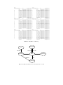
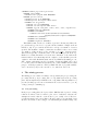
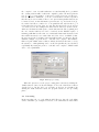
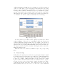
EMiT: A process mining tool
B.F. van Dongen and W.M.P. van der Aalst
Department of Technology Management, Eindhoven University of Technology
P.O. Box 513, NL-5600 MB, Eindhoven, The Netherlands.
[email protected]
Abstract. Process mining offers a way to distill process models from
event logs originating from transactional systems in logistics, banking,
e-business, health-care, etc. The algorithms used for process mining are
complex and in practise large logs are needed to derive a high-quality
process model. To support these efforts, the process mining tool EMiT
has been built. EMiT is a tool that imports event logs using a standard
XML format as input. Using an extended version of the α-algorithm
[3, 8] it can discover the underlying process model and represent it in
terms of a Petri net. This Petri net is then visualized by the program,
automatically generating a “smart” layout of the model. To support the
practical application of the tool, various adapters have been developed
that allow for the translation of system-specific logs to the standard
XML format. As a running example, we use an event log generated by
the workflow management system Staffware.
1
Introduction
During the last decade workflow management concepts and technology [2, 4, 10,
11] have been applied in many enterprise information systems. Workflow management systems such as Staffware, IBM MQSeries, COSA, etc. offer generic
modeling and enactment capabilities for structured business processes. By making graphical process definitions, i.e., models describing the life-cycle of a typical case (workflow instance) in isolation, one can configure these systems to
support business processes. Besides pure workflow management systems many
other software systems have adopted workflow technology. Consider for example
ERP (Enterprise Resource Planning) systems such as SAP, PeopleSoft, Baan
and Oracle, CRM (Customer Relationship Management) software, etc. Despite
its promise, many problems are encountered when applying workflow technology. One of the problems is that these systems require a workflow design, i.e., a
designer has to construct a detailed model accurately describing the routing of
work. Modeling a workflow is far from trivial: It requires deep knowledge of the
workflow language and lengthy discussions with the workers and management
involved.
Instead of starting with a workflow design, one could also start by gathering
information about the workflow processes as they take place. In this paper it is
assumed that it is possible to record events such that (i) each event refers to a
task (i.e., a well-defined step in the workflow), (ii) each event refers to a case
(i.e., a workflow instance), and (iii) events are totally ordered. Most information
system will offer this information in some form. Note that (transactional) systems
such as ERP, CRM, or workflow management systems indeed provide event logs.
It is also important to note that the applicability of process mining is not limited
to workflow management systems. The only requirement is that it is possible to
collect logs with event data. These event logs are used to construct a process
specification which adequately models the behavior registered.
The term process mining is used for the method of distilling a structured
process description from a set of real executions. In this paper we do not give
an overview of related work in this area. Instead we refer to the survey paper [6]
and a special issue of Computers in Industry [7].
In this paper, the process mining tool EMiT is presented. Using an example
log generated by Staffware, we illustrate the various aspects of the tool. In Section
3, the XML format used to store logs is described. Section 4 discusses the three
main steps of the mining process. Section 5 discusses the export and visualization
of the Petri nets discovered in the mining process. Finally, we conclude the paper.
2
Running example
To illustrate the functionality of EMiT, an example log generated by the Staffware
[12] is used. Since Staffware is one of the leading workflow management systems,
it is a nice illustration of the practical applicability of EMiT. For presentation
purposes we consider a log holding only six cases, as shown in Table 1.
Although the log presented here is rather small (only six cases) it is already
hard to find the structure of the underlying workflow net by just examining
the log. Therefore, a tool like EMiT is needed. However, before EMiT can be
used, the log is translated into a generic input format that is tool-independent,
i.e., EMiT does not rely on the specific format used by a system like Staffware.
Instead there is a “Staffware adapter” translating Staffware logs to the XML
format described in the next section.
3
A common XML log format
Every log file contains detailed information about the events as they take place.
However, commercial workflow system use propriety logging formats. Therefore,
EMiT uses a tool-independent XML format. Since events in the log refer to state
changes a first step is to describe the states in which each specific task can be.
For this purpose we use a transactional model.
3.1
A transactional model
To describe the state of a task the Finite State Machine (FSM) shown in Figure 1 is used. The FSM describes all possible states of a task from creation to
completion. The arrows in this figure describe all possible transitions between
states and it is assumed that these transitions are atomic events (i.e. events that
take no time) that appear in the log. All states and the transitions between those
states will be discussed below.
Case 1
Step description Event
User
yyyy/mm/dd hh:mm
--------------------------------------------------------------Start
bvdongen@staffw_ 2002/04/18 09:05
A
Processed To bvdongen@staffw_ 2002/04/18 09:05
A
Released By bvdongen@staffw_ 2002/04/18 09:05
B
Processed To bvdongen@staffw_ 2002/04/18 09:05
B
Released By bvdongen@staffw_ 2002/04/18 09:05
D
Processed To bvdongen@staffw_ 2002/04/18 09:05
E
Processed To bvdongen@staffw_ 2002/04/18 09:05
D
Released By bvdongen@staffw_ 2002/04/18 09:06
E
Released By bvdongen@staffw_ 2002/04/18 09:06
G
Processed To bvdongen@staffw_ 2002/04/18 09:06
G
Released By bvdongen@staffw_ 2002/04/18 09:06
I
Processed To bvdongen@staffw_ 2002/04/18 09:06
I
Released By bvdongen@staffw_ 2002/04/18 09:06
Terminated
2002/04/18 09:06
Case 2
Step description Event
User
yyyy/mm/dd hh:mm
--------------------------------------------------------------Start
bvdongen@staffw_ 2002/04/18 09:05
A
Processed To bvdongen@staffw_ 2002/04/18 09:05
A
Released By bvdongen@staffw_ 2002/04/18 09:05
B
Processed To bvdongen@staffw_ 2002/04/18 09:05
B
Released By bvdongen@staffw_ 2002/04/18 09:05
D
Processed To bvdongen@staffw_ 2002/04/18 09:05
E
Processed To bvdongen@staffw_ 2002/04/18 09:05
E
Released By bvdongen@staffw_ 2002/04/18 09:06
D
Released By bvdongen@staffw_ 2002/04/18 09:06
G
Processed To bvdongen@staffw_ 2002/04/18 09:06
G
Released By bvdongen@staffw_ 2002/04/18 09:06
I
Processed To bvdongen@staffw_ 2002/04/18 09:06
I
Released By bvdongen@staffw_ 2002/04/18 09:06
Terminated
2002/04/18 09:07
Case 3
Step description Event
User
yyyy/mm/dd hh:mm
--------------------------------------------------------------Start
bvdongen@staffw_ 2002/04/18 09:05
A
Processed To bvdongen@staffw_ 2002/04/18 09:05
A
Released By bvdongen@staffw_ 2002/04/18 09:05
C
Processed To bvdongen@staffw_ 2002/04/18 09:05
C
Released By bvdongen@staffw_ 2002/04/18 09:05
F
Processed To bvdongen@staffw_ 2002/04/18 09:05
E
Processed To bvdongen@staffw_ 2002/04/18 09:05
E
Released By bvdongen@staffw_ 2002/04/18 09:06
F
Released By bvdongen@staffw_ 2002/04/18 09:06
H
Processed To bvdongen@staffw_ 2002/04/18 09:06
H
Released By bvdongen@staffw_ 2002/04/18 09:06
I
Processed To bvdongen@staffw_ 2002/04/18 09:06
I
Released By bvdongen@staffw_ 2002/04/18 09:06
Terminated
2002/04/18 09:07
|
|
|
|
|
|
|
|
|
|
|
|
|
|
|
|
|
|
|
|
|
|
|
|
|
|
|
|
|
|
|
|
|
|
|
|
|
|
|
|
|
|
|
|
|
|
|
|
|
|
| Case 4
Step description Event
User
yyyy/mm/dd hh:mm
--------------------------------------------------------------Start
bvdongen@staffw_ 2002/04/18 09:05
A
Processed To bvdongen@staffw_ 2002/04/18 09:05
A
Released By bvdongen@staffw_ 2002/04/18 09:05
C
Processed To bvdongen@staffw_ 2002/04/18 09:05
C
Released By bvdongen@staffw_ 2002/04/18 09:05
F
Processed To bvdongen@staffw_ 2002/04/18 09:05
E
Processed To bvdongen@staffw_ 2002/04/18 09:05
F
Released By bvdongen@staffw_ 2002/04/18 09:06
E
Released By bvdongen@staffw_ 2002/04/18 09:06
H
Processed To bvdongen@staffw_ 2002/04/18 09:06
H
Released By bvdongen@staffw_ 2002/04/18 09:06
I
Processed To bvdongen@staffw_ 2002/04/18 09:06
I
Released By bvdongen@staffw_ 2002/04/18 09:07
Terminated
2002/04/18 09:07
Case 5
Step description Event
User
yyyy/mm/dd hh:mm
--------------------------------------------------------------Start
bvdongen@staffw_ 2002/04/18 13:47
A
Processed To bvdongen@staffw_ 2002/04/18 13:47
A
Released By bvdongen@staffw_ 2002/04/18 13:49
C
Processed To bvdongen@staffw_ 2002/04/18 13:49
C
Released By bvdongen@staffw_ 2002/04/18 13:53
F
Processed To bvdongen@staffw_ 2002/04/18 13:53
E
Processed To bvdongen@staffw_ 2002/04/18 13:53
E
Released By bvdongen@staffw_ 2002/04/18 13:56
F
Released By bvdongen@staffw_ 2002/04/18 13:57
H
Processed To bvdongen@staffw_ 2002/04/18 13:57
H
Released By bvdongen@staffw_ 2002/04/18 13:59
I
Processed To bvdongen@staffw_ 2002/04/18 13:59
I
Released By bvdongen@staffw_ 2002/04/18 14:04
Terminated
2002/04/18 09:07
Case 6
Step description Event
User
yyyy/mm/dd hh:mm
--------------------------------------------------------------Start
bvdongen@staffw_ 2002/04/18 13:48
A
Processed To bvdongen@staffw_ 2002/04/18 13:48
A
Released By bvdongen@staffw_ 2002/04/18 13:48
B
Processed To bvdongen@staffw_ 2002/04/18 13:48
B
Released By bvdongen@staffw_ 2002/04/18 13:53
D
Processed To bvdongen@staffw_ 2002/04/18 13:53
E
Processed To bvdongen@staffw_ 2002/04/18 13:53
D
Released By bvdongen@staffw_ 2002/04/18 13:56
E
Released By bvdongen@staffw_ 2002/04/18 14:10
G
Processed To bvdongen@staffw_ 2002/04/18 14:10
G
Released By bvdongen@staffw_ 2002/04/18 14:13
I
Processed To bvdongen@staffw_ 2002/04/18 14:13
I
Released By bvdongen@staffw_ 2002/04/18 14:15
Terminated
2002/04/18 14:15
Table 1. A Staffware workflow log.
Suspended
New
Schedule
Scheduled
Suspend
Start
Withdraw
Resume
Active
Complete
Complete
Abort
Terminated
Fig. 1. An FMS showing the states and transitions of a task.
– New: This is the state in which a task starts. After creation of the task this is
the initial state. From this state the task can be scheduled (i.e. it will appear
as a work-item in the worklist). In the Staffware example, this schedule event
is shown as the “processed to” line.
– Scheduled: When a task is sent to one or more users, it becomes scheduled.
After that, two things can happen. Either the task is picked up by a user who
starts working on it, or it is withdrawn from the worklist. The “start” event is
not logged by Staffware, but most other systems do, e.g., InConcert logs this
event as “TASK ACQUIRE”. Staffware logs the “withdraw” event. Again
Staffware uses a different term (“withdrawn” rather than “withdraw”).
– Active: This state describes the state of the task while a user is actually
working on it. The user is for example filling out the form that belongs
to this task. Now three things can happen. First, a task can be suspended
(for example when the user goes home at night while the work is not completely finished). Second, the task can be completed successfully and third,
the task can be aborted. In the Staffware log, only the “complete” event
appears as “Released by”. The “abort” and “suspend” events are not logged
in Staffware.
– Completed: Now the task is successfully completed.
– Suspended: When a task is suspended, the only thing that can happen is that
it becomes active again by resuming the task. Note that it is not possible for
a task to be aborted or completed from this state. Before that, it has been
resumed again.
– Terminated: Now the task is not successfully completed, but it cannot be
restarted again.
It can be seen that the Staffware example does not contain all the possible
information. For example, it cannot be shown at which moment an employee
actually started working on a task. On the other hand, the Staffware log contains
information that does not fit into our FSM. Some of that information however
can be very useful. Therefore, another kind of event is defined, namely normal.
In our example the “Start” and “Terminated” events that refer to the start and
end of a case have normal as event type.
Note that Staffware is just used as an example. For other systems, e.g., ERP
systems, CRM systems, or other workflow management systems, alternative
mappings are used. However, the resulting mapping is always made onto the
Finite State Machine described in Figure 1.
3.2
XML format
After defining the possible states of a task, a standard format for storing logs
can be defined. This format is described by the following DTD:1
1
The DTD describes the current format of EMiT. A new and extended format specified in terms of an XML schema has been defined. Future generations of EMiT will
be based on this format. See http://www.processmining.org for more details.
<!ELEMENT WorkFlow_log (source?,process+)>
<!ELEMENT source EMPTY>
<!ATTLIST source program CDATA #REQUIRED>
<!ELEMENT process (case*)>
<!ATTLIST process id ID #REQUIRED>
<!ATTLIST process description CDATA "none">
<!ELEMENT case (log_line*)>
<!ATTLIST case id ID #REQUIRED>
<!ATTLIST case description CDATA "none">
<!ELEMENT log_line (task_name, event?, date?, time?, originator?)>
<!ELEMENT task_name (#PCDATA)>
<!ELEMENT event EMPTY>
<!ATTLIST event kind (normal|schedule|start|withdraw|
suspend|resume|abort|complete) #REQUIRED>
<!ELEMENT date (#PCDATA)>
<!ELEMENT time (#PCDATA)>
<!ELEMENT originator (#PCDATA)>
This XML format describes a workflow log in the following way. First, the
process that is logged needs to be specified. In the Staffware example as shown
in Table 1 only one process is shown. Then, for each process a number of cases is
specified. The Staffware example contains six cases. Each of these cases consist
of a number of lines in the log. For each line, a “log line” element is used.
This element typically contains the name of the task that is present in the log.
Further, it contains information about the state transition of the task in the
transactional model, a timestamp and the originator of the task. Except for the
originator of the task, all this information is used by EMiT in the mining process.
(The originator information is added for future extensions.) EMiT can be used
to convert log files from different systems into the common XML format. For this
purpose, external programs are called by EMiT. The list of programs available
can be extended by anyone who uses the tool to suit their own needs.
4
The mining process
The mining process consists of a number of steps, namely the pre-processing, the
processing and the post-processing. The core algorithm used in the processing
phase that is implemented in EMiT is the α-algorithm. This algorithm is not
presented in this paper. For more information the reader is referred to [3, 8, 14]
or http://www.processmining.org.
4.1
Pre-processing
In the pre-processing phase, the log is read into EMiT and the log based ordering
relations are inferred based on that log. In order to build these relations, the
assumption is made that the events in the log are totally ordered. However,
several refinements can be made. First of all, it is possible to specify which events
should be used in the rediscovering process. When using the default settings, only
the “complete” event of a task is taken into account. Basically, the log on which
the ordering relations will be built is the original log where all entries (element
type “log line”) corresponding to event types not selected are removed. However,
if a case contains a “withdraw” or “abort” event and that event is not specified
then the whole case is excluded. The second option is that parallel relations can
be inferred based on time-information present in the log. As described in [8],
two tasks A and B are considered to be in parallel if and only if in the log, A
is directly followed by B at least once and B is directly followed by A at least
once. However, here the assumption is made that A and B are atomic actions,
while in real situations tasks span a certain time interval. The beginning and
the end of such a task however can be considered atomic. EMiT is capable of
inferring parallelism for all events of a certain task, if first task A is started and
then task B is started before task A has ended. In order to let EMiT do this,
the user can give the boundaries of the intervals in terms of event types. For the
Staffware example, one profile is set to “schedule” and “complete”. For Staffware
this is a logical definition since tasks are always scheduled in the same order by
the system, i.e., although things can be executed in parallel, they are scheduled
sequentially. By setting the profile to “schedule” and “complete”, EMiT is still
able to detect parallelism.
Fig. 2. EMiT pre-processing.
When all options are set, the pre-processing phase can start by clicking the
“Build relations” button as shown in Figure 2. Now, the relations are built as
described above, but also the loops of length one and two are identified. By
clicking the “Edit relations” button, the program advances to the processing
phase.
4.2
Processing
In the next phase, the core α-algorithm is called. However, since the α-algorithm
cannot deal with loops of length one and two, some refinements are made. First
of all, all tasks that are identified as a loop of length one (cf. [3, 8]) are taken out
of the set of tasks. These loops are then plugged back in later in the processing
phase. Second, for all tasks that are identified as loops of length two, the relations
are changed. If two tasks are identified as being a loop of length two together,
say task A and task B, then a parallel relation between the two exists, AkB.
This relation is removed and two new relations are added in the following way:
A → B and B → A. More about these refinements can be found in [1].
Fig. 3. EMiT processing.
To build a Petri net, the “Make Petri net (alpha)” button should be clicked
as shown in Figure 3. Now, the core α-algorithm is called and a Petri net is
constructed. When the Petri net is built, the loops of length one are added to it
and the result is automatically exported to the dot format. This format serves
as input for the dot program [9] that will visualize the Petri net in a smart way.
The output created by dot is loaded back into EMiT again and the result of the
mining algorithm is shown.
When the Petri net is constructed, EMiT is ready for the post-processing
phase.
4.3
Post-processing
In this phase, the original log is loaded into the program again. Using the original
log and the Petri net generated in the processing step, additional information
can be derived. Besides, the relations inferred in the pre-processing phase can
be altered. To calculate additional information for the Petri net, the original
log is used. Since the Petri net that is rediscovered should be able to generate
the same log traces as were given as input, a simple algorithm is used. First,
a token is placed in the source place of the Petri net. Now, for one case, the
tasks appearing in the log are fired one by one. Of course, only the tasks that
are actually used in the pre-processing are taken into account. Every time a
token enters a place by firing a transition, a timestamp is logged for this token.
When the token is consumed again, timing information is added to the place.
This timing information consist of three parts. First, there is the waiting time.
This is the time a token has spent in a place while the transition consuming the
token was enabled. Second, there is the synchronization time. This is the time
a token spent in a place while the transition consuming the token was not yet
enabled. This typically happens if that transition needs multiple tokens to fire.
Finally there is the sojourn time, which is the sum of the two. An example of
these times for the place connecting D-complete with G-schedule can be found
in the lower right part of Figure 3.
This process is repeated for all cases. If everything goes well, then a message
is given and the picture showing the Petri net is updated. This update is done
to show the probabilities for each choice in the Petri net. If a place has multiple
outgoing arcs, a choice has to be made. The probability that each arc is chosen
is basically the number of occurrences of the transition on that arc in the log
divided by the sum of all occurrences of all transitions with an incoming arc
from that place. The timing information for each place can be made visible in
the lower right corner of the window by just clicking on a specific place in the
picture. Some metrics for the waiting time, the synchronization time and the
sojourn time are shown.
If, when replaying the original log, a transition is unable to fire, a message
is generated stating the name of the transition. Such a message is only given
for the first error. The second error message that can be generated is that after
completing a case there are still tokens remaining in the net. In order to solve
problems generated by the program, it is possible to change the set of ordering
relations that are inferred in the pre-processing phase. By clicking on a transition
in the Petri net, all relations involving that transition will be shown (except the
# relation, which represents the fact that two tasks have no causal or parallel
relation). These relations can then be altered.
5
Exporting the Petri net
After the Petri net has been rediscovered, it can be exported. By clicking the
“Export Petri net” button the Petri net is saved in three different formats. Each
format is saved in a separate file(s):
– low detail dot: This output format is used to export only the basic Petri net
with probabilities added to all arcs (if available). No timing information
will be shown in this output file. Together with the dot file, a number of
HTML files are created. These files can be used together with the dot “jpg”
and “imap” export to make a web page. Each of these HTML files contain
timing information for a specific place.
– high detail dot: This output format is used to export the basic Petri net with
probabilities added to all arc (if available) and timing information.
– Woflan: This output format can be imported by Woflan for further analysis
[13]. Woflan supports verification of the discovered model.
Fig. 4. EMiT post-processing.
After exporting the discovered model in various formats, some options for dot
can be set. The “P-net orientation” setting specifies whether the Petri net should
be draw from left to right or from top to bottom. The “Page size” setting can
be set to “A4” or “Letter”. If these options are set, dot can be used to create
pictures and other exports. The buttons “Make jpg/map” and “Make ps/jpg”
can be used to generate the graphics files. This way EMiT provides several ways
to visualize the mining result.
6
Conclusion
In this paper EMiT is presented as a tool to mine process models from timed
logs. The whole conversion process from a log file in some unspecified format
towards a Petri net representation of a process model is described in a number
of different steps. Along the way, an example is used to illustrate the use of
the tool. We invite the reader to use the tool. The tool is available for download from http://www.processmining.org. This download includes some 30 examples, both artificial and practical. The example presented in this paper is
called “sw ex 14.log” and it is converted into “sw ex 14.xml”. Both files are
included in the download.
In the future we plan to extend the tool in various ways. First of all, we
plan to enhance the mining algorithm to be able to deal with complex process
patterns, invisible/duplicate tasks, noise, etc. [1]. Second, we are developing additional adaptors to extract information from more real-life systems (e.g., SAP
and FLOWer). Third, we are working on embedding parts of the system in the
ARIS Process Performance Monitoring (PPM) tool and exporting the result to
BPR tools like Protos. We are extending the scope of the mining process to
include organizational data, data flow, social network analysis, etc. Last but
not least, we are merging the tools EMiT, Thumb [14], and MinSoN [5] into an
integrated tool.
References
1. A.K.A. de Medeiros and W.M.P. van der Aalst and A.J.M.M. Weijters. Workflow
Mining: Current Status and Future Directions. In R. Meersman, Z. Tari, and D.C.
Schmidt, editors, On The Move to Meaningful Internet Systems 2003: CoopIS,
DOA, and ODBASE, volume 2888 of Lecture Notes in Computer Science, pages
389–406. Springer-Verlag, Berlin, 2003.
2. W.M.P. van der Aalst, J. Desel, and A. Oberweis, editors. Business Process Management: Models, Techniques, and Empirical Studies, volume 1806 of Lecture Notes
in Computer Science. Springer-Verlag, Berlin, 2000.
3. W.M.P. van der Aalst and B.F. van Dongen. Discovering Workflow Performance
Models from Timed Logs. In Y. Han, S. Tai, and D. Wikarski, editors, International
Conference on Engineering and Deployment of Cooperative Information Systems
(EDCIS 2002), volume 2480 of Lecture Notes in Computer Science, pages 45–63.
Springer-Verlag, Berlin, 2002.
4. W.M.P. van der Aalst and K.M. van Hee. Workflow Management: Models, Methods,
and Systems. MIT press, Cambridge, MA, 2002.
5. W.M.P. van der Aalst and M. Song. Mining Social Networks: Uncovering interaction patterns in business processes. In M. Weske, B. Pernici, and J. Desel, editors,
International Conference on Business Process Management (BPM 2004), Lecture
Notes in Computer Science, Springer-Verlag, Berlin, 2004.
6. W.M.P. van der Aalst, B.F. van Dongen, J. Herbst, L. Maruster, G. Schimm, and
A.J.M.M. Weijters. Workflow Mining: A Survey of Issues and Approaches. Data
and Knowledge Engineering, 47(2):237–267, 2003.
7. W.M.P. van der Aalst and A.J.M.M. Weijters, editors. Process Mining, Special
Issue of Computers in Industry, Volume 53, Number 3. Elsevier Science Publishers,
Amsterdam, 2004.
8. W.M.P. van der Aalst, A.J.M.M. Weijters, and L. Maruster. Workflow Mining: Discovering Process Models from Event Logs. QUT Technical report, FIT-TR-2003-03,
Queensland University of Technology, Brisbane, 2003. (Accepted for publication
in IEEE Transactions on Knowledge and Data Engineering.).
9. AT&T. Graphviz - Open Source Graph Drawing Software (including DOT).
http://www.research.att.com/sw/tools/graphviz/.
10. S. Jablonski and C. Bussler. Workflow Management: Modeling Concepts, Architecture, and Implementation. International Thomson Computer Press, London, UK,
1996.
11. F. Leymann and D. Roller. Production Workflow: Concepts and Techniques.
Prentice-Hall PTR, Upper Saddle River, New Jersey, USA, 1999.
12. Staffware. Staffware 2000 / GWD User Manual. Staffware plc, Berkshire, United
Kingdom, 2000.
13. H.M.W. Verbeek, T. Basten, and W.M.P. van der Aalst. Diagnosing Workflow
Processes using Woflan. The Computer Journal, 44(4):246–279, 2001.
14. A.J.M.M. Weijters and W.M.P. van der Aalst. Rediscovering Workflow Models
from Event-Based Data using Little Thumb. Integrated Computer-Aided Engineering, 10(2):151–162, 2003.