1
FDS-318
User Manual
1
V 2.1
JMK
21st December 1999
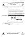
This equipment has been tested and found to comply with the following European and
international Standards for Electromagnetic Compatibility and Electrical Safety:
Radiated Emissions (EU):
RF Immunity (EU):
Mains Disturbance (EU):
Electrical Safety (EU):
Radiated Emissions (USA):
Electrical Safety (USA):
Electrical Safety (CAN):
EN55013
(1990)
EN50082/1
(1992)
EN61000/3/2
(1995)
EN60065
(1993)
FCC part 15 Class B
UL813/ETL
(1996)
UL813/ETLc
(1996)
Associated Equipment
RF Immunity, Fast Transients ESD
Commercial Audio Equipment
Commercial Audio Equipment
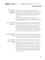
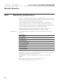
IMPORTANT SAFETY INFORMATION
DO NOT REMOVE COVERS. NO USER SERVICEABLE PARTS INSIDE, REFER SERVICING TO QUALIFIED
SERVICE PERSONNEL. THIS EQUIPMENT MUST BE EARTHED.
IT SHOULD NOT BE NECESSARY TO REMOVE ANY PROTECTIVE EARTH OR SIGNAL CABLE SHIELD
CONNECTIONS TO PREVENT GROUND LOOPS. ANY SUCH DISCONNECTIONS ARE OUTSIDE THE
RECOMMENDED PRACTICE OF BSS AUDIO AND WILL RENDER ANY EMC OR SAFETY CERTIFICATION
VOID.
For continued compliance with international EMC legislation ensure that all input and output cables are wired
with the cable screen connected to Pin 1 of the XLR connectors and/or the jack plug sleeve. The input XLR Pin 1
and the side-chain input jack socket sleeve are connected to the chassis via a low value capacitor, providing
high immunity from ground loops whilst ensuring good EMC performance.
Please read
We have written this manual with the aim of helping installers, sound engineers and musicians alike to get the
most out of the FDS-318. We recommend that you read this manual, particularly the section on installation,
before attempting to operate the unit.
The manual is split into two main sections. The first deals with quick reference information, regarding the
functions and operation of the unit, while the second covers a more general background to use and application
of the FDS-318.
We welcome any comments or questions regarding the FDS-318 or other BSS products, and you may contact us
at the address or World Wide Web site given in the warranty section.
2
Contents
Contents
1.0
What is a Crossover?
2.0
The difference between Active and
Passive Crossovers
6
3.0
Other advantages
7
4.0
The Linkwitz-Riley advantage
8
5.0
What is special about BSS
Crossovers?
9
6.0
Unpacking
9
7.0
Mechanical Installation
12
8.0
8.1
8.2
8.3
8.4
Mains Power Connection
Mains Power
Voltage Setting
AC Power Fusing
Powering up
13
13
13
14
14
9.1
9.2
9.3
9.4
Audio Connections
Wiring convention
Balanced wiring
Unbalanced wiring
Ground loop control
15
15
15
15
16
Controls and connections
Crossover frequency adjustment
control
Output level control
Polarity reverse switch
Mute switch
Signal level indicators
Select mode LED
Rear panel switch LEDs
Mains power fuse
Main power switch
17
9.0
10.0
10.1
10.2
10.3
10.4
10.5
10.6
10.7
10.8
10.9
5
17
17
17
17
18
18
18
18
19
3
Contents
10.10
10.11
10.12
10.13
10.14
10.15
Voltage selector switch
Output connections
Input connections
MONO LOW switch
CD EQ switch
SELECT MODE switch
19
19
19
20
20
20
11.0
11.1
11.2
11.3
11.4
11.5
11.6
11.7
11.8
Using the FDS-318
Selecting modes
Crossover frequency adjustment
Output level alignment
Output MUTE selector
Output polarity reverse selector
Output signal level indicators
CD Horn equalisation selector
MONO LO selector
22
22
25
25
25
25
26
26
26
12.0
12.1
12.2
Service Section
Chassis/0V Removal
Transient Suppressor Replacement
27
27
28
13.0
Specifications
29
14.0
Warranty Information
30
Index
User Notes
Spare Parts Information
4
Crossovers
1.0
What is a Crossover?
Crossovers are a necessary part of sound reinforcement systems because the
loudspeaker drive-unit which can produce clear reliable high SPL (sound
levels) over the full audio bandwidth has yet to be invented. All real-world
drive units work best when they are driven over a limited band of frequencies,
for example: Low, Mid and High.
Any crossover aims to provide the division of the audio band necessary, so
each drive unit receives only the frequencies it is designed to handle. In a high
power, high performance sound system, the crossover should also reject
unsuitable frequencies to avoid damage and poor quality sound.
Fig 1.1 Stereo 2-way
Crossover set-up
Fig 1.2 Mono 3-way
Crossover set-up
5
Active and Passive Crossovers
2.0
The difference between Active and
Passive Crossovers
Passive crossovers divide the frequency spectrum after the signal has been
raised to a high power level. They are generally heavy, bulky and inefficient.
Active crossovers utilise ICs and transistors, and divide the frequency spectrum
at line levels immediately ahead of the amplifiers (See Figure 2.1). An active
crossover does the same job as a passive crossover, but with more precision,
flexibility, efficiency, and quality.
Fig 2.1
Some advantages of active crossovers are:
• Crossover frequencies can be more readily altered to suit different driverhorn combinations.
• The level balance between the 2 or 3 frequency bands (brought on by
differences in driver and amplifier sensitivity) can be readily trimmed.
• Inside an active crossover unit, line-driving, signal summing, driver
equalisation, system muting and polarity ('phase') reversal facilities can all be
incorporated at small extra cost.
6
Crossover advantages
3.0
Other advantages
The drive-units in sound reinforcement systems utilising active crossovers
benefit because:
• Steep rolloffs are readily attainable. The -24dB/OCT rolloff in the BSS FDS318 active crossover rapidly discharges out-of-band energy. At one octave
below the crossover point, power received by the driver has dropped to less
than ½% (or 1/200th) of full power. The result: Bad sound resulting from outof-band resonances is effectively masked immediately beyond the crossover
frequency (See Figure 3.1). This contrasts markedly with passive crossovers,
where slopes in excess of -12dB/OCT are rarely achieved, and power rolloff is
4 times less rapid per octave.
Fig 3.1 Crossover
Terminology
• If one frequency range is driven into clip, drive-units and horns in other
frequency ranges are protected from damage, and distortion is kept to a
minimum.
• Direct connection of drive-units to the power amplifier cut out loss of
damping factor, normally inevitable, thanks to the appreciable resistance of the
inductors in passive crossovers.
Amplifiers benefit too from the use of active crossovers. As they do not handle
a full-range signal, clipping produces far less harmonic and intermodulation
distortion. The results: Momentary overdrive sounds less harsh. Also the
amplifiers' dynamic headroom is generally higher, and heatsink temperatures
can run lower.
7
Linkwitz-Riley Alignment
4.0
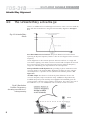
The Linkwitz-Riley advantage
There is an additional set of advantages exclusive to active crossovers made by
BSS, and other manufactures using the Linkwitz-Riley alignment (See Figure
4.1).
Fig 4.1 Linkwitz-Riley
filters
Zero Phase difference at crossover: The phase difference between drivers
operating in adjacent frequency bands is close to zero degrees at the crossover
frequency.
'Phase alignment' in this manner prevents interactive effects (i.e.: High and
Low drivers 'fighting' each other) over the narrow band of frequencies around
the crossover point, which is where the units from two adjacent frequency
ranges are contributing near equal amounts of sound pressure.
More predictable sound dispersion: By providing in-phase summation at the
crossover point(s), the Linkwitz-Riley alignment provides for more coherent
sound dispersion - it provides on-axis symmetrical radiation patterns. (See
Figure 4.2).
'Invisible' slopes: The absence of electrical phase difference close to the
crossover frequency helps to make the steep -24dB/OCT slope effectively
inaudible. Response peaks and dips are negligible and inaudible given the
correct polarity ('phasing') of the speaker connections. The same is not true of
the shallower (-6, -12 or -18dB/OCT) rates or rolloff, in other crossovers.
Fig 4.2 Radiation
Pattern Frequency
showing excellent onaxis symmetry
8
BSS Crossovers
Unpacking
5.0
What is special about BSS Crossovers?
The FDS-318 is an electronic crossover offering many modes of operation to
suit professional sound systems, and also to support equipment rental
companies in reducing crossover inventory by having an easily re-configurable
loudspeaker system controller.
The FDS-318 fully supports stereo 3-way, stereo 4-way, or four separate
channels of 2-way operation, all in a 1U package. The internal switching of
circuitry is automatically controlled by information held within a digital PROM
memory device, such that the operator needs no additional knowledge other
than the mode the currently required. As with other BSS crossover products,
output sections not used within a given configuration are always available as
full range buffer drivers. An important part of any electronic crossover is the
filter type, and todays industry standard series Butterworth filters, pioneered by
BSS Audio since 1979, is available in the FDS-318 in the form of the fourth
order Linkwitz-Riley design. These provide the necessary in-phase outputs and
steep 24dB/Oct slopes required to give the best constant voltage summation
and minimal lobing for non-coincidental drivers. These filters are fully
sweepable by accurate front panel controls, which are also automatically
reconfigured depedant upon the mode of operation selected.
Some of the features available within the FDS-318 are:
• Stereo 4-way, stereo 3-way, four channels of 2-way in a 1U unit.
• Linkwitz-Riley fourth order filters with sweepable frequency selection.
• Digitally controlled mode selection, offering extended range selection and
features.
• Electronically balanced inputs and floating balanced outputs.
• Constant directivity equalisation externally selectable for all HIGH outputs.
• Polarity reverse, mute selection and signal LED indication for each output.
• MONO LOW selection for all stereo modes.
• Comprehensive mode selection indication, identifying the function of each
control.
• Full range buffer outputs on all non-used section.
6.0
Unpacking
As part of BSS' system of quality control, this product is carefully inspected
before packing to ensure flawless appearance.
After unpacking the unit, please inspect for any physical damage and retain the
shipping carton and ALL relevant packing materials for use should the unit
need returning.
In the event that damage has occurred, please notify your dealer immediately,
so that a written claim to cover the damages can be initiated. See Section 14.
9
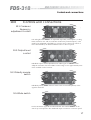
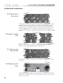
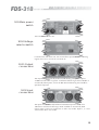
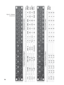
Getting to know the FDS-318
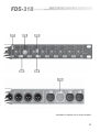
Fig 6.1 Front Panel
Fig 6.2 Rear Panel
10
All numbers in bubbles refer to Section numbers.
11
Installation
7.0
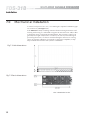
Mechanical Installation
A vertical rack space of 1U (1¾" / 44.5 mm high) is required. Ventilation gaps
are unnecessary (See Figure 7.1).
If the FDS-318 is likely to undergo extreme vibration through extensive road
trucking and touring, it is advisable to support the unit at the rear and/or sides
to lessen the stress on the front mounting flange. The necessary support can
generally be bought ready-built as a rack tray. As with any low-level signal
processing electronics, it is best to avoid mounting the unit next to a strong
source of magnetic radiation, for example, a high power amplifier, to help
keep residual noise levels in the system to a minimum.
Fig 7.1 Unit dimensions
Fig 7.2 Rack dimensions
12
Connecting to Power
8.0
Mains Power Connection
8.1 Mains Power
WARNING! THIS APPLIANCE MUST BE EARTHED.
IMPORTANT: The wires in the mains lead are colour coded in accordance
with the following code.
Green and Yellow......Earth
Blue......Neutral
Brown......Live
As the colours of the wires in the mains lead may not correspond with the
markings identifying the terminals in your plug, proceed as follows.
The wire which is coloured Green and Yellow or Green must be connected
to the terminal which is marked with the letter ‘E’ or by the Earth signal
or which is coloured Green and Yellow or Green.
The wire which is coloured Blue must be connected to the terminal labelled
‘N’ or coloured Black or Blue.
The wire which is coloured Brown must be connected to the terminal
labelled ‘L’ or coloured Red or Brown.
Those units supplied to the North American market will have an integral
moulded 3 pin connector which is provided to satisfy required local standards.
The FDS-318 must always be connected to a 3-wire grounded ('earthed') AC
outlet. The rack framework is assumed to be connected to the same grounding
circuit. The unit must NOT be operated unless the power cable's ground
('earth') wire is properly terminated - it is important for personal safety as well
as for proper control over the system grounding. To 'lift' the signal ground (0V),
refer to section 12.1.
8.2 Voltage Setting
The mains voltage selector switch (located on the side of the unit) provides a
simple external adjustment to allow operation on all international AC power
standards. The allowable ranges for the supply voltage are:
96VAC up to 132VAC on the 115V position and
192VAC up to 264VAC on the 230V position.
Outside these ranges the unit will not work satisfactorily, if at all. Voltages in
excess of the maximum will probably cause damage. Voltages below the
minimum will cause the power supplies to drop out of regulation, degrading
the performance of the system.
13
Connecting to power
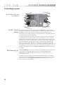
Fig 8.1 Mains fuse on
rear panel.
8.3 AC Power
Fusing
The incoming mains power is fused within the FDS-318 by the fuse holder
mounted on the rear panel (See figure 8.1). If it needs to be replaced it should
be properly rated as: 20mm 250V, T200mA for 240V voltage setting or
T250mA for 120V voltage setting. It is most important for continued safety that
this specification is strictly adhered to.
It is very unlikely that a fuse will blow during normal operation, and must be
treated with some caution as to the cause if it should do so. One of the most
likely reasons will be due to the incorrect setting of the voltage selector switch.
Another reason can be the inadvertent connection of line to line, rather than
line to neutral phase voltages when using a 3-phase power connection. In
either case, the transient suppressors can become damaged and constantly
blow replacement fuses. You can rest assured that your unit has been protected
from damage, but the transient suppressors will need to be replaced as soon as
possible for continued protection. Refer to section 12.2 for information on this
procedure.
8.4 Powering up
When the FDS-318 is switched on with the power on/off switch (located on the
rear panel), the frontpanel LEDs showing the selected MODE will be
illuminated. This indicated that the internal power supply circuitry is
functioning correctly.
Should an incorrect sequence of MODE LEDs be illuminated, or the output
signal LEDs become illuminated with no input signal present, then an internal
DC fuse may have failed. Refer to section 12.3 for information on how to
check the unit for this problem.
14
Audio connections
9.0
Audio Connections
9.1 Wiring
convention
The FDS-318 audio inputs are RFI filtered and electronically balanced, with the
outputs electronically balanced and floating. They are designed to operate at
any signal level up to +20dBu and will drive into loads of 600 ohms or greater.
Refer to figure 9.1 for the wiring convention.
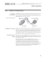
Fig 9.1 XLR Plug Wiring
9.2 Balanced wiring
Whether your system is wired to a 'Pin 2 hot' or a 'Pin 3 hot' convention is not
important, so long as the wiring to both input and output 3 pin XLR connectors
is the same. As is common with all other BSS Audio equipment of this type, we
follow the convention of 'ground goes forward with the signal'. Input cabling
screening therefore needs to be derived from the signal source end as Pin 1 is
ground lifted for the inputs. It is recommended that you use high quality audio
cable with 2 cores and a screen for low noise and reliability.
9.3 Unbalanced
wiring
If the equipment driving the FDS-318 has only unbalanced outputs, then you
will need to add a wire jumper such that the screen connection on Pin 1 of the
XLR is shorted to either Pin 2 OR Pin 3, depending on the wiring convention of
the unbalanced equipment.
If the equipment being connected to the FDS-318 outputs have only
unbalanced inputs, then we recommend that you still use a balanced (I.e.: 2
core shielded) cable. The interconnecting cable should have its screen
grounded by Pin 1 of the FDS-318 output, and Pin 3 output should be
connected to the unbalanced input 0V ground. The Pin 2 output should be
connected to the live input. There should be no connection between the cable
screen and 0V/chassis ground connection of the unbalanced equipment. Strict
adherence to this will help to eliminate potential ground loop hums by
removing signal currents from the cable screen.
15
Audio connections
9.4 Ground loop
control
Strict adherence to the wiring conventions noted above within a fully balanced
signal system will give the best possible results with none of the problems
normally associated with interconnected audio equipment. Wherever possible,
cable screens should not be connected to any signal pin, but rather left to
perform a cable shielding function only.
Where it is not possible to control all of the external cabling, it might become
necessary to have internal electronic ground of your unit separated from the
case safety ground. Provision is made internally within the FDS-318 to separate
these two grounds at a convenient point, and reference to section 12.1 will
explain the procedure.
Under no circumstances should the safety ground wire be removed from the
mains AC power connector as an interim measure to achieve similar results.
16
Controls and connections
10.0
Controls and connections
10.1 Crossover
frequency
adjustment control
Left and right hand channels are adjustable separately. The frequency scaling
LEDs, marked as x10 and /10, indicates whether the printed frequency scale
needs to be multiplied or divided by 10 for the correct value. The control of
this is determined by the SELECT MODE switch on the rear panel.
10.2 Output level
control
Individual output control adjustable from -6dB of gain to OFF. To ensure
adequate resolution, the first 12dB of control range covers approximately 60%
of the available control rotation.
10.3 Polarity reverse
switch
Individual polarity reverse selector switch. Push to invert the polarity of the
signal in that band.
10.4 Mute switch
Push to MUTE the signal in the selected band. The number marked on the
switch cap corresponds to the numbered output connectors on the rear panel.
17
Controls and connections
10.5 Signal level
indicators
The SIG LED indicated that a signal is being received within that band, and the
PEAK LED warns of the possible onset of system overload. The SIG LED will
not light for signals below peak level of -20dB, and the PEAK LED lights for
signals in excess of +10dB. This does not represent the maximum signal level
within the FDS-318 (which is +20dBv), but rather that the sound system is
being driven very hard. For a more detailed explanation of this, refer to section
11.6.
10.6 Select mode
LED
These LEDs show which mode of operation has been selected by the rear panel
SELECT MODE switch. They also point toward the correct control knob
function, as this varied dependant on the mode selected.
10.7 Rear panel
switch LEDs
These LEDs show the status of the CD EQ and MONO LOW switches on the
rear panel.
10.8 Mains power
fuse
The mains power fuse is 20mm long, and rated T250mA for 120V settings and
T200mA for 240V settings. For continued protection, ALWAYS replace this fuse
with the correct value.
18
10.9 Main power
switch
Turns the FDS-318 on or off.
10.10 Voltage
selector switch
Located on the side of the unit, this switch allows operation in the following
regions: 96-132V or 192-264V, 50-60Hz AC.
10.11 Output
connections
The outputs are electronically balanced and floating. Maximum output is
+20dBu into 600 ohms or greater. Transformer balancing is NOT available as
an internally fitted option, and so the BSS AR-204 balancing unit should be
specified if required.
10.12 Input
connections
The inputs are electronically balanced. Maximum input is +20dBu in to
10Kohms. Transformer balancing is NOT available is an internally fitted
option. Inputs 1 and 2 are used for the 4- and 3-way modes. Inputs 1, 2, 3 and
4 are used for the 2-way modes.
19
Controls and connections
10.13 MONO LOW
switch
The MONO LOW switch operates in all stereo modes of operation and
actively sums the signal information together on the LOW outputs. Both left
and right LOW outputs will then contain the summed LOW signal.
10.14 CD EQ switch
The CD EQ switch inserts constant directivity equalisation on all relevant
outputs, dependant on the mode selected. Refer to the table in section 11.1 for
more information.
10.15 SELECT MODE
switch
The FDS-318 is designed to offer seven different modes of operation:
4-way:
4-way HF:
Two channels of 3 non overlapping frequency bands with
an extra high pass parallel band running at a different
selectable frequency. This allows a sound system to utilise
two different high frequency horn drivers which require a
different crossover frequency.
4-way LF:
Two channels of 3 non overlapping frequency bands
with an extra low pass parallel band running at a different
selectable frequency. This allows a 3-way sound system to
operate with an optional sub bass system.
3-way:
2-way HI:
20
Two channels of 4 non overlapping frequency modes.
Two channels of 3 non overlapping frequency bands. The
unused upper control configured to operate as full range
output buffers.
Four channels of 2 non overlapping frequency bands with
the frequency control configured to operate over a 2kHz to
20kHz sweep range.
2-way MID:
2-way LO:
Four channels of 2 non overlapping frequency bands with
the frequency control configured to operate over a 200Hz
to 2kHz sweep range.
Four channels of 2 non overlapping frequency bands with
the frequency control configured to operate over a 20Hz to
200Hz sweep range.
21
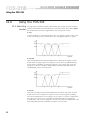
Using the FDS-318
11.0
Using the FDS-318
11.1 Selecting
modes
The appropriate mode should be selected with the rear panel switch, and this
will be confirmed by the LED indicators on the front panel. The table in figure
11.1 indicates the functions applicable to each front panel control.
4-way:
Use this mode for a conventional stereo four way speaker system, where each
of the four bands operate over different, non overlapping frequency ranges.
4-way HP:
Here the HI PASS front panel LED illuminates to indicate the mode. Use this
mode when two high outputs are required, such as when an additional long
throw driver is needed to augment an existing 3-way system. The crossover
frequency of the extra output is independent, and fully adjustable from the
standard high output crossover point.
4-way LP:
Here the LO PASS front panel LED illuminates to indicate the mode. Use this
mode when two low outputs are required, such as when temporary adding
sub-woofer loudspeakers to an existing 3-way system, or when it is required or
the sub-woofers to be run in a parallel overlap mode with the normal low
loudspeakers. The crossover frequency for the extra output is independent, and
fully adjustable from the standard low output crossover point.
22
3-way:
Use this mode for a conventional stereo 3-way speaker system where each of
the three bands operate over different, non overlapping frequency ranges. The
extra two (stereo pair) outputs which do not form part of the crossover system
are available as a full range buffer output operating over the whole frequency
range of 20Hz to 20kHz. These can be useful to drive small full range speaker
systems in ancillary areas, or act as line drivers with level and mute controls to
drive a tape machine recording a show.
2-way HI, 2-way MID, 2-way LO:
Use these modes for a conventional stereo or multichannel (up to four) 2-way
speaker system where each of the two bands operate over adjacent frequency
ranges. Select the 2 WAY HI mode when a crossover frequency is required
within the range of 2kHz to 20kHz. Select the 2 WAY MID mode when a
crossover frequency is required within the range 200Hz to 2kHz. Select the 2
WAY LO mode when a crossover frequency is required within the range 20Hz
to 200Hz.
23
Fig 11.1 Mode
functions
24
Using the FDS-318
11.2 Crossover
frequency
adjustment
The large control knobs on the left hand side of the front panel adjust the
frequency of the fourth order Linkwitz-Riley crossover filters. They are
arranged in stereo pairs to aid the setting up of like values on each channel. In
the 2- and 3-way modes, the last two control knobs remain non functional. The
frequency range that is adjustable with each control is also modified according
to whether the 2 WAY HI, 2 WAY MID or 2 WAY LO mode is selected. This
range scaling of x10 or /10 is indicated on the front panel by the relevant
adjacent LED.
The table in figure 11.1 indicated the respective function of each control,
dependant on the MODE selected. They must be adjusted to suit the
loudspeaker system being used, as incorrect settings can cause poor sound and
will ultimately damage the loudspeakers. Refer to the loudspeaker data sheet if
the correct frequency is not known.
11.3 Output level
alignment
The eight smaller control knobs provide a range of adjustment of output level
for each of the possible eight outputs, and are arranged in stereo pairs to aid
the setting up of like values .on each channel. They are designed to give an
accurate and controlled range of +/-6dB about 0dB, the unity gain position.
When turned fully anticlockwise, they continue to attenuate the output down
to an infinity cut-off (The separate MUTE selector should be used when
individual bands require muting). It is recommended that the controls are first
positioned at their 0dB mark, and small adjustments are then made to balance
the system. If attenuation greater than -dB is required on any individual output,
you should suspect an imbalance somewhere else in the system and rectify the
fault there rather than continue with the crossover controls excessively set.
11.4 Output MUTE
switch
Each output can be individually silenced by pressing the MUTE switch. Press
again to restore the output signal. The number on the switch cap corresponds
to the numbered output connectors on the rear panel. Push button muting is an
invaluable facility when setting up a sound system, and avoids the necessity of
using the output level controls which would upset previously made settings.
11.5 Output
polarity reverse
switch
Each band of the FDS-318 includes a polarity switch. Depressing it reverses
(REV) the polarity (or 'phasing') of the signal coming from the related output.
Should the sound system exhibit a cancellation or dip in its frequency response
at or around the crossover frequency, this could be due to a reverse wired
loudspeaker driver, a reverse wired connecting lead, or a power amplifier
wired to a different input balanced connection. This is easily corrected by
pushing the REV switch for the particular output. A similar situation could arise
when a loudspeaker system is designed to receive a reverse polarity signal for
one of its component parts. In either case, the REV function can be readily
selected and the decision to which position is required can be judged either by
careful listening to program music, or by using a Pink noise source and real
time analyser (RTA). If switching does not improve the sound, and the drop is
appreciable, the cause is undoubtedly acoustic and linked to the drive unit
spacing and cabinet design.
25
Using the FDS-318
11.6 Output signal
level indicators
Each output has two LED indicators showing the level of signal within each
band at the output connector. The lower SIG LED operates to show that a
signal is being received . Steady illumination means high drive levels and
periodic flashing indicates a moderate drive level. The LED will not light if the
peak signal level at the output connector stays below -20dBu.
The PEAK LED lights if the output signal of the crossover approaches a level
likely to overload the subsequent sound system, which is set to be in excess of
+10dBu. The signal level appearing at the output connectors depends on the
position of the LEVEL control. Most power amplifiers, however, will be driven
hard into clip at levels approaching +10dBu, so under normal operating
conditions this LED will NEVER flash. Should they do so, we recommend that
you investigate the sound system gain structure, the interconnecting cabling
and the power amplifiers' gain structure. For amplifiers which do have an input
sensitivity of +10dBu, the PK LED will indicate when the system is driving at its
hardest, and its likely to flash during times of high peak power.
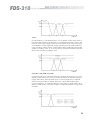
11.7 CD Horn
equalisation switch
Selecting the rear panel switch CD EQ will insert a correcting equalisation to
all relevant MID and HIGH outputs. This is confirmed on the front panel by the
appropriate LED. The amplifier response of the equalisation is shown if figure
11.2.
Fig 11.2 CD Horn EQ
response
Modern constant directivity horns are often used in sound system as they have
good control of dispersion, and are often used in 2-way systems at low
crossover frequencies. However, their output falls off progressively above
4kHz, and to compensate for this extra boosting EQ is used. The correcting EQ
in the FDS-318 is designed to accurately match horn manufacturers
specifications, and restores the high frequency output.
Care should be exercised in the use of this function, as it can be potentially
dangerous if used on systems not utilising Constant Directivity components.
The table in figure 11.1 shows which outputs have the option, dependent on
the mode selected.
11.8 MONO LO
switch
26
Because human hearing is insensitive to the location of low frequency sound
sources below 100Hz, stereo operation is normally dispensed with for subwoofer systems. Selecting the MONO LO switch on the rear panel of the FDS318 automatically sums the left and right hand inputs signals for the low
frequencies. The table in figure XX indicates which outputs are affected for
each mode , and a front panel LED lights to confirm the function is selected.
This function does not operate in the 2-way modes.
!!! CAUTION - Important Notes !!!
SERVICE SECTION
12.0
Service Section
12.1 Chassis/0V
Removal
The FDS-318 has the signal 0v ground connected to the metal chassis, which
in turn is connected to the safety ground. In the unlikely event that you need to
remove this link, or if you need to add a small impedance to reduce earth loop
currents, then proceed as follows.
Since both the audio inputs and outputs are wired fully balanced, we strongly
recommend that you fully recheck all wiring for correctness, prior to
proceeding.
Under no circumstances should the incoming ground wire be disconnected
from the power line cord, or from the internal chassis connection as an
alternative to this procedure.
• Disconnect the mains power cord and remove the units' top cover.
• Locate the long green wire positioned at the rear of the unit, which is
terminated at the rear panel metalwork at a point in between the input and
output connectors.
• Remove the end of this wire link from the chassis connection, fold over, and
insulate fully.
• The signal/0V ground is now isolated for the chassis.
The other green wire terminated onto this chassis bolt is connecting the
output XLR Pin 1 connections to chassis. Under no circumstances is it
recommended that this link is removed.
!!! WARNING - Refer all servicing to qualified service personnel !!!
Risk of electric shock if the unit is opened.
BSS Audio accepts no responsibility for injury
subsequent to opening of the unit.
27
!!! CAUTION - Important Notes !!!
SERVICE SECTION
12.2 Transient
Suppressor
Replacement
The primary of the mains transformer is protected against high voltage spike
interference by two voltage dependent resistors. These provide a short circuit
to voltage peaks in excess of their maximum rating.
Should the unit be inadvertently connected to 3 phase line/line voltages, or to
240V when selected to 120V, or any other incorrect voltage, these suppressors
are likely to fail in a protective short circuit mode. This will be demonstrated
by repeated mains fuse failure when powering up the unit.
Even in this case of extreme overvoltage the unit is protected against failure,
and the simple removal of these suppressors will allow the unit to be used
again. It is important that they are replaced as soon as possible to ensure
continued protection.
The two VDRs are mounted on a small circuit board attached to the rear panel
of the 120/240V selector switch. Ensure that the unit is disconnected from the
mains power before removing the suppressors.
Figure 12.1 indicates the location and specification for the suppressors.
Figure 12.1 Suppressor
location
12.3 Internal DC
fuse check
The internal DC fuses are located around the mains transformer, and are
labelled FS1, FS2 and FS3.
The unit should be disconnected from the mains supply before the lid is
removed.
!!! WARNING - Refer all servicing to qualified service personnel !!!
Risk of electric shock if the unit is opened.
BSS Audio accepts no responsibility for injury
subsequent to opening of the unit.
28
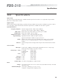
Specifications
13.0
Specifications
Input section
12k ohms electronically balanced, +20dBu maximum input level via XLR 3-31 or equivalent. Input CMMR
better than -50dB, 50Hz to 15kHz.
Output section
Electronically balanced and floating, capable of driving +26dBu into 600 ohms (+26dBm) or greater via XLR 332 or equivalent. When unbalanced, maximum output level is +20dBu into 600 ohms or greater.
System performance
Frequency Response:
THD+ noise:
Output noise:
Output level control:
Signal metering:
Modes:
Mono Lo:
Subsonic high pass filter -3dB at 15Hz, 6dB/Oct.
Ultrasonic low pass filter -3dB at 30kHz, 12dB/Oct.
Better than 0.05% 20Hz-20kHz, any level up to +18dBu.
Better than -85dBu, 22Hz to 20kHz.
+6dB gain to OFF. Calibrated 0dB gain marker.
Signal present LED -20dBu at output connectors.
Signal overload LED +10dBu at output connectors.
Stereo 4-way, stereo 3-way, four channels 2-way. Stereo 4-way includes
options for extra overlapping high pass and extra overlapping low pass
outputs.
Sums the output of left and right LOW outputs when selected (Stereo modes
only).
Crossover filters
Filter type:
Sweep range
4-way:
3-way:
2-way Hi:
2-way Mid:
2-way Lo:
CD Horn EQ:
Fourth order, 24dB/Oct Linkwitz-Riley adjustable over 10:1 sweep range.
Mode switching includes x10 and /10 scaling.
Lo-LoMid:
200Hz-2kHz
LoMid-HiMid:
200Hz-2kHz
HiMid-Hi:
1k25-12k5Hz
Lo-Mid:
200Hz-2kHz
Mid-Hi:
200Hz-2kHz
Lo-Hi:
2kHz-20kHz
Lo-Hi:
200Hz-2kHz
Lo-Hi:
20Hz-200Hz
First order, rising 6dB/Oct. +3dB at 3k5Hz.
Power
Voltage:
Dimension/Weight:
AC 40VA 50-60Hz, 96V-132V or 192V-264V selectable externally. Anchored
2M power cord.
44.5 x 483 x 288mm (1.75" x 19" x 11.3")
4.2kg Net. 5.2kg packed in shipping carton.
29
Warranty Information
14.0
Warranty Information
This unit is warranted by BSS Audio to the original end user purchaser against
defects in workmanship and the materials used in its manufacture for a period
of one year from the date of shipment to the end user.
Faults arising from misuse, unauthorised modifications or accidents are not
covered under this warranty. No other warranty is expressed or implied.
If the unit is faulty it should be sent, in its original packaging, to the supplier or
your local authorised BSS Audio dealer with shipping prepaid.
You should include a statement listing the faults found. The unit’s serial
number must be quoted in all correspondence relating to a claim.
IMPORTANT
We recommend that you record your purchase information here for future
reference.
Dealer Name:
Dealer Address:
Post/Zip Code:
Dealer Phone No.:
Dealer Contact Name:
Invoice/Receipt No.:
Date of Purchase:
Unit Serial Number:
In keeping with our policy of continued improvement, BSS Audio reserves the
right to alter specifications without prior notice.
The FDS-318 was designed and developed by BSS Audio, Hertfordshire,
England.
Phone (+44) (0)1707 660667. Fax (+44) (0)1707 660755.
World Wide Web address: http://www.bss.co.uk
30
Index
Index
B
Balanced wiring
L
15
C
CD EQ switch
CD Horn equalisation switch
Chassis/0V Removal
Connections
audio
input
output
Controls
crossover frequency
adjustment
Mute switch
output level
polarity reverse switch
signal level indicators
Crossover frequency adjustment
17, 25
Crossovers
Active v. Passive
advantages
20
26
27
15
19
19
17
17
17
17
18
5
6
7
D
Dimensions
12
E
Earthing
procedure
Main power switch
Mains fuse
Mains power
requirements
Modes
2-way HI, 2-way MID,
2-way LO
3-way
4-way
4-way HP
4-way LP
MONO LO switch
MONO LOW switch
Mute switch
19
18
13
22
23
23
22
22
22
26
20
17
O
Output level alignment
Output level control
Output MUTE switch
Output signal level indicators
Polarity reverse switch
Power switch
Powering up
10
R
14
18
Rear Panel
Rear panel switch LED
25
17
25
26
17
19
14
10
18
S
16
I
Input connections
Installation
Invisible slopes
M
13
G
Ground loop control
18
18
8
P
F
Front Panel
Fuse
AC Power
Mains power
LED
rear panel switch
select mode
Linkwitz-Riley
19
12
8
Select mode LED
SELECT MODE switch
Service section
Signal level indicators
Specifications
Switch
CD EQ
mains power
18
20
27
18
29
20, 26
19
31
Index
MONO LO
Output MUTE
Output polarity reverse
select mode
Voltage selector
20, 26
25
25
20
19
T
Transient Suppressor
Replacement
28
U
Unbalanced wiring
Unpacking
User Notes
15
9
33
V
Voltage selector switch
Voltage settings
19
13
W
Warranty Info.
Wiring convention
30
15
Z
Zero Phase difference
32
8
User Notes
33
User Notes
34
User Notes
35
User Notes
36