1
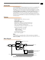
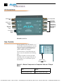
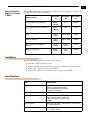
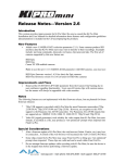
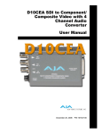
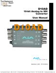
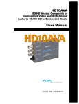
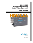
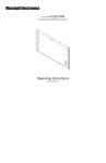
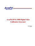
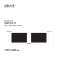
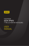
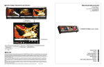
HD10MD3 HDTV
HD to SDI Down Converter
User Manual
September 21, 2006 P/N 101638-01
Test Equipment Depot - 800.517.8431 - 99 Washington Street Melrose, MA 02176 - FAX 781.665.0780 - TestEquipmentDepot.com
AJA HD10MD3 HD to SDI Down Converter User Manual — Introduction
Introduction
The AJA HD10MD3 is a miniature digital downconverter for converting HD-SDI
video to standard definition SDI and analog component composite video. The
HD10MD3 uses a full 10-bit data path and a multi-point interpolation to produce
excellent quality down-converted video. In addition, the HD10MD3 converts either
23.98/24Hz 1080p23.98sf or 1080p24sf to a 59.94 Hz output video using the
standard 3:2 pulidown technique. The output can be formatted for either 4:3 or 16:9
standard definition monitors. For 4:3 monitors, the output can be formatted for
either the Letterbox or Crop modes. Four channel AES embedded audio is passed to
the SDI output. The HD1OMD3 is also dual-rate in that SDI inputs pass to the SDI
and analog outputs.
1
Features
• Broadcast-Quality HD to SD down conversion
• Multi-Standard
• Dual-rate HD-SDI/SDI input
• HD-SDI/SDI outputs
• HD-SDI input: SMPTE 292/296 HD-SDI digital video
• HD-SDI outputs: Equalized and buffered copy of input
• SDI output: SMPTE 259 SDI digital video
• Analog outputs: Component or Composite video (10 bit)
• Input formats:1080i 50, 59.94, 60 Hz
1080psf: 23.98, 24, 25, 29.97, 30
1080p: 23.9B, 24, 25, 29.97, 30
1035i: 59.94, 60 Hz
720p: 50, 59.94, 60 Hz
• External Dipswitch Configuration
• Power: 5-18V unregulated
Note:
The HD10MD3 automatically switches to PAL anytime the input is 1080i 50,
1080psf 25 or 1080p25. All other frames rates have an NTSC output: 60, 59.94, 30,
29.97, 24 and 23.98.
Block Diagram
3:2 Pulldown Synchronization
RP188/RP215
Timecode
Extraction
Cable EQ
De-serializer
H&V
Filtering and
Decimation
HD or SD
Input
Embedded
Audio
Extraction
Audio
Embedding &
RP188
Timecode
Embedding
Serializer
SDI Output
Delay
D/A
Conversion
Y
G
Pb
B
Composite
Y
Pr
R
C
Component/Composite Outputs
(selected by DIP switch)
HD-SDI Out 1
DA Outputs
HD-SDI Out 2
HD10MD3 HD to SDI Down Converter, Block Diagram
3
4
I/O Connections
SDI Output BNC
HD/SD Input
BNC
Composite/
Component
Output BNCs
HDSD Loop
Output 1
BNC
Configuration
Determined by
DIP switch on
other side of
Converter
HD Loop
Output 2
BNC
+ 5 to 18VDC
Power
Input
HD10MD3, Side View
User Controls
The user interface for the HD10MD3 is an 8switch DIP accessible through a cut-out in the
bottom of the unit. Use the DIP switches to
configure outputs, pedestal, blanking, and
enable or disable noise reduction.
1
2
3
4
5
6
7
8
The exact function of each DIP switch and
what it controls is described on the following
pages.
A jumper accessible by removing the DIPswitch side of the case (requires removal of 4
screws) allows you to select further options
described later.
8
DIP Switches
LEFT
RIGHT
Switch 1—Selects Component or Composite Video on 3 Output
BNCs
:
LEFT
RIGHT
Selects Component output
Selects composite video output
Test Equipment Depot - 800.517.8431 - 99 Washington Street Melrose, MA 02176 - FAX 781.665.0780 - TestEquipmentDepot.com
AJA HD10MD3 HD to SDI Down Converter User Manual — User Controls
Switch 2—Selects Type of Component Video on 3 Output BNCs
:
LEFT
RIGHT
Selects YPbPr
Selects RGB
Switch 3—Turns Pedestal OFF/ON. In YPbPr Mode, use BETA Levels
:
LEFT
RIGHT
Pedestal Off
Pedestal On. This setting also1
changes analog output to BETA
levels when in YPbPr mode
Switch 4—Format Crop Letterbox OFF/ON
:
LEFT
RIGHT
No crop
Crop On—if S5 switch MONITOR is
set to 4:3 position
Switch 5—Selects Monitor Output to 4:3 or 16:9
:
LEFT
RIGHT
Selects 4:3
Selects 16:9
Switch 6—Turns Focus ON/OFF
LEFT
RIGHT
Turn Focus OFF
Turn Focus ON; zoom to center 720
x 486 image
Switch 7—Turn 4:3 Graticule ON/OFF
:
LEFT
RIGHT
Turn Graticule OFF
Turn Graticule ON (4:3 safe area)
Note: Switch 8 has no function.
5
6
Jumper Settings
Jumper J8 is located next to the DIP Switch. To access it, remove the back of the
HD10MD3 case by first removing the 4 phillips screws that secure it. The meaning of the
jumper settings is described in the illustration below:
1
2
3
6
5
4
Jumper
J8
Jumper Between Pins 1 and 2:
ON = RP215 is used to synchronize 3:2 pulldown sequence
OFF = RP188 is used.
In both cases the “A Frame” is synchronized to frame with timecode “xx:00”
Jumper Between Pins 5 and 6:
ON = Output start of vertical blanking lines up with input start of vertical blanking
OFF = Output start of vertical sync lines up with input start of vertical sync (per RP168)
AJA HD10MD3 HD to SDI Down Converter User Manual — Installation
Output Selection
Matrix For Output
3 BNCs
The following table shows the combinations of DIP switch settings required to configure the
three BNCs below the SDI Output BNC.
DIP Switch
#1
DIP Switch
#2
DIP Switch
#3
1 Composite and 1 Y/C (Pedestal)
RIGHT—
CMPSTE
N/A
RIGHT
1 Composite and 1 Y/C (no pedestal)
RIGHT—
CMPSTE
N/A
LEFT
RIGHT—RGB1
LEFT
Output Format
RGB
LEFT—
CMPNT
RGB with pedestal
LEFT—
CMPNT
RIGHT—RGB
RIGHT
SMPTE component (BETA625)/
EBU-N10
LEFT—
CMPNT
LEFT—
YPbPr/
LEFT
BETA 525 component
LEFT—
CMPNT
LEFT—
YPbPr/
RIGHT
Installation
Typically, HD10MD3 installation consists of the following:
1.
2.
3.
4.
disconnect +5VDC from the convertor
configure the DIP switch for the desired equipment configuration and video formats
connect video equipment to the convertor BNCs
apply +5VDC power to the converter (AJA power supply model DWP)
Specifications
Item
Specification
Formats
1080i 50/59.94/60Hz
1080p/psf 23.98/24/25/29.97/30 Hz
720p 23.98/24/25/29.97/30/50/60Hz
(Automatic Configuration)
Inputs
HD-SDI or SDI SMPTE 259/292/296, 10-bit, BNC
Outputs
SDI, SMPTE 259M, 10-bit, BNC
YPbPr - SMPTE, EBU-N10, Betacam
RGB, NTSC, PAL, YC (S-Video), 10-bit
3 x BNC
Down Conversion
Multi-point interpolation. 10-bit processing. 3:2 conversion
for 23.96/24p/psf inputs
Frequency Response
Y +0, -.5db to 30 MHz
C +/- .25db to 15 MHz
7
8
Item
Specification
User Controls
ExternalDipswitch:
Output Video Format
4:3/16:9 MonitorSelect
Letterbox/Crop
Pedestal (Output)
4:3 Safe-Zone Graticule Overlay
Size
5.8" x 3.1" x 1 (147 x 79 x 25mm)
Power
5-18V, 5 watts. Requires power supply.
Test Equipment Depot - 800.517.8431 - 99 Washington Street Melrose, MA 02176 - FAX 781.665.0780 - TestEquipmentDepot.com