1
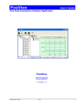
WiFi-500 Sensor Series Wireless Data Logging Sensors User's Guide Document Revision 5 May 2014 © Copyright 2014 Trademark and Copyright Information Measurement Computing Corporation and the Measurement Computing logo are either trademarks or registered trademarks of Measurement Computing Corporation. Refer to the Copyrights & Trademarks section on mccdaq.com/legal for more information about Measurement Computing trademarks. Other product and company names mentioned herein are trademarks or trade names of their respective companies. © 2014 Measurement Computing Corporation. All rights reserved. No part of this publication may be reproduced, stored in a retrieval system, or transmitted, in any form by any means, electronic, mechanical, by photocopying, recording, or otherwise without the prior written permission of Measurement Computing Corporation. Notice Measurement Computing Corporation does not authorize any Measurement Computing Corporation product for use in life support systems and/or devices without prior written consent from Measurement Computing Corporation. Life support devices/systems are devices or systems which, a) are intended for surgical implantation into the body, or b) support or sustain life and whose failure to perform can be reasonably expected to result in injury. Measurement Computing Corporation products are not designed with the components required, and are not subject to the testing required to ensure a level of reliability suitable for the treatment and diagnosis of people. SM WiFi-500-Sensor-Series.docx Table of Contents Preface About this User's Guide ....................................................................................................................... 5 What you will learn from this user's guide ......................................................................................................... 5 Conventions in this user's guide ......................................................................................................................... 5 Where to find more information ......................................................................................................................... 5 Chapter 1 Introducing the WiFi-500 Sensor Series Wireless Data Loggers ..................................................... 6 System requirements and recommendations ....................................................................................................... 6 Requirements for Cloud storage........................................................................................................................................ 6 WiFi Sensor Software/Cloud features ................................................................................................................ 6 Chapter 2 Setting Up a Device ............................................................................................................................... 8 Connecting the device to a network .................................................................................................................... 8 Logging sessions explained .............................................................................................................................................. 9 Chapter 3 Storing Device Data on the PC .......................................................................................................... 10 Changing device logging settings ..................................................................................................................... 10 Configuring alarms ..........................................................................................................................................................11 Positioning the device ....................................................................................................................................... 13 Viewing data on the PC .................................................................................................................................... 13 Graph viewing options...................................................................................................................................... 15 Creating and viewing data files ........................................................................................................................ 15 Saving all data to a .csv file .............................................................................................................................................15 Saving a portion of data to a .csv file ...............................................................................................................................15 Viewing a text file of logged data ....................................................................................................................................16 Exporting data to a file.....................................................................................................................................................16 Printing a graph ................................................................................................................................................ 16 Configuring a device wirelessly from the PC ................................................................................................... 16 Changing the device arrangement ....................................................................................................................................16 Deleting device readings ..................................................................................................................................................17 Resetting a device out of an alarm state ........................................................................................................... 17 Muting the audible alarm .................................................................................................................................. 17 Displaying device properties ............................................................................................................................ 17 Deleting a device .............................................................................................................................................. 18 Changing device logging settings ..................................................................................................................... 18 Chapter 4 Storing Device Data on the Cloud ..................................................................................................... 19 Completing the Cloud setup ............................................................................................................................. 19 Positioning the device ....................................................................................................................................... 19 An overview of the Cloud environment ........................................................................................................... 20 Viewing device information ............................................................................................................................. 21 Archiving, clearing, and deleting device readings ............................................................................................ 22 Archiving data .................................................................................................................................................................22 Clearing data ....................................................................................................................................................................22 Deleting a device and data ...............................................................................................................................................23 Displaying device properties ............................................................................................................................ 23 Changing device logging settings ..................................................................................................................... 24 Setting up email alerts ...................................................................................................................................... 26 3 WiFi-500 Sensor Series User's Guide Customizing email alerts..................................................................................................................................................26 Selecting a device location (Professional Cloud accounts only) ...................................................................... 27 Viewing graphed data ....................................................................................................................................... 28 Graph display options ......................................................................................................................................................28 Exporting a graph to PDF (Personal and Professional accounts only) ............................................................. 29 Printing a graph (Personal and Professional accounts only) ............................................................................. 29 Viewing sample values ..................................................................................................................................... 29 Exporting data to a comma-separated values (.csv) file (Personal and Professional accounts only) ................ 30 Viewing logging session audit information ...................................................................................................... 30 Exporting session audit information to a .pdf file (Professional accounts only) .............................................. 30 Viewing a logging session summary ................................................................................................................ 31 Viewing, emailing, and deleting event logs ...................................................................................................... 31 Device Operation ................................................................................................................................. 33 Device components........................................................................................................................................... 33 Restarting a device............................................................................................................................................ 35 Resetting a device ............................................................................................................................................. 35 Resetting maximum and minimum values ........................................................................................................ 35 Turning a device off ......................................................................................................................................... 35 Battery and power features ............................................................................................................................... 35 Recharging the battery .....................................................................................................................................................35 Optimizing battery performance ......................................................................................................................................36 Data security if device battery runs out............................................................................................................................36 Data security during a power outage ................................................................................................................................36 MAX, MIN and battery symbol are all displayed on the LCD at the same time ..............................................................36 Permanently powering a device .......................................................................................................................................36 Monitoring AC power to a device ....................................................................................................................................36 Updating firmware ............................................................................................................................................ 37 Chapter 5 Tips and Troubleshooting .................................................................................................................. 38 Device/WiFi/Cloud communications ............................................................................................................... 38 Software does not detect device connected to PC ............................................................................................................38 Cannot connect device to WiFi network ..........................................................................................................................38 Cannot connect device to Cloud ......................................................................................................................................38 Cannot save device settings using Set-Up Device option ................................................................................................38 WiFi network stops working (power loss, and so on) ......................................................................................................39 WiFi icon on LCD is flashing ..........................................................................................................................................39 Checking WiFi router for 802.11b compatibility .............................................................................................................39 Communication over a Virtual Private Network (VPN) ..................................................................................................39 Cloud features ................................................................................................................................................... 39 Data security on the Cloud ...............................................................................................................................................39 Time-zones on the Cloud .................................................................................................................................................39 4 Preface About this User's Guide What you will learn from this user's guide This user's guide describes the device setup and configuration, data file conversion and export, and device control features included with Measurement Computing WiFi-500 Sensor Series wireless data loggers. Conventions in this user's guide For more information Text presented in a box signifies additional information and helpful hints related to the subject matter you are reading. Caution! Shaded caution statements present information to help you avoid injuring yourself and others, damaging your hardware, or losing your data. bold text Bold text is used for the names of objects on a screen, such as buttons, text boxes, and check boxes. italic text Italic text is used for the names of manuals and help topic titles, and to emphasize a word or phrase. Where to find more information Additional information about WiFi-500 Sensor Series wireless data loggers is available on our website at www.mccdaq.com. You can also contact Measurement Computing Corporation by phone, fax, or email with specific questions. Knowledgebase: kb.mccdaq.com Phone: 508-946-5100 and follow the instructions for reaching Tech Support Fax: 508-946-9500 to the attention of Tech Support Email: [email protected] 5 Chapter 1 Introducing the WiFi-500 Sensor Series Wireless Data Loggers Thank you for purchasing a WiFi-500 Sensor Series wireless data logger from Measurement Computing. This user's guide explains how to perform the following tasks: set up a WiFi-500 Sensor Series wireless data logger to connect to a wireless network configure a device to log environmental data and transmit it wirelessly to a host PC or web-based Cloud account export logged data to a comma-delimited text file and to a Microsoft® Excel® spreadsheet view readings and indicators on a WiFi-500 Sensor Series data logger System requirements and recommendations WiFi-enabled PC or laptop running Windows® 8/7/ Vista®/XP, 32- and 64-bit 802.11b-compliant router or access point running one of the following supported security protocols: o WEP 64 bit (Passkey encryption only) o WEP 128 bit (Passkey encryption only) o WPA-PSK o WPA2-PSK Micro-USB cable (shipped with sensor) Microsoft mouse or compatible pointing device Microsoft Excel® 2000 or greater (optional) Requirements for Cloud storage A FilesThruTheAir™ Cloud account is required for Cloud-based data storage. A link is available in the WiFi Sensor Software to create an account. Your WiFi-500 Sensor Series device may also require a firmware update in order to access the Cloud. Refer to Updating firmware on page 37 for instructions. WiFi Sensor Software/Cloud features The WiFi Sensor Software can set up a device data storage and device configuration using locally on a PC, or remotely using a Cloud account and any device that supports a web browser – smart phone, tablet, laptop, or desktop computers. WiFi-500 Sensor Series device is accessible from any location – local or remote – within range of the connected WiFi network or from the Cloud Password-protected access using SSL sessions for security Local and remote device configuration of the following settings: o Device name o Temperature scale o Sample rate o Transmission period o Alarms, including alarm hold and alarm delay settings o Record on-site checks of devices Data export and graph printing 6 WiFi-500 Sensor Series User's Guide WiFi Sensor Software/Cloud features The Cloud interface also offers instant email alerts to as many as 100 addresses for alarms, AC power outage, low battery charge, loss of network connection, and other device-specific problems. Cloud accounts are web-based and can be accessed at https://www.wifisensorcloud.com/ using a browser on a phone, tablet, PC, or Mac®. The following optional Cloud services are also available (depends on level of Cloud account being used -- Free, Personal, or Professional). Audit trail export to provide a documentary record of changes Multiple user access Individual time zones per user Graphical and tabular data displays with date/time references Unlimited data storage (Personal and Professional accounts only) Printing a graph (Personal and Professional accounts only) Unlimited devices (Professional accounts only) Refer to www.wifisensorcloud.com/accountdifferences.aspx for a comparison of Free, Personal, and Professional Cloud account features 7 Chapter 2 Setting Up a Device To set up a WiFi-500 Sensor Series wireless device for use on either the PC or the Cloud, make sure you have the following items: Micro-USB cable 802.11b-compliant router or access point WiFi-enabled computer with WiFi Sensor Software installed The computer running the WiFi Sensor Software must be connected to the router either wirelessly or by Ethernet cable. Connecting the device to a network Complete the following steps to connect a WiFi-500 Sensor Series data logger to a WiFi network: 1. Find the password for the router (often located on the bottom of the router). 2. Double-click the WiFi Sensor Software desktop icon ( 3. Click either Set-Up Device»On This PC or Set-Up Device»On The Cloud in the main software screen. ) to run the software. Figure 1: WiFi Sensor Software Set-Up Device options 4. Remove the rubber plug that protects the USB connector on the sensor and connect the sensor to the computer using the Micro-USB cable. Figure 2: Removing rubber plug over USB connector Allow any security access highlighted by your firewall or antivirus program if you are prompted. A CONNECTED message indicates the WiFi Sensor Software has detected the device. If a NOT CONNECTED message displays, reconnect the USB cable and the software automatically attempts to detect the device. 5. Once a list of available WiFi networks displays, click on a network to connect to the device. This must be the same network that is connected to the host computer. If a FAILED message displays, click Refresh Connections until a list of networks displays. 6. Enter the network password and click CONNECT. Problems connecting? If a NOT CONNECTED dialog box displays, refer to Cannot connect device to WiFi network on page 38 8 WiFi-500 Sensor Series User's Guide Connecting the device to a network Advanced Network Options To enter additional network settings, select the Enter Advanced Network Options Next checkbox and enter the IP address, subnet mask and default gateway. You can also lock the device so that it only connects to one wireless access point. This may be necessary if you have multiple access points with the same SSID. Enter the MAC address of the access point. Logging sessions explained To manage data received from your device efficiently, both the WiFi Sensor Software and the Cloud divides data up into sessions. A device begins a session when it starts logging. If you make any changes to the device such as a sample rate or alarm level change, the software or Cloud closes and saves the current session, and a new session is created. All sessions are marked with a date and time to show the period that they cover, together with an audit trail showing the changes which caused a new session to start. Once you successfully connect the device to the WiFi network, proceed to one of the following sections: If you selected Set-Up Device»On This PC, proceed to Storing Device Data on the PC on page 10. If you selected Set-Up Device»On The Cloud, proceed to Storing Device Data on the Cloud on page 19. 9 Chapter 3 Storing Device Data on the PC When you select View Devices»On This PC and connect a device to a WiFi network, the GENERAL SETTINGS dialog box displays with general device and logging settings for the a WiFi-500 Sensor Series data logger Changing device logging settings Complete the following steps to change device logging settings from the PC: 1. Enter the following information In the GENERAL SETTINGS dialog box: o Name Device to give it a unique identity: Enter a unique name to identify the device on the WiFi o Select temperature scale: Click °C or °F. network. Select sample rate: Select a sample rate between 10 Seconds and 12 Hours from the drop-down list. This value sets how often the device takes a reading. o Select how often the device will communicate with the PC: Select how frequently – between every 1 Minute to every 24 hours – the device transmits samples to the host computer For example, if the sample rate is set to 10 Seconds and the sample transmission frequency is set to 1 Minute, the device transmits six samples to the computer every minute (60 seconds ÷ 10 seconds = 6 samples). o Figure 3: GENERAL SETTINGS dialog box The more frequently data is transmitted the quicker battery power is depleted. By increasing the time between transmissions, the battery charge lasts longer. 2. Click Next. 10 WiFi-500 Sensor Series User's Guide Changing device logging settings Configuring alarms In the TEMPERATURE ALARMS and HUMIDITY ALARMS dialog boxes, you configure the following alarm settings: Low/High Alarms – Enable alarms that are triggered when a device logs data that exceeds a high temperature/humidity value, or that is below a low temperature/humidity value. The low alarm value must be less than the high alarm value. Alarm Delay – Filter out unwanted alarms by selecting a delay time from the dropdown box. For example, when monitoring the temperature of a refrigerator, you might not need to know if the temperature exceeds the alarm level briefly – when someone opens and closes the door, for instance – but you do need to know if someone leaves the door open for more than one minute. You can set a separate delay for temperature and humidity alarms. Alarm Hold – Holds an alarm state even when the temperature/humidity returns to an acceptable range. For example, if the high temperature alarm is set to 42°C and the measured temperature rises to 46°C, an alarm is triggered. If the reading then drops down to 41°C when the Alarm hold checkbox is selected, the device retains its alarm status. If Alarm hold is not selected, the device reverts back to normal status, and the only way to check missed alarms is to review the logged data. Audit Check – Record an event on the graph by pressing and holding the device button for three seconds to indicate an onsite check of the device. Complete the following steps to configure WiFi-500 Sensor Series temperature and humidity alarm settings: 1. Select the On option button for Low alarm to enable a low alarm, and then select a low temperature/humidity alarm value from the list. 2. Select the On option button for High alarm to enable a high alarm, and then select a high temperature/humidity alarm value from the list. 3. Select the On option button for Alarm hold to retain the alarm status when the temperature/humidity returns within the alarm range. 4. Select a delay time from the Delay alarm trigger by listbox to filter out unwanted alarms. 5. Select the Enable option button for Audit Check to record an event on the graph when a device is checked onsite (TEMPERATURE SETTINGS dialog box only). 6. If you are setting up a device that includes a thermistor probe, select the probe type you are using from the drop-down listbox. Figure 4: Probe type list Refer to the label attached to the probe cable for the probe number. Selecting an incorrect probe type causes inaccurate measurements. Figure 5: Probe type label 11 WiFi-500 Sensor Series User's Guide Changing device logging settings Figure 6: TEMPERATURE ALARMS dialog box Figure 7: HUMIDITY ALARMS dialog box 7. Click Next on both the TEMPERATURE ALARMS and HUMIDITY ALARMS dialog boxes when you finish configuring alarm settings. 8. Click Next. 9. Click Finish in the dialog box, disconnect the USB cable from the device and place the device in the location you want to monitor. Note: If you receive a Set-Up Failed message, refer to Cannot save device settings using Set-Up Device option on page 38 12 WiFi-500 Sensor Series User's Guide Positioning the device Positioning the device The device signal strength displays on the device LCD. The number 10 indicates a strong signal; the number 1 indicates a weak signal. Avoid heat, radio emissions, and physical obstructions Avoid placing a device near sources of heat and radio emission. Also, physical obstructions between the router and device can affect the range of the device. You can use WiFi extenders to improve the range of the device. The WiFi signal indicator ( ) has three states: o not displayed – the device has not yet been set-up and configured to a WiFi network o flashing – not communicating with WiFi Sensor Software o solid – successful communication with WiFi Sensor Software Viewing data on the PC To view data for a specific logging session on the PC, complete the following steps: 1. Click View Devices»On This PC in the main software screen. All WiFi-500 Sensor Series devices connected to the WiFi network through the host computer display. 2. Select the device you want to view, and click View Data at the bottom of the Existing devices screen. Figure 8: Existing devices screen By default, all logging sessions for the current month are listed. You can change the date range by using the date buttons.: o o Use the and Use the and want to view. date buttons to scroll through years. date sliders to specify a time period within the year containing the session(s) you 13 WiFi-500 Sensor Series User's Guide 3. Viewing data on the PC Click on the logging session you want to view. Figure 9: Selecting a logging session A graph displays with checkboxes to show the following information: o temperature readings o relative humidity readings (if supported) o temperature alarm readings o relative humidity alarm readings (if supported) o dew point (if supported) Figure 10: Graph of WiFi-500 sensor data (temperature/humidity example) 14 WiFi-500 Sensor Series User's Guide Graph viewing options Graph viewing options The View menu and toolbar The graph includes the following viewing options: View menu option/toolbar icon Function View»Toolbar View»Status Bar Display or hide the toolbar at the top of the graph. Display or hide the status bar at the bottom of the graph Zoom in to view a narrower range of graph data. View»Zoom In or click toolbar View»Zoom Out or click toolbar View»Data Range on the on the View»Gridlines View»Mark Samples Zoom out to view a wider range of graph data. Enter a time/date range of data to view on the graph. Display or hide X-axis and Y-axis gridlines on the graph. Adds a small circle to the plot line to indicate each sample. Creating and viewing data files You can export logged data and graph images to different file formats, and open them for viewing and analysis. Saving all data to a .csv file Complete the following steps to save all logged data to a text file: 1. Click Save on the toolbar. 2. Enter a filename and browse for the location to save the file, and click Save. Saving a portion of data to a .csv file Complete the following steps to save a portion of logged data to a text file: 1. Zoom in on the section of the graph containing the data to save (refer to Graph viewing options above). 2. Click Save on the toolbar. 3. Enter a filename and browse for the location to save the file, and click Save. 15 WiFi-500 Sensor Series User's Guide Printing a graph Viewing a text file of logged data To open a text file of logged data, click View Saved Data in the main software screen and browse for the file using the Locate File dialog box. Figure 11: View Data option on main screen Exporting data to a file You can export data or graph images to one of following file formats: a comma-separated values (.csv) data file for later retrieval and analysis a .jpg image file of graph a .pdf of the data or of the graph an Excel® file (.xls) containing both the data and graph To export data, click Export and select file format from the menu. Printing a graph To print an image of the graph, click . Configuring a device wirelessly from the PC When you select View Devices»On This PC in the main software screen, the Existing devices screen displays all WiFi-500 Sensor Series devices that are actively connected to or that are temporarily disconnected from the network through the host computer. The operations you can perform on each displayed device are explained in the following sections. Changing the device arrangement To change how devices are arranged on the Existing devices screen, click the icons in the top right corner of the screen. View device images only View device images and information View device information only Right-click on a device to move it up, down, to the top of the list, or to the bottom of the list. You can also arrange all devices by name or by MAC address (the unique number assigned to each device on the network). 16 WiFi-500 Sensor Series User's Guide Resetting a device out of an alarm state Deleting device readings To delete the readings currently stored on a device and on the host computer, right-click on a device and select Delete Readings. All readings for the selected device are deleted from device memory and from the host computer. The device starts logging data again based on its settings. Data that has been saved or exported to a file is not deleted from the file(s). Resetting a device out of an alarm state To reset a device that is currently in an alarm state, right-click the device image and select Reset Alarm. The device returns to a normal, non-alarm state until the next alarm reading occurs. Muting the audible alarm The WiFi Sensor Software includes an audible alarm that sounds when a device is in an alarm state. Click to turn alarm muting on and off. Displaying device properties To view the current logging and alarm settings for a selected device, along with the device type, firmware version, MAC address, and the name of the connected WiFi network, click Properties in the Existing devices screen (refer to Figure 8 on page 13). You can also right-click the device image and select Device Properties from the context menu. Figure 12: Device Properties popup window 17 WiFi-500 Sensor Series User's Guide Deleting a device Deleting a device Complete the following steps to delete a device and all of its data sessions from the software: 1. Select a device in the Existing devices screen (refer to Figure 8 on page 13). 2. Right-click the device image and select Delete Device(s). 3. Click Yes in the Are you sure? dialog box. 4. Click Yes in the Archive Data dialog box to save device data to the host computer. You are prompted to select a location to save the archived data. Caution! If you are deleting the device in order to update the device firmware, MCC strongly recommends that you archive your data. All data is deleted from a device during a firmware update (refer to Updating firmware on page 37) Click No to skip saving device data and finish deleting the device. Once you delete a device, perform the Connecting the device to a network procedure on page 8 to reconnect the device to the network and access it through the software. Changing device logging settings To change the logging settings of a device over the network, select the device and click Change Device Settings in the Existing devices screen (refer to Figure 8 on page 13). Follow the steps at the beginning of the section Changing device logging settings from the PC on page 10 to change the device logging settings over the WiFi network. 18 Chapter 4 Storing Device Data on the Cloud Completing the Cloud setup The first time you set up a WiFi-500 Sensor Series device on the Cloud, the only setting you can change is the device name. All others settings are kept at their current values. Enter a device name and then click Next. 1. Disconnect the USB cable from the sensor and click Next in the Set-Up Complete dialog box. 2. Place the sensor in the location you want to monitor. Figure 13: Device settings when Cloud setup complete Positioning the device Avoid placing a device near sources of heat and radio emission. Also, physical obstructions between the router and device can affect the range of the device. You can use WiFi extenders to improve the range of the device. The device signal strength displays on the device LCD. The number 10 indicates a strong signal; the number 1 indicates a weak signal. The WiFi signal indicator ( ) has three states: o not displayed – the device has not yet been set-up and configured to a WiFi network o flashing – not communicating with WiFi Sensor Software o solid – successful communication with WiFi Sensor Software 19 WiFi-500 Sensor Series User's Guide An overview of the Cloud environment An overview of the Cloud environment When you log in to your Cloud account and successfully set up a device through the cloud, you are brought to the Cloud page on the web which has the following main options: Depending on your current account type, opens a page with options to upgrade or downgrade to different Free, Personal, and Professional Cloud accounts. Refer to www.wifisensorcloud.com/accountdifferences.aspx for a summary of account features. Opens a page with links to: Devices (Professional accounts only) the Devices page the Cloud Support page the My Settings page (where you can change date/time format for log files, your account email address and password, and control the frequency of Cloud emails) the Account page (where you can view account properties and email activity, and change personal information stored in the Cloud account) Opens the My Devices/Devices page which lists all devices set up for the Cloud account. The features on this page are explained in the following sections: Displaying device properties on the Cloud Archiving, clearing, and deleting device readings on the Cloud Changing device logging settings from the Cloud Setting up email alerts from the Cloud My Devices (Free and Personal accounts) Opens the Account page, where you can view account properties and email activity, and change personal information stored in the Cloud account. Opens the Cloud Support page, which has links to FAQs, and firmware downloads, video tutorials, a technical support request form. Only the features on the Home and My Devices/Devices pages are covered in detail in this guide. Refer to the support resources on the Cloud page for help with the features on other pages. 20 WiFi-500 Sensor Series User's Guide Viewing device information Viewing device information After logging in to your Cloud account, when you select View Devices»On The Cloud in the main software screen, the My Devices page opens in a browser and displays all WiFi-500 Sensor Series devices on the Cloud. To manage the data received from your device efficiently, the Cloud divides data into sessions. A device begins a session when it begins logging. If changes are made to the device configuration – such as sample rate or alarm level change, the Cloud closes and archives the current session, and creates a new session for the device. The number of devices you can connect to the Cloud depends on the type of Cloud account you have (Free, Personal, or Professional). Click on the Upgrade link for more information on account types and features. Figure 14: Devices page The Devices page displays the following information about each WiFi device setup for the Cloud. Device - Displays one of the following icons to indicate the device model: - Temperature-only device (such as a WiFi-501) - Temperature device with thermistor probe (such as a WiFi-501-TP) - Temperature/humidity device (such as a WiFi-502) Name - Displays the name of the device. Signal - Displays a bar graph indicating the signal strength. Battery - Displays a bar graph indicating the battery strength. Reading 1 - Displays the latest temperature reading. Reading 2 - Displays the latest humidity reading (if device measures humidity). Status - Indicates the connection status for active devices. May also indicate Setup pending if device settings were changed. When the device receives its new settings the next time it transmits to the Cloud, the Setup Pending status is removed. Data saved from past sessions have a status of Archived along with the archive date. 21 WiFi-500 Sensor Series User's Guide Archiving, clearing, and deleting device readings Archiving, clearing, and deleting device readings The Archive/Delete icon provides options to archive device data, clear device data, and delete a device and data from the cloud. Figure 15: Archive/Delete options An archived device session remains in the device list so all collected data can be accessed, but it is no longer active and logs no new data. A cleared device remains in the active device list; however, any previously acquired data is deleted. A deleted device is removed from the device list and all collected data can be deleted and cannot be recovered. Archiving data To archive the readings on an active device on the Cloud, complete the following steps: 1. Log in to your Cloud account and select View Devices»On The Cloud in the main software screen 2. Select the active device in the Devices page and click Archive/Delete. 3. Click Archive. The data from device is archived on the cloud. The archived data can be retrieved for display and analysis, but this device session no longer acquires new data. The device must be setup for the Cloud again in order to acquire new data. Refer to Setting Up a Device on page 8. Clearing data To clear the readings on an active device on the Cloud, complete the following steps: 1. Log in to your Cloud account and select View Devices»On The Cloud in the main software screen 2. Select the active device in the Devices page and click Archive/Delete. 3. Click Clear. The data is deleted from the device, and the device continues acquiring data based on its current settings. 22 WiFi-500 Sensor Series User's Guide Displaying device properties Deleting a device and data Complete the following steps to delete an active device and its data from the Cloud, complete the following steps: 1. Log in to your Cloud account and select View Devices»On The Cloud in the main software screen. 2. Select the active device in the Devices page and click Archive/Delete. 3. Click Delete. The device is deleted from the Devices page. The device must be setup for the Cloud again in order to acquire new data. Refer to Setting Up a Device on page 8. Displaying device properties To view the current logging and alarm settings for a selected device over the Cloud, along with the device type, firmware version, MAC address, and the name of the connected WiFi network, complete the following steps: 1. Log in to your Cloud account and select View Devices»On The Cloud in the main software screen. 2. Select the active device in the Devices page and click Properties. Figure 16: Properties popup on the Cloud 23 WiFi-500 Sensor Series User's Guide Changing device logging settings Changing device logging settings Complete the following steps to change device logging settings from the Cloud: 1. Log in to your Cloud account and select View Devices»On The Cloud in the main software screen. 2. Select the active device in the Devices page and click Change Settings. 3. To change the device name, click Device Name, enter a name, and then click Save. Figure 17: Device Name setting 4. To change the temperature scale and thermistor probe type (if supported by the device), click Temperature Scale (or Temperature Scale & Probes) o o o Select °C - Celsius or °F - Fahrenheit If the device includes a thermistor probe, select the probe type you are using. Refer to the label attached to the probe cable for the probe number. Selecting an incorrect probe type causes inaccurate measurements. Click Save. Figure 18: Temperature Scale and Probe Type settings 24 WiFi-500 Sensor Series User's Guide 5. Changing device logging settings To change the sample rate, click Sample Rate, select a sample rate from the list, and click Save. Figure 19: Sample Rate settings 6. To change the transmission period, click Transmission Period, select a transmission period from the list, and click Save. Figure 20: Transmission Period settings 7. To change the temperature/humidity alarms, click Alarm Settings & Audit Check, change any of the following settings, and click Save. o o o o Enable (On option) or disable (Off option) the low and high alarms for temperature and humidity (if supported). Enter alarm values for each enabled alarm. The low alarm value must be less than the high alarm value. To retain the alarm status when the temperature and/or humidity goes between the alarm range, click the On option button for Alarm Hold. For example, if the high alarm is set to 25 °C and the temperature rises to 26 °C, an alarm is triggered. If the temperature then drops down to 21 °C and Alarm hold is selected, the device retains its high alarm status. If Alarm hold is not selected, the device reverts back to normal status, and the only way to check missed alarms is to review the logged data. To filter out unwanted alarms by delaying the alarm trigger, select a delay time from the Alarm Delay Alarm Trigger by listbox. To record an event on the graph when a device is physically checked, select the Enable Audit Check checkbox. You indicate the device being checked by pressing and holding the device button for three seconds. 25 WiFi-500 Sensor Series User's Guide Setting up email alerts Figure 21: Alarm and Audit Check settings Setting up email alerts You can set up email alerts to notify you and others when alarms are triggered, and also send notification for any of the following events: AC Power - Reports a change in the state of AC power connected to your device. To monitor power, connect your device permanently using a USB charger and enable the AC Power email alerts. The Cloud sends an email if power fails and when power is restored. Battery Low - Report when the battery in your device is low and needs re-charging. For uninterrupted data recording, you can recharge at the site of the device using a USB 5V wall adapter or a portable USB battery pack. Loss of Connection - Reports when regular transmissions from your device are not received. The Cloud sends an email instructing you to check your WiFi network, device position, and battery charge. Device Problems - Reports when there is a problem with your device, such as a disconnected probe or readings out of range. Complete the following steps to set up email alert recipients over the Cloud: 1. Click Email Alerts. 2. Enter a Name and Email Address and click 3. Select the checkbox for each type alert to send to the recipient. 4. Repeat steps 1 through 3 for each email recipient you want to add. 5. Click Apply to save all recipients and settings. . Customizing email alerts When you set up email alerts, only select those events that you want to generate emails. If you are only interested in the measured alarm levels, deselect some other options you don’t need. When you set-up an alarm level, you can delay the onset of the alarm by a selectable period of time. For example, when monitoring the temperature of a chiller, you might not need to know if the temperature exceeds the alarm level briefly (when someone opens and closes the door, for instance), but you do need to know if someone leaves the door open. When using dual channel device devices, alarm delay is independently settable for each channel. 26 WiFi-500 Sensor Series User's Guide Selecting a device location (Professional Cloud accounts only) Have you set an alarm level that is too low or high? Every time a device goes into or out of alarm, an email is sent. If your device is constantly chattering around the alarm level, you receive more emails. To reduce email traffic further, you can choose to reduce the number of alerts, by periodically summarizing them into a single email. You can enable this option, and specify how often the summary emails are sent. Figure 22: Email Alert settings Selecting a device location (Professional Cloud accounts only) When you first set up a WiFi-500 Sensor Series device on a Professional Cloud account, the device is added to the NEW DEVICES location. Complete the following steps to move a device to another location on the Cloud: 1. Click Device Location. 2. Select the location where you to move the device and click Save. Figure 23: Device Location options 27 WiFi-500 Sensor Series User's Guide Viewing graphed data Viewing graphed data Complete the following steps to view graphed data for a specific logging session on the Cloud: 1. Log in to your Cloud account and select View Devices»On The Cloud in the main software screen. 2. Select the active device in the Devices page and click View Data. 3. Click on the Graph tab Figure 24: Data plotted on Sensor Session Data - Graph tab The Graph tab on the Sensor Session Data page displays the following information: o temperature readings o relative humidity readings (if supported) o high/low alarm levels (if configured) Graph display options Click Display Options to view or hide temperature readings, humidity readings, alarm levels, audit checks, and to mark samples. Figure 25: Display Options for Cloud graph Depending on the time range of the data acquired in the session, you can use the Zoom to view graphed data for a selected time period (6 hours, 12 hours, 1 day, 1 week, 1 month, 1 year, or all samples). Figure 26: Zoom Options for Cloud graph 28 WiFi-500 Sensor Series User's Guide Exporting a graph to PDF (Personal and Professional accounts only) Click-and-drag the date/time range controls connected to scroll bar to narrow the range of data to a select date and time. Figure 27: Date/time range controls Exporting a graph to PDF (Personal and Professional accounts only) Personal and Professional Cloud account users can export an image of the graph to a .pdf by clicking . with the Graph tab displayed. Printing a graph (Personal and Professional accounts only) Personal and Professional Cloud account users can print an image of the graph by clicking . Viewing sample values To view the value of each sample from a logging session on the Sensor Session Data page, complete the following steps: 1. Log in to your Cloud account and select View Devices»On The Cloud in the main software screen 2. Select the active device in the Devices page and click View Data. 3. Click on the Data tab. Figure 28: Data listed on Sensor Session Data - Data tab Each sample is listed on the Data tab. Use the green navigation links below the listing to browse through data in the session. 29 WiFi-500 Sensor Series User's GuideExporting data to a comma-separated values (.csv) file (Personal and Professional accounts only) Exporting data to a comma-separated values (.csv) file (Personal and Professional accounts only) Personal and Professional Cloud account users can export a logged data to a .csv file by clicking with the Data tab displayed Viewing logging session audit information To view and export audit information on the Sensor Session Data page for any logging session for the selected device, complete the following steps: 1. Click the Other Sessions tab. 2. Click on the session you want to display. Figure 29: Selecting session on Other Sessions tab 3. Use the scrollbar in the Session Audit frame to view additional session audit information. Exporting session audit information to a .pdf file (Professional accounts only) Professional Cloud account users can export session audit information to a .pdf file by clicking with the session information displayed. Figure 30: Session audit export to .pdf 30 WiFi-500 Sensor Series User's Guide Viewing a logging session summary Viewing a logging session summary To view a summary of a logging session on the Sensor Session Data page, complete the following steps: 1. Log in to your Cloud account and select View Devices»On The Cloud in the main software screen. 2. Select the device session in the Devices page and click View Data. 3. Click the Summary tab. Figure 31: Session summary information on Sensor Session Data - Summary tab The Summary tab displays device information, devices settings, and data statistics (minimum/maximum, average, and standard deviation. Viewing, emailing, and deleting event logs To view a log of device alarm, communication, power and other events, complete the following steps: 1. Log in to your Cloud account and select View Devices»On The Cloud in the main software screen. 2. Select the device session in the Devices page and click Event Logs. Figure 32: Event Logs page 3. The following event log options are available: o Click Clear Log to clear all events from the log. 31 WiFi-500 Sensor Series User's Guide o Viewing, emailing, and deleting event logs Click Send This Log to send an email to a recipient with the event log attached as a coma-separated values (.csv) file. You can enter an email address or, if you have a Professional account, the name of a registered Cloud account user. Figure 33: Send This Log options o Click Filter Event to select/deselect events that display in the event log. Figure 34: Filter Events options 32 Device Operation Device components The different readings and indicators on a typical WiFi-500 Sensor Series data logger are identified in Figure 35. Figure 35: WiFi-500 device components 1 2 3 4 Signal strength indicator Alarm indicator Min/Max value indicators Battery charge indicator 33 5 6 7 8 Temperature unit Device button Humidity reading Temperature reading WiFi-500 Sensor Series User's Guide Device components Press the screen cycle button to cycle through the different device displays: Figure 36: WiFi-500 device display cycle (WiFi-502 example) 34 WiFi-500 Sensor Series User's Guide Restarting a device Restarting a device To restart a device, hold the button for 10 seconds and then release it when flashes in the top right hand corner of the display. The device retains all settings but loses any data that has not been transferred to the computer. Resetting a device To reset a device to its factory settings, hold the button for 20 seconds until displays. Resetting to the factory state deletes all settings and previously recorded data. Resetting maximum and minimum values To reset the maximum and minimum values on a device, cycle through to the maximum or minimum reading display and hold the button for three seconds. The new minimum or maximum value is the temperature and humidity value read at the time of reset. Turning a device off The device remains on permanently unless the battery runs out. Battery and power features Recharging the battery Each WiFi-500 Sensor Series device is shipped partially charged with enough power for the initial set up and use. For optimum performance, use the USB cable provided to connect the device to a PC, a USB + 5V wall adapter, or a portable USB battery pack, and charge the device for 24 hours. From a very low battery state, it can take up to eight hours to fully charge a device. The battery status can be seen from the Devices page on the Cloud. Many factors affect the battery charge of the device, including: transmission period WiFi encryption method WiFi encryption key rotation frequency (determined by the Access Point or router) signal strength between access point or router and device the presence, volume, and type of WiFi traffic from other devices sample rate operating temperature. In tests, a battery life of over six months was regularly achieved with a transmission period of one hour or more. The battery charge indicator displays the battery charge status. Battery Charge Indicator (not displayed) (flashing) (solid) Battery Charge Status Battery charge sufficient Battery charge low – recharge by connecting the device to a computer using the MicroUSB cable provided Battery recharging If you have a critical process or do not wish to recharge devices, you can keep the USB charger plugged in continuously. 35 WiFi-500 Sensor Series User's Guide Battery and power features Optimizing battery performance To optimize your system to avoid excessive recharging cycles, data loggers include these features: Turn off the WiFi Sensor Software when it is not needed. Devices go into sleep mode when the WiFi Sensor Software is not running. No data is lost because it is stored on the device onboard memory, and alarm conditions are still recorded. When you restart the software, the device attempts to reconnect within 15 minutes. Once a device reconnects, all stored data is transmitted to the computer. The more frequent data is transmitted, the quicker battery power is depleted. By increasing the time between transmissions, the batteries last longer. The following factors significantly affect the battery life of the device: the transmission period the WiFi encryption method WiFi encryption key rotation frequency (determined by the Access Point or router) signal strength between access point or router and device volume, and type of WiFi traffic from other devices, sample rate, and operating temperature. In our tests, we regularly achieve battery life in excess of six months with a transmission period of one hour or more. Data security if device battery runs out The device takes no further readings when there is no power, but all readings taken prior to power loss are synchronized. Once the device is recharged, it reconnects to the Cloud and starts a new logging session. When using battery power, set suitable sample and transmission periods as these affect your battery life. If fast transmission periods and/or long term, uninterrupted logging is needed, power the device with AC power using a suitable USB power supply. Data security during a power outage The device continue recording at the sample rate you have set using battery power, and no data is lost. If a power outage occurs, the device continues to try to connect to your network until power returns and the access point or router becomes available again. The device then synchronizes all remaining data with the Cloud. MAX, MIN and battery symbol are all displayed on the LCD at the same time When these symbols display together, the device is charging, and the temperature of the battery is above 40°C. For safety, the device stops charging until the temperature has returned to a safe level. Permanently powering a device To permanently power a device, use a USB wall adapter or external battery pack. Monitoring AC power to a device You can set up email alerts to notify you when AC power fails or is restored. Connect the device to a AC power source (a USB +5V power supply), and enable email alerts for AC power in Change Device Settings page (refer to Setting up email alerts from the Cloud on page 26). Caution! Never connect a device directly to an AC power source – always use the USB cable provided. Caution! Readings can be affected on some types of device while the internal battery is being charged. However once charged, continued connection of the charger or external battery pack has no effect. 36 WiFi-500 Sensor Series User's Guide Updating firmware Updating firmware Complete the following steps to update the firmware on a WiFi-500 Sensor Series device: 1. Delete the WiFi-500 Sensor Series device from the WiFi Sensor Software and then exit the software (refer to Deleting a device on page 18). 2. Connect the device to the host computer. 3. Select WiFi Sensor Firmware Updater from the Start->All Programs->Measurement Computing menu. 4. Click OK on the WARNING dialog box. 5. Click the link shown in the Update WiFi device Firmware dialog box to download the firmware update file to the host computer. Figure 37: Update WiFi Sensor Firmware dialog box 6. Click Browse to select the firmware update file from the host computer. 7. Click Upload to update the firmware on the connected WiFi-500 Sensor Series device. 8. Click OK on the Firmware Updated dialog box. If the device firmware fails to update correctly, disconnect it from the computer and hold the device button for 20 seconds to delete all data and return the device to its factory settings. Then, repeat the firmware update procedure from step 2 above. To benefit from the latest improvements, MCC recommends using the latest firmware releases for your devices. After a firmware update your device is in a factory-reset condition, and needs to be connected to the Cloud using the WiFi-500 Sensor Series. Any existing data for this device on the Cloud is archived for safekeeping. 37 Chapter 5 Tips and Troubleshooting Device/WiFi/Cloud communications Software does not detect device connected to PC If the WiFi Sensor Software does not detect a device physically connected to the PC, try the following steps to resolve the problem 1. Make sure the PC is WiFi-enabled. 2. Disconnect and then reconnect the USB cable. 3. Restart the device by holding the button down for 20 seconds. 4. Restart the software. 5. Reinstall the software to make sure all drivers were installed. Cannot connect device to WiFi network If the WiFi-500 Sensor Series is not connecting to the WiFi network, try the following steps to resolve the problem 1. Check that the password being entered is correct. 2. Click the Refresh Connections button. 3. Check if 802.11b is enabled on the access point or router. 4. Make sure MAC filtering is not switched on in the access point or router. If it is switched on, only known devices can connect to your router. 5. Make sure that your network has an internet connection. 6. Make sure that the device is in range of the router. 7. Make sure that the router has the latest firmware. 8. If the access point or router has WEP Encryption, make sure that the HEX key is being entered rather than the password. You can find the HEX key in the internal settings of your access point or router. You can also search the web for resources to help convert your password to a HEX key. 9. Check that DHCP service is running. This allows the device to be allocated an IP Address. Normally, the DHCP service runs in either your router or on a network server. Make sure that the configured DHCP IP address range allows the addition of new devices if not, then extend the range. 10. If your wireless network uses WPA Enterprise, make sure that the correct authentication type is selected from the drop-down box. Only the types listed are supported. 11. If your access point or router has a wireless mode setting, this must be set to Mixed, not Greenfield. 12. Make sure that the SSID name does not contain spaces. Cannot connect device to Cloud Once you verify that your access point or WiFi router is working, your device may be out of range. Check the range of the device by pressing the device button three times. A number between 1 and 10 displays, with 1 indicating a weak signal and 10 indicating a strong signal. When the device shows - - there is no signal. Cannot save device settings using Set-Up Device option Make sure the WiFi Sensor Software is added to the allowed programs in the Windows Firewall item in Control Panel. 38 WiFi-500 Sensor Series User's Guide Cloud features WiFi network stops working (power loss, and so on) If your WiFi network fails for any reason, the WiFi-500 Sensor Series device continues logging at the sample rate that you have set. When your WiFi network is restored, the device automatically syncs data to the Cloud. No data is lost. WiFi icon on LCD is flashing If the icon is flashing, it indicates that that device is not connected to the WiFi network. Check your network connections first and then make sure that the device is within range of the access point or WiFi router. To save battery power, put the device into sleep mode for up to 30 minutes and then look for a connection again. No data is lost while the device is temporarily not connected. Once connection is resumed all data will be synchronized with the Cloud. Checking WiFi router for 802.11b compatibility All WiFi routers are 802.11 compatible, and there are currently four types in general use; a, b, g and n. To find out what type of router you have, refer to your router user manual or contact your Internet Service Provider. Communication over a Virtual Private Network (VPN) Communication is technically possible provided that the VPN can allow the device to access the internet using TCP port 14354. Cloud features Data security on the Cloud Data on the Cloud account is very secure. Accounts and data can only be accessed using the email address and password that you entered when signing up to your account. If you have multiple users with access to your account, a user with Administrator privileges can control which data individual users can access. Data is regularly backed up using industry-standard precautions. However, MCC recommends that you back up your data locally. Time-zones on the Cloud Free and Personal Cloud accounts have a single time-zone which you select when you sign up. All times and dates on the Cloud are shown for your chosen time-zone. Because Professional accounts can accommodate multiple sites, you can select a different time-zone for each location. When viewing data, event logs or device properties in a Professional account, times and dates are shown as local (at the device location). 39 Measurement Computing Corporation 10 Commerce Way Suite 1008 Norton, Massachusetts 02766 (508) 946-5100 Fax: (508) 946-9500 E-mail: [email protected] www.mccdaq.com