1
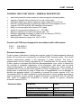
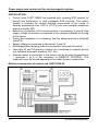
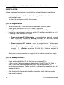
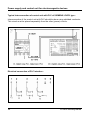
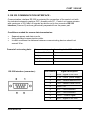
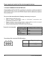
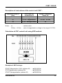
CUET 2 500 W
Power supply and control unit
for electromagnetic devices
Instruction manual
Power supply and control unit for electromagnetic devices
Copyright © 2002-2005
ATHEA Microsystems ®
Contents of this document are spiritual property of ATHEA Microsystems Company.
Without a former written consent of ATHEA Microsystems Company no part can be
copied or multiplied in any possible way (printing, photocopy, microfilm or any other
way), placed in the information system or transmitted in another form or by any other
means.
ATHEA Microsystems Company cannot assume any legal responsibility nor provide
any guarantee against using of false information with its following consequences.
Claims to compensation based on modifications, mistakes or omissions are
impossible in principle.
ATHEA Microsystems Company reserves its right to modify and improve the product
described in this user manual anytime without previous notice.
All registered or other trademarks used in this user manual are the property of their
owners. By mentioning them no property rights ensuing from them are challenged.
ATHEA Microsystems is the registered trademark – Office of Industrial Property, trade
mark No.249691.
4
ATHEA Microsystems
CUET 2 500 W
CONTENTS:
Power supply and control unit CUET 2500 W – general description …..…………..
Standards …..…..…………………..………………….…………………………………
Technical data ..…………………………………………………….……………………
Installation ………………………………………………………………………………..
Remote control - description of control elements ……...………………………….
- connection of remote control with control unit CUET 2500 ….
- electric connection of remote control …………………………..
Manipulation - magnetization cycle ………………………………………………….
- demagnetization cycle ……………………………………………….
CUE, CUET, CFR, CUR control units …………………………………………………
CUET control unit – operating controls descriptions …………...……………………
Settings - setting up of maximal chucking power …………………………………
- setting up of minimal chucking power …………………….……………
- setting up of machine blocking ………………………………………….
- description of DIP switch ………………………………………………...
Software upgrading of CUET control unit ……………………………………………..
Upgrading possibilities - Datamodulu 2k …………………………………………..
- MagnetEdit Demo operating software …………………
- Hyperterminal - Win 95,98,ME,XP .……………………
Communication interfaces of CUET control unit – overview …………..……………
PLC interface
- description of communication interface ………………………..
- recommended connection of control unit with PLC SIEMENS
LOGO! type ………………………………………………………...
- electric wiring of communication interface …………………….
RS 232 interface - description of communication interface ………………………..
- unidirectional connection of control unit with PLC SIEMENS
SIMATIC, UNITRONICS type, etc ……………………………….
- bidirectional connection of control unit with PLC SIEMENS
SIMATIC, UNITRONICS type, etc ……………………………….
RS 485 interface - description of communication interface ………………………..
- unidirectional connection of control unit with PLC SIEMENS
SIMATIC, UNITRONICS type, etc ……………………………….
- bidirectional connection of control unit with PLC SIEMENS
SIMATIC, UNITRONICS type, etc ……………………………….
Instruction set of control unit ………………………………………………….………..
Description of transmitting report ………………………………………………………
www.athea.cz
5
5
5
6
7
7
7
8
8
9
10
11
11
12
13
14
14
15
18
19
19
20
20
21
22
23
24
25
25
26
26
5
Power supply and control unit for electromagnetic devices
Mechanical version of CUET 2500 W operation system ….………………………...
Version with IP 54 protection - external dimensions ……………………………….
- fixing openings …………………………………….
Version with IP 00 protection - external dimensions ……………………………….
- fixing openings …………………………………….
Equipment of control system …………………………………………………………...
Warranty – guarantee conditions ………………………………………………………
Technical support ………………………………………………………………………..
6
28
28
29
29
29
30
31
31
ATHEA Microsystems
CUET 2 500 W
CONTROL UNIT CUET 2500 W – GENERAL DESCRIPTION
•
•
•
•
•
•
•
•
•
•
•
small and powerful control system for electromagnetic clamping plates
support of parallel interconnection of up to 8 control units
automatic adjusting to power frequency within range 50 Hz to 60 Hz
detection of disconnection of incoming conductor to the magnetic chuck
support of RS 232 and RS 485 industrial concentrators
ability to communicate with common PLC types
speed of communication between 1,2 – 33,6 kBd
galvanic separation of control and power part 1 kV
software upgrading (firmware) of control unit via Internet (TCP/IP)
signalling LED – Power, TxD/RxD, Error
working temperature range from -20°C to 70°C
Control unit CUE was designed in accordance with valid norms:
E.M.C. : EN 50081-2
L.V.D. : EN 61010-1
General description:
Control system is suitable for feeding and impulse control of electromagnetic clamping
plates. All functions are controlled by an efficient RISC microprocessor. The control
system automatically adapts to the frequency of power network. The level of
magnetization can be fluently regulated by P1 potentiometer on the remote control.
Control system is equipped with effective demagnetization cycle, which is inteded for
the removal of remanent magnetism of the workpiece, and which can be easily
removed afterwards. For enhancement of manipulation safety, the control system is
supplied with security contact which signals low level of magnization – but you should
always bear in mind that by using of lower level of magnetization it is not possible to
achieve the specified safety. It si possible to connect the control system to PC via
concentrator RS 232, which enables to modify features of control system according to
client`s demands. Control system supports industrial concentrators RS 232 and RS
485, which is intended for connection of control system to superior industrial
automatic machine (PLC).
Technical data:
www.athea.cz
Parameter
Supply voltage
Tolerance of supply voltage
Supply current at no load
Max. permanent output current
Working temperature range
Value
400 V AC / 50 - 60 Hz
±10 %
50 mA
22 A
-20ºC to +70ºC
7
Power supply and control unit for electromagnetic devices
INSTALLATION :
•
•
•
•
•
•
•
Control units CUET 2500W are supplied with covering IP00 version for
placing into distributors, or with increased IP54 covering. The control
system is intended for normal working environment in the range of
working temperature from -20°C to +70°C in non-cond ensation maximum
relative humidity 90%.
Before the connection of the control system it is necessary to check if the
supply voltage of network corresponds to the voltage indicated on the tag
of the device.
During the installation it is necessary that the safety terminal is attached
to the PE.
Supply voltage is connected to terminals L1 and L2.
Electromagnetic clamping plate is connected to terminals 46 and 47.
Terminals 23 and 24 (security contact) are connected to superior device
(e.g.industrial automatic machine PLC, etc.)
Remote control is connected to the control unit by 8-cored screened wire
– terminals 1 to 9 of the connector of REMOTE CONTROL. This
conductor must be placed separately from other (power) conductions.
Electrical connection of control unit CUET 2500 W :
8
ATHEA Microsystems
CUET 2 500 W
REMOTE CONTROL :
Operating controls description :
P1 – potentiometer for setting up of
chucking power level of magnetization
S1 – green illuminated pushbutton of
magnetisation
S2 - white illuminated pushbutton of
demagnetisation
Interconnection of remote control with the CUET control unit :
The remote control is connected to the control unit by 8-cored screened wire –
terminals 1 to 9 of the connector of the Remote Control. This conductor must be
placed separately from other (power) conductions.
Electrical connection :
Wire label
Wire
significance
Wire
color
1
Shielding
Black
2
P1/1
Green
3
P1/2
Yellow
4
P1/3
Brown
5
+12V DC
Grey
6
S1
White
7
S2
Red
8
S1 – LED
Blau
9
S2 - LED
Pink
www.athea.cz
9
Power supply and control unit for electromagnetic devices
MANIPULATION :
Before gripping of workpiece it is suitable to proceed following operations:
•
•
To clean workpiece and the surface of magnetic fixture and to ensure
good contact area
To place the workpiece on the fixture area
Cycle of magnetization :
•
•
•
•
•
Set potentiometer P1 into position of requisited chucking power.
Press green pushbutton S1 for 0,5 s. as a minimum
During the magnetization the green switch S1 is constantly on.
During the magnetization the green switch S1 is either constantly on or it
is flashing in the intervals of 0,5sec.
Green indicator S1 illuminates – magnetization passed through
well. Protecting contact is locked (terminals 23 and 24), which
means, that you start to tool the fastened subject.
Green indicator S1 flashes – error of magnetization. That means
that magnetic fixture was magnetized by lower level of magnetization
than setting value of trimer P2 – safety of operation level. Safety
contact is off-state (terminals 23 and 24) – fastened subject is
forbidden to tool.
After finishing of magnetization the magnetic chuck is disconnected from supply
network.
Cycle of demagnetization :
•
•
Press white pushbutton S2 for the time of minimum 0,5 s.
In the course of demagnetization the indicator lights S1 and S2 flash in
turns. In the end of demagnetization cycle the white indicator S2
illuminates permanently. Safety contact is unbraced for the whole time of
demagnetization.
•
After finishing of demagnetization the magnetic chuck is disconnected
from supply network.
10
ATHEA Microsystems
CUET 2 500 W
CONTROL UNITS CUE, CUET, CFR A CUR :
Control units CUE(T), CFR and CUR are customer‘s industrial automatic machines,
which were developed in accord with the newest requirements of industry and norms.
The control units are suitable for the phase control of magnetization and
demagnetization of magnetic chucks.
Classification of the control units:
CUE – control unit for electromagnetic chucks without a transformer – up to the output
power max. 1500W - it is possible to continuously regulate the clamping power by the
P1 potentiometer on the remote control.
CUET – control unit for electromagnetic chucks with a transformer – for the output
power between 2 500W - 25 000W - it is possible to continuously regulate the
clamping power by the P1 potentiometer on the remote control.
CFR – control unit for electropermanent magnetic chucks intended for milling regime
– the clamping power is preset by the producer on the maximum.
CUR – control unit for electropermanent magnetic chucks intended for grinding
regime - it is possible to continuously regulate the clamping power by the P1
potentiometer on the remote control.
CONTROL UNIT CUE (CUET, CFR AND CUR):
www.athea.cz
11
Power supply and control unit for electromagnetic devices
DESCRIPTION OF CONTROL UNITS :
12
ATHEA Microsystems
CUET 2 500 W
SETTING UP OF CONTROL UNIT :
Warning :
During the installation of control system which is
alive it is necessary to work in accordance with valid
ČSN (EN) about work with alive voltage.
On the front panel of the control unit the minimum (P3) and the maximum (P2) of
magnetization voltage can be set by using P4 potentiometer we can set the level of
security treshold.
If the control unit is operated by PLC it is possible, by using configurational DIP
switch, to set on the front panel:
Control unit address
Communication speed
Communication type
RS 485 terminator
-
up to 8 control units can parallelly work on RS 485 bus.
it can be set in the range between 1,2kBd and 33,6kBd.
choice between communication RS 232 or RS 485.
control unit is equipped with internal terminating resistor
150Ω.
Setting up of maximum clamping power :
Maximum clamping power can be set by P2 potentiometer on the front panel of the
control unit as follows:
•
•
•
Set P1 potentiometer on the remote control into the position of maximum
magnetization.
By turning P2 potentiometer clockwise the level of maximum magnetization is
increasing.
By turning P2 potentiometer anti-clockwise the level of maximum magnetization
is decreasing.
Setting up of minimum clamping power :
Minimum clamping power can be set by P3 potentiometer on the front panel of the
control unit as follows:
•
•
•
Set P1 potentiometer on the remote control into the position of minimum
magnetization.
By turning P3 potentiometer clockwise the level of minimum magnetization is
increasing.
By turning P3 potentiometer anti-clockwise the level of minimum magnetization is
decreasing.
www.athea.cz
13
Power supply and control unit for electromagnetic devices
Setting up of machine blocking :
Blocking machine relay (terminals 23 and 24) switches when the minimum
clamping power is achieved.
•
•
If the clamping power is higher than security treshold level – contacts of
blocking machine relay will clasp.
If the clamping power is lower than security treshold level – contacts of
blocking machine relay will unclasp.
Security treshold level can be set by P4 trimer on the front panel of the
control unit as follows:
•
•
By turning the P4 trimer clockwise the security treshold level is
increasing.
By turning the P4 trimer anti-clockwise the security treshold level is
decreasing.
Blocking machine relay is also unclasped in following cases:
•
•
•
•
After the connection of control system to feeding.
During demagnetization cycle.
After the disconnection of feeding voltage.
When the incoming conductor is disconnected to the electromagnetic
chuck.
Maximum switched current by relay contacts: 5A AC/DC
Maximum switched voltage by relay contacts: 230 V AC/DC
14
ATHEA Microsystems
CUET 2 500 W
Setting-up of configurational switch (DIP switch):
If the control unit is subordinated to the industrial automatic machine PLC, it is
possible, with the change of DIP switch, to modify the qualities of the control unit. The
DIP switch is intended to optimize the communication of the control unit with the
superior PLC. Setting-up of the switch should be done with the disconnected feeding
voltage (switched-off state).
If the control unit is not connected to the superior PLC (it is controlled only by the
remote control), it is not necessary to set up the DIP switch and constituent switches
can be in any position.
Fig. 1 -
Setting up of the address of the control system:
- if several control units are parallelly connected to
one bus, the superior industrial automatic machine
PLC has a different access to each control unit.
Important: if there are more control units
connected to one bus, it is necessary to assign a
different address to each of them.
Fig. 2 -
Setting up of communication speed :
- the control unit supports four standard
communication speeds. Setting up of the
communication speed is common for all types of
favoured bus.
Fig. 3 -
Parallel interconnection of control units :
- up to 8 control units can be parallelly interconnected through the interface RS 232 or RS 485.
Fig. 4 -
Type of communication :
RS 232 – intended for connection to PC or PLC
RS 485 – intended for connection to PC or PLC
Fig. 5 -
Terminating resistor 150Ω:
- possibility of connection (disconnection) of the
internal resistor.
www.athea.cz
15
Power supply and control unit for electromagnetic devices
SOFTWARE UPGRADING OF THE CONTROL UNIT VIA DATAMODULE
2K :
Datamodul – memory in which all information
needed for the activity of the control unit is saved.
Information saved in Datamodul can be replaced to the control unit in the following
way:
•
•
•
Turn off the control system.
Insert Datamodule into the connector RS 232 Interface according to the picture.
Turn on the control system.
During the data transmission from Datamodule into to control unit the yellow light
LED-TxD / RxD which signalises the data transmission is switched on. The control
unit programmed in this way will save its data even after the disconnection of feeding
voltage in its internal EEPROM memory – after the finishing of the programme cycle it
is suitable to take the Datamodule out of the connector.
Software upgrading of
the control unit via
Datamodule 2k :
Insert
Datamodule
into the connector RS
232 Interface
16
ATHEA Microsystems
CUET 2 500 W
SOFTWARE UPGRADING OF THE CONTROL UNIT VIA MAGNETEDIT
DEMO OPERATING PROGRAMME :
Control system can be connected via RS 232 bus to the PC, which enables
modification of the qualities of the control system according to the customer’s
demands.Control system communicates with the PC using serial port COM 1 to COM
4. Before connecting the control system to the PC it is necessary to install MagnetEdit
Demo operating programme. This software is assigned for operating systems such as
Win 95, 98, ME and XP and is common to all control systems CUE, CUET, CFR and
CUR.
MagnetEdit Software (full version) can be used for setting up of :
•
•
•
•
•
Number of sections of magnetic chuck.
Magnetisation voltage.
Number of magnetisation impulses.
Demagnetisation process.
Other (service) settings – communication between parallelly connected control
systems, additional sensors (current transformers, thermistors, hall probes), heat
protection, current protection, etc.
All settings can be saved in database file (*.dbf file) or in Datamodule 2k.
Before interconnection of control unit to the PC it is necessary to carry out :
•
•
•
•
Choice of free communication port COM 1 to COM 4 in MagnetEdit programme.
Setting up of RS 232 communication type using switch (DIP switch) – SW7 on
the front panel of the control unit.
Choice of communication speed using switch (DIP switch) – SW4 and SW5.
Control unit communication speed must be in compliance with the communication
speed set in MagentEdit operating programme.
Interconnection of control unit and PC by using original communication cable.
Any other interconnection can lead to damage of the computer or control unit.
It is recommended to use galvanic separation of serial computer port.
www.athea.cz
17
Power supply and control unit for electromagnetic devices
MagnetEdit Demo operating software :
MagnetEdit Demo software is provided with all control systems of the type
CUE, CUET, CFR and CUR. Before you start to install and use MagnetEdit
software, please check all the necessary components according to the
following list. In case of any discrepancy with the list, or if any item is
damaged (e.g. illegible installation CD-ROM), please contact your supplier.
List of equipment of control system CUET 2500 W :
•
•
•
User manual in Czech or English version.
Communication cable for connection of control unit CUE to PC.
Datamodule 2k
Recommended requirements for the control PC :
•
•
•
•
•
Pentium processor 100 MHz and more
32 MB of free RAM
1 x CD-ROM
Hard disc with free capacity of 10 MB
One serial communication port COM.
Installation of MagnetEdit Demo software :
Start the installation programme Setup.exe from the enclosed CD and follow the
instructions.
18
ATHEA Microsystems
CUET 2 500 W
Programming procedure of control unit :
•
•
•
•
•
•
Start MagnetEdit Demo operating software.
Choose free communication port COM 1 to COM 4.
Choose communication speed between 1,2 and 33,6 kBd, which is the same as
the communication speed set by DIP switch on the front panel of control unit.
From the menu open Type of control system and choose an indication of
connected control unit or press the button Autodetection.
From the menu open Setting of control system (magnetic chuck type) and
choose an indication of magnetic chuck connected to the control system.
Press the button Program the control system. After termination of programming
cycle the reset of the control unit will be automatically carried out.
MagnetEdit Demo operating software :
www.athea.cz
19
Power supply and control unit for electromagnetic devices
SOFTWARE UPGRADING OF CONTROL UNIT VIA HYPERTERMINAL:
It is possible to reprogram the control units CUE, CUET, CFR and CUR via the
communication programme Hyperterminal, which is integral part of all operating
systems such as Windows 95, 95, ME and XP. Hyperterminal programme is
standardly placed in the menu START-PROGRAMMES-ACCESSORIESCOMMUNICATION-HYPERTERMINAL.
Programming procedure of control unit CUE (CUET, CFR and CUR):
•
•
•
•
•
Request TxData.ht and TxData.txt files from the supplier.
Open TxData.ht file in Hyperterminal programme.
If necessary, change the communication port COM 1 to COM 4 in the menu FILE
– PROPERTIES – CONNECT here choose free communication port.
Interconnect control unit and the PC via the original communication cable.
Program the control unit: in the menu TRANSFER – SEND TEXT FILE – choose
TxData.txt file and the programming cycle will be started.
Hyperterminal software :
20
ATHEA Microsystems
CUET 2 500 W
1. PLC INTERFACE
This communication interface is intended for the simplest industrial automatic
machines PLC, which are not equipped with the communication channel UART (e.g.
SIEMENS LOGO!). All the interface signals are taken out to the clips 1 to 6 of the
connector PLC Interface and are galvanically (optically) separated from the control
unit. PLC interface requires external feeding ranging from 5 to 30 V DC. All outputs
are secured against short circuit by internal resistors.
Description of the connector PLC interface :
Terminal
marking
Signal
marking
1
+U
2
MAG
Starting of magnetisation
3
DEM
Starting of demagnetisation
4
BUSY
Activity indication
5
GND
0V DC
6
N.C.
Not connected
Signal description
Supply voltage + 5 až 30V DC
Description of individual signals of PLC interface :
+U
Terminal for external supply voltage + 5 až 30V DC
MAG
GND
Control impuls terminal for magnetisation of magnetic chuck.
Recommended length of control impuls is min 0,5 sec. During
the whole process of magnetisation the BUSY signal is
generated by the control unit.
Control impuls terminal for demagnetisation of magnetic
chuck. Recommended length of control impuls is min 0,5 sec.
During the whole process of magnetisation the BUSY signal is
generated by the control unit.
Signalization of control unit activity. The signal is current
limited to 50mA.
0V DC.
N.C.
Not connected
DEM
BUSY
www.athea.cz
21
Power supply and control unit for electromagnetic devices
Typical interconnection of control unit with PLC of SIEMENS LOGO! type :
Interconnection of the control unit with PLC should be done using shielded conductor.
This circuit must be placed separatelly from the other (power) circuits.
Electrical connection of PLC interface :
22
ATHEA Microsystems
CUET 2 500 W
2. RS 232 COMMUNICATION INTERFACE :
Communication interface RS 232 is projected for connection of the control unit with
the industrial automatic machine PLC, possibly with PC. Control unit communicates
with maximum of 33,6 kBd. All signals are driven out to the connector RS 232
Interface (Cannon 9) and are galvanically separated from the power part.
Conditions needed for secure data transmission :
•
•
•
Separate power and data circuits.
Using shielded communication cable.
In ideal conditions the distance between communicating devices should not
exceed 30 m.
Format of outcoming data :
Communicat. speed
According to the DIP switch 4,5
Number of data bits
8
Parity
None
Stop-bits
1
Data flow control
None
RS 232 Interface (connector):
Pin number
1
www.athea.cz
Signal description
SDA – signal of I2C bus
2
+ 5V – intern. power supply
3
RxD – receive data RS 232
4
TxD – transmit data RS232
5
GND – 0V
6
N.C. – not connected
7
N.C. – not connected
8
TEST – control signal
9
SCL – signal of I2C bus
23
Power supply and control unit for electromagnetic devices
Typical unidirectional interconnection of the control unit with PLC of SIEMENS
SIMATIC CPU 22x type :
PLC industrial automatic machine equipped by Freeport (free programmable UART
serial link with supported ASCII record) is possible to interconnect to the control unit
CUE with the help of 2-venous shielded conductor. The signals RxD and GND are
used for data transmitting – all other signals must be left unconnected.
For secure data transmittion the following is necessary to carry out :
•
•
•
•
•
•
Interconnection of TxD signal of PLC automatic machine to the RxD signal of
CUET control unit.
Interconnection of GND signal of PLC automatic machine with the GND signal of
CUET control unit.
Setting up of communication to RS232 – DIPswitch SW7=Off.
Setting up of parallel interconnection of control units – DIPswitch SW6=Off.
Setting up of communication speed – DIP switch SW4 to SW5.
Setting up of control unit address – DIP switch SW1 to SW3.
Description of transmitting report RS 232 :
Control unit continuously monitors serial data on the input RxD. Incoming data on this
input must be in ASCII format in hexadecimal form. When the control unit receives
data in the valid format and with the right address of the target device, the requested
order will be carried out.
24
ATHEA Microsystems
CUET 2 500 W
Typical bidirectional interconnection of the control unit with PLC of SIEMENS
SIMATIC CPU 22x type :
PLC industrial automatic machines equipped by Freeport (free programmable serial
link UART with supported record ASCII) is possible to interconnect to the control unit
CUET with the help of 3-venous shielded conductor. The signals TxD, RxD and GND
are used for data transmitting – all other signals must be left unconnected.
For secure data transmittion the following is necessary to carry out :
•
•
•
•
•
•
•
Interconnection of TxD signal of PLC automatic machine to the RxD signal of
CUET control unit.
Interconnection of RxD signal of PLC automatic machine with TxD signal of
CUET control unit.
Interconnection of GND signal of PLC automatic machine with GND signal of
CUET control unit.
Setting up of communication to RS232 – DIPswitch SW7=Off.
Setting up of parallel interconnection of control units – DIPswitch SW6=On.
Setting up of communication speed – DIP switch SW4 to SW5.
Setting up of control unit address – DIP switch SW1 to SW3.
Description of transmitting report RS 232 :
Control unit continuously monitors serial data on the input RxD. Incoming data on this
input must be in ASCII format in hexadecimal form. When the control unit receives
data in the valid format and with the right address of the target device, the requested
order will be carried out. After finishing of the required operation (magnetisation,
demagnetisation) the control unit will send off a message to the superior PLC.
www.athea.cz
25
Power supply and control unit for electromagnetic devices
3. RS 485 COMMUNICATION INTERFACE :
Communication interface RS 485 is projected for connection of control unit with the
industrial RS 485 bus. Control unit communicates at maximum speed of 33,6 kBd. A+
and A- signals are driven out to the RS 485 connector and are galvanically separated
from the power part.
For secure data transmittion the following is necessary to carry out :
•
•
•
•
Separate power and data circuits.
2
Using of twisted communication cable of 0,35-0,8mm cross-section with
characteristic impedance of 120Ω.
Distance between communicating devices in ideal conditions should not exceed
1600 m (concerns conductors with capacity of 65pF/m).
Using of terminating resistor 150Ω (just in case of necessity).
Format of outcoming data :
Communicat. speed
According to the DIP switch 4,5
Number of data bits
8
Parity
None
Stop-bits
1
Data flow control
None
Connecting of the connector RS 485 Interface :
26
Marking
Signal description
A+
A+ signal
A-
A- signal
0V
0 V DC
ATHEA Microsystems
CUET 2 500 W
Typical interconnection of control unit to the RS 485 bus :
Control unit CUET is interconnected to the RS 485 bus using 2- cored twisted
conductor. For data transmittion A+ and A- signals are used. Oll other signals must be
left unconnected.
For secure data transmission the following is necessary to carry out :
•
•
•
•
•
•
•
Connection of A+ signal to the RS 485 concentrator.
Connection of A- signal to the RS 485 concentrator.
Setting up of communication on RS 485 – DIP switch SW7 = On.
Setting up of parallel interconnection of control units – DIP switch SW6 = Off.
Setting up of communication speed – DIP switch SW4 to SW5.
Setting up control unit address – DIP switch SW1 to SW3.
Using of terminating resistor 150Ω (just in case of need) – DIP switch SW7.
Description of transmission report RS 485 :
Control unit continuously monitors serial data on the A+ and A- inputs (concentrator is
in a state of high impedance). Incoming data on this inputs must be in ASCII format in
hexadecimal form. When the control unit receives data in the valid format and with the
right address of the target device, the requested instruction will be carried out. After
finishing of the required operation the control unit will send off a message to the
superior PLC and re-initiates the concentrator to the state of high impedance.
www.athea.cz
27
Power supply and control unit for electromagnetic devices
INSTRUCTION SET OF THE CONTROL UNIT CUET
Description of the transmission report :
All functions of control units can be operated via asynchronous serial line (UART),
which is common to RS 232 or RS 485 bus. All transmitted data must be in
hexadecimal form coded in compliance with the international standard of ASCII.
Control unit constantly monitors serial data on the RxD input, eventually A+ and A-.
When the control unit receives data in valid format and with the right address of the
target device, the requested instruction will be carried out. The control unit will confirm
the accomplishing of the instruction by sending off the same message which it
received. This is not true in parallel connection of control units, in which the control
unit only receives the outcoming address. This property enables the concatenation of
control units, in which one control unit activates the following control unit.
Each outgoing message always starts with sending off the STX character. Then
ADDR follows (target address of the control unit), C0 (required instruction), V0 (value
related to the required instruction) and CRC (control total XOR). The ETX
characteristic is sent out as the last one and terminates the transmittion.
The processing of the required instruction starts at the moment of reception of ETX
characteristic. Required instruction will not be carried out unless the received address
ADDR and the address set on the front panel of the control unit (DIP switch) are in
agreement. If the received address is not in agreement, then the control unit will
ignore the whole received message.
Format of the received data :
Transmitted data
STX
ADDR
C0
V0
CRC
ETX
Hex format
02
0x
0x
xx
xx
03
ASCII character
☻
xx
xx
xx
xx
♥
Význam použitých zkratek :
Zkratka
STX
ADDR
C0
V0
CRC
ETX
28
Popis
Start of transmitting
Address of target device
Requested instruction
Value related to requested instruction
CRC of all previous values (except STX)
End of transmitting
ATHEA Microsystems
CUET 2 500 W
Description of instructions of the control unit CUET :
Instruction code C0
(Hex)
Notes:
Description of
instruction C0
Range of permitted
values V0
00
STOP magnetisation
xx
01
START magnetisation
00 Hex – 64 Hex
02
START demagnetisation
xx
xx
- random value
00 Hex – 64 Hex
- value of magnetisation voltage in the range of 0-100%
Calculation of CRC control total using XOR method :
Examples of ASCII strings :
START Magnetisation 100% (address 00) : ☻00016403 ♥
STOP Magnetisation (address 00)
: ☻00000000 ♥
START Demagnetisation (address 00)
: ☻00020002 ♥
www.athea.cz
29
Power supply and control unit for electromagnetic devices
MECHANICAL CONSTRUCTION OF CONTROL SYSTEM CUET 2500W
Technical characteristics:
•
•
•
•
•
•
IP 54 cover according to EN 60 529
Mechanical resistance according to EN 50 102- IK 10
Certification – LCIE, UL, DNV, BV
Construction – closed welded box, the front profile in the form of roof gutter made
from the double sheet gauge, which secures high consistency of the frame and
impermeability of the door
Door with turning possibility and with the opening angle of 130°
Colour- polyester powdered composition in the colour shade RAL 7032
CUET 2500 W enclosure sizes :
* all dimensions in mm
30
ATHEA Microsystems
CUET 2 500 W
CUET 2500 W – version with IP 54 protection
* all dimensions in mm
CUET 2500 W – version with IP 00 protection
* all dimensions in mm
www.athea.cz
31
Power supply and control unit for electromagnetic devices
CONTROL SYSTEM EQUIPMENT:
Together with the CUET 2500 W control system the following equipment is supplied.
In case of any discrepancy with this list, or if any item is damaged (e.g. illegible
installation CD-ROM), please contact your supplier.
•
•
•
32
User manual in Czech or English version..
Communication cable for connection of CUET control unit to PC.
Datamodule 2k.
ATHEA Microsystems
CUET 2 500 W
WARANTY
Guarantee conditions
There is a 12-month-guarantee for the given product since the day of purchase.
During this period the supplier agrees to repair or exchange free of charge all parts
with defects obstructing their proper use according to the producer instructions. This
concerns parts which have latent defects or which do not correspond by their
configuration with the product documentation and technical conditions of the
product. The transport costs are to be covered by the customer.
The guarantee does not apply to :
•
•
•
•
defects caused by improper use of product, e.g. incorrect connection to the
network or to the signal sources, incorrect connection of circuits, overloading or
interference with the product.
defects caused by external influences, e.g. damage caused by transport, crash,
heat, water, aggressive substances, etc.
signal lights, control elements, circuit breaker and power semiconductor
elements (thyristors, triacks, diodes, etc.)
eventual idle time of the machine as a result of the defect of the product.
We hope that you will be fully satisfied
with our products.
Date :
S.N. :
Stamp of supplier:
Guarantee and post-guarantee
service is provided by:
Sign. :
Martin Valeš
Tiskárenská 433
672 01 Moravský Krumlov
Czech Republic
Tel.: +420 605 892 095
E-mail : [email protected]
Internet : www.athea.cz
www.athea.cz
33