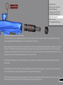
1
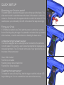
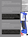
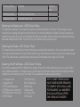
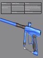
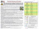
OWNERS MANUAL
Droid Owners Manual
V1.02
Copyright Mac Developments Pty. Ltd. 2008
All rights reserved
No part of this document may be copied or reproduced in any form or by any means without the
prior written consent of Mac Developments Pty. Ltd.
Notice is hereby given that this manual is part of the article owned in whole by Mac Developments
Pty. Ltd., known as indicated in this manual and drawings. All rights of manufacture and reproduction of such articles or any part thereof are reserved by Mac Developments Pty Ltd. Neither said
article nor any part thereof may be manufactured or reproduced without the written authorization
from Mac Developments Pty. Ltd. All proprietary rights and information are the sole property of
Mac Developments Pty. Ltd.
MacDev, Cyborg, Conquest, Gladiator, MatchStick, Droid and Sonic are all registered trademarks
of Mac Developments Pty Ltd.
Statement of Liability
Mac Developments Pty. Ltd. Makes no warranties with respect to this documentation and disclaims any implied warranties of merchantability or fitness for a particular purpose. The information in this document is subject to change without notice. Mac Developments Pty. Ltd. assumes
no responsibility for its resale or safe handling. Mac Developments Pty. Ltd. assumes no responsibility for physical injury or property damage resulting from its use.
Warranty
Contents
The Droid marker is covered by the MacDev 12 month warranty against Know your Droid
Quick Setup
manufacturing defects. The Droid is guaranteed free of manufacturing Using your Droid
defects for a period of twelve (12) consecutive months beginning immedi- Advanced Setup
ately after purchase from a registered retailer. The solenoid is warranted Maintenance
for a period of thirty (30) days after the date of purchase. If a manufactur- Parts List
ing defect is detected, the defective part will be either repaired or replaced Troubleshooting
at no cost to the owner. The Droid warranty is not transferrable in the
event of 2nd hand sales - the warranty may only be claimed by the original
retail purchaser. The Droid warranty does not cover damage due to theft, misadventure or operator error/abuse.
To make a successful warranty claim, the owner must produce their warranty card and proof of
purchase.
Caution!
This is not a toy. Misuse may cause serious injury or death. Eye protection designed
specifically for paintball must be worn by user and persons within range. Recommend
18 years or older to purchase. Persons under 18 must have adult supervision.
READ OWNER’S MANUAL BEFORE USING.
2
CONTENTS
Know your Droid (Page 5)
All users should read this section to learn the parts of your Droid and their names.
Quick Setup (page 7)
Learn how to set your Droid up for use the first time.
Switching your Droid on and off
Firing your Droid
Understanding the beam sensor
Disabling the beam sensor
Installing a preset air system
Turning the air on and off
Using a loader with your Droid
Installing a loader onto your Droid
Removing your loader
Using your Droid (Page 10)
Essential reading on how to use your Droid marker.
Adjusting the velocity
Adjusting the trigger
Replacing the battery
Advanced Setup (Page 11)
A section for those who are comfortable with making fine adjustments to the Droid marker.
About the tourney lock
Programming the Droid Software
Setting the Debounce
Setting the Dwell
Setting the Fire Mode
Setting the Rate of Fire (ROF)
Setting the Loader Delay
Setting the Anti Mechanical Bounce (AMB)
Setting the Anti Bolt Stick (ABS)
Setting the Ramp Start
Setting the Cycle Filter
Setting the Eye Mode
Setting the Bolt Tracking Delay
Setting the Test Mode Dwell
Resetting the Software
Contents
Know your Droid
Quick Setup
Using your Droid
Advanced Setup
Maintenance
Parts List
Troubleshooting
Maintenance (Page 17)
Maintaining your purchase is essential to long term product satisfaction.
Basic cleaning
Maintaining the drive train
Maintaining the inline regulator
Parts List (Page 21)
An exploded view of your Droid with parts labelled.
Troubleshooting (Page 25)
Solving common difficulties.
Common problems and solutions
Technical assistance
Parts and Accessories
Enhance the Droid experience with a range of genuine accessories and spare parts.
4
KNOW YOUR DROID
3
2
1
18
4
6
5
17
7
16
8
15
9
14
13
12
11
10
Your Droid marker has been CNC milled from a solid billet of 6061 aircraft
grade aluminium, representing the highest quality workmanship available in
aluminium manufacturing. The milling has been performed by a 3D surfacing
machine, with each marker taking many hours to produce.
Please take the time to learn the parts of your Droid, it will help you when reading this manual.
Contents
Know your Droid
Quick Setup
Using your Droid
Advanced Setup
Maintenance
Parts List
Troubleshooting
Numbered basic parts as shown in the figure on the left:
1. Matchstik 2 piece barrel
2. Feed clamp lever (used to affix your loader)
3. Feed clamp adjuster screw
4. Top locating screw (must be removed before disassembly of the drive train
5. Eye cover and screw (covering the beam sensor used to detect paintballs)
6. End cap
7. On/Off switch
8. Indicator LED
9. Wrap around grip (covering the battery and electronics)
10. Venting ASA (used to attach your preset air system)
11. Venting ASA on/off cap (used to turn the air on or off)
12. Straight push-fit hose fitting
13. Air hose
14. 90 degree swivel push-fit hose fitting
15. Velocity adjustment screw
16. Inline regulator (Gladiator reg)
17. Vertical ASA
18. Feed Tube
6
QUICK SETUP
Switching your Droid on and off
The on/off switch is located on the upper section of the rear of the frame. This
slide switch should be switched towards the barrel of the marker to switch the
marker on. Slide the switch the opposite direction to switch the marker off. Successful power up is indicated by the LED on the side of the wrap around grip.
Firing your Droid
If a Paintball is loaded in your Droid, and the power is switched on, you may
fire the Droid by pulling the trigger. If a paintball is not loaded, then you need to
either load one, or read the section below on disabling the beam sensor.
Understanding the beam sensor
Your Droid is equipped with a visible light sensor to determine if a paintball is
correctly loaded. This system is used to prevent accidental ball breakage due to misloaded paintballs. The LED indicator on the side of your grip will show you
the status of the beam sensor:
Ball
Loaded
Green: Ball is loaded
Red: Ball is not loaded
Flashing Orange: Sensor malfunction
Flashing Red: Sensor disabled
Disabling the beam sensor
To disable the sensor (for dry firing), hold the trigger in until the indicator LED
begins flashing red. You can re-enable the beam sensor the same way.
No Ball
Loaded
Installing a Preset Air System
Your MacDev Droid comes equipped with a high quality venting ASA (Air System Adaptor) that is designed for use with commercially available Air/Nitrogen
systems.
The venting ASA that is included with your Droid uses a screw cap to turn the
air from your preset system on or off. Before installing your preset air system,
you must unscrew the ASA cap by approximately 3 turns (do not unscrew it
further, as the cap can come off completely).
Contents
Know your Droid
Quick Setup
Using your Droid
Advanced Setup
Maintenance
Parts List
Troubleshooting
WHEN SCREWING YOUR AIR SYSTEM INTO THE ASA, THE
THREADS SHOULD BE LOOSE. IF AT ANY POINT THEY BECOME
TIGHT, DO NOT FORCE THE THREADS, THIS MAY CAUSE DAMAGE
TO YOUR SYSTEM OR YOUR DROID MARKER!
Once this is done, carefully screw your air system into the ASA until it stops.
Turning the air on and off
To pressurise your Droid marker, screw the ASA cap down until it stops. This
will depress the pin on the end of your air system and pressurise the marker
(provided you have sufficient air in your air system).
NOTE: WHEN YOU UNSCREW THE ASA CAP, YOUR MARKER USUALLY STORES ONE SHOT. POINT THE MARKER IN A SAFE DIRECTION AND FIRE OFF THAT SHOT BEFORE ENTERING A SAFE AREA.
8
Using a loader with your Droid
Your Droid Marker can operate using any commercially available loader.
The software and beam sensor will compensate for the speed of the hopper,
together ensuring that the marker fires as quickly as the loader allows.
All Droid markers are equipped with a cam lever clamping feed tube. This
system allows the easy installation and removal of your loader. You will need
to adjust the feed tube to suit the loader that you have.
Installing a loader onto your Droid
Open the cam lever as shown. This should allow your loader neck to fit into
the feed tube as shown. If your feed tube does not fit into the feed tube, then
you may have to loosen the adjustment screw slightly. Once your loader is
DO NOT OVER TIGHTEN YOUR FEED CLAMP! OVERTIGHTENING
MAY RESULT IN DAMAGE TO YOUR LOADER.
pushed all the way down into the feed tube, close the cam lever. If your loader
is loose, you may now tighten the adjustment screw (by turning clockwise) to
tighten the loader in place.
Removing your loader
Open the clamp by swinging the lever on its hinge. This will loosen the loader
and allow you to remove it easily. If it does not remove easily, then it means
that you have the clamp adjustment screw overtightened.
Insert of feed tubes and
loaders here
USING YOUR DROID
To get the most out of your Droid, make sure that you follow the instructions in
this section to ensure that the marker is adjusted correctly.
Adjusting the velocity
The velocity of the Droid is adjusted via an adjustment screw on your inline
regulator. To increase velocity, use a 3/32” allen key to turn the adjustment
screw anti clockwise. Always adjust your Droid gently and using a chronograph.
DO NOT ADJUST YOUR VELOCITY ABOVE 300FPS, AND ALWAYS
OBEY LOCAL LAWS AND REQUIREMENTS.
Contents
Know your Droid
Quick Setup
Using your Droid
Advanced Setup
Maintenance
Parts List
Troubleshooting
of velocity adjustment
Adjusting the trigger
Your Droid trigger has three adjustment screws, they are located in the front
face of the trigger in the following order from top to bottom:
- Pull tension
- Switch actuation point
- Pull length
You may easily adjust these three screws to personalise the feel of your trigger.
CAUTION! WHEN ADJUSTING THE SWITCH ACTUATION SCREW,
MAKE CERTAIN THAT YOU DO NOT ADJUST THE SCREW IN TOO
FAR, AS THIS MAY RESULT IN DAMAGE TO YOUR MICROSWITCH.
Replacing the battery
Lay your Droid on a table with the barrel pointing to your left and the feed tube
pointing away from you.
10
Pic
Remove the three screws that hold the wrap around grip on and peel the grip back to allow access to the
battery. Remove the old battery, and replace it with a new one. Only use high quality alkaline 9V batteries,
the best possible choice is to use a MacDev Militia PowerPack (type 6LR61).
CAUTION! WHEN REMOVING THE BATTERY, TAKE CARE NOT TO PULL ON THE WIRES CONNECTING IT TO YOUR BOARD.
Once your new battery is installed, ensure that all wires are in the grip cavity before replacing the wrap
around grip and fixing it in place using the three screws.
Advanced Setup
About the tourney lock
The Droid board is equipped with a tourney lock system. When the tourney lock system is activated, the gun
cannot be reprogrammed on the field - making it tournament legal.
DO NOT USE A SHARP OR METAL OBJECT ON THE TOURNEY LOCK BUTTON. DO NOT USE EXCESSIVE FORCE - THIS MAY CAUSE DAMAGE TO YOUR BOARD!
To use the tourney lock, you must remove the three screws holding the left hand side of the wrap around grip
on your frame. On the board, there is a small copper button. Use a q-tip or similar non metallic, blunt object
to hold this down. The board will flash red/green, and then end on either red or green. This ending colour
indicates the state of the tourney lock:
Red: Tourney lock on
Green: Tourney lock off
Once you have finished with the tourney lock, replace the wrap around grip and
screws before playing.
Contents
Know your Droid
Quick Setup
Using your Droid
Advanced Setup
Maintenance
Parts List
Troubleshooting
Programming the Droid Software
To program the board, turn the gun off. Hold down the trigger whilst turning the
gun on. The indicator light will turn white, continue to hold the trigger until it goes
blue (debounce register). Press the trigger once to advance to the next setting
as given below. When you have a setting you would like to change, hold the trigger until the indicator light goes out. Release the trigger, and the indicator light
will flash to show the current setting. Then when it goes out, input the new setting by the trigger and wait
for the indicator light to go solid again.
Register Summary Table
LED Colour
Setting
Default
Blue
Debounce (1/2ms increments)
10
Red
Dwell (1ms increments)
12
White
Fire mode
1 (semi)
Green
Max ROF - only used in capped and ramp
modes
5 (15bps)
Yellow
Loader delay (1/2ms increments)
2
Teal
Anti Mechanical Bounce
2
Purple
Anti Bolt Stick
3
Flickering Blue
Ramp Start (used on ramping fire modes)
5bps
Flickering Red
Cycle filter
2
12
Flickering White
Eye Mode
2 (forced
shot)
Flickering Green
Bolt Tracking Delay (ms)
10
Flickering Yellow
Test Mode Dwell (ms)
2
Setting the Debounce - LED Colour Blue
The debounce setting of your marker is used to control the amount of ”bounce” in your trigger. A very
low debounce setting will result in a lot of bounce. In some tournaments or fields, it will be necessary to
reduce the amount of bounce by increasing the debounce setting. Always increase the debounce slowly,
because settings higher than 15 will result in your marker feeling unresponsive.
Setting the Dwell - LED Colour Red
The dwell setting controls the amount of time that your solenoid is held open. A very low dwell will result
in very poor performance from your Droid, whilst a very high value will result in a very slow maximum rate
of fire. For best results, you should only operate your Droid dwell in the range of 12-16ms.
Setting the Fire Mode - LED Colour White
Your Droid is equipped with 12 different fire modes. These fire modes will allow you to use your Droid in
many different situations - tournament play, recreational and scenario. Always follow the rules and local
regulations when selecting your fire mode. The available fire modes are given below:
1 Uncapped semi
2 Capped semi
3 PSP Auto Response
4 PSP/Millenium mild ramp
5 PSP/Millenium max ramp
6 PSP Z-Burst
7 NXL Full Auto
8 Auto Response
9 Mild ramp
10 Max ramp
11 3 shot burst
12 Full auto
NOTE: SOME VERSIONS MAY
HAVE SOME MODES REMOVED
TO COMPLY WITH LOCAL LAWS.
FOR EXAMPLE, ALL MARKERS
SOLD IN AUSTRALIA OFFER
ONLY SEMI AUTO MODES.
Setting the Rate of Fire (ROF) - LED Colour Green
Your Droid can electronically limit its maximum ROF. This is required in some
tournaments or fields. In uncapped modes, the ROF will only be limited by the
speed of the gun and hopper. If you use a capped mode (like PSP or Millennium), the mode will obey the maximum ROF. The ROF is adjustable from 11bps
in 1/4bps increments (1=11, 2=11.25, 3=11.5 ... 26=uncapped).
Contents
Know your Droid
Quick Setup
Using your Droid
Advanced Setup
Maintenance
Parts List
Troubleshooting
Setting the Loader Delay
This is a small dwell included to allow the ball to settle into your marker breach
before firing. For a very fast loader, this may be set to 1, for slow hoppers it
should be higher. If your loader delay is set too low for your loader, then you may experience paintballs
breaking in the Droid breech.
Setting the Anti Mechanical Bounce (AMB)
Primarily, you should use the Debounce register to remove bounce from your Droid marker. However, if
you experience excessive bounce, it may be from a mechanical source. This AMB filter is designed to
remove excessive bounce, and it should be incremented slowly to remove bounce when bounce cannot
be removed using the Debounce register.
Setting the Anti Bolt Stick (ABS)
When your marker is idle for long periods, friction and settling effects can cause your bolt or other moving parts to be sticky. The ABS system is used to overcome this on the first shot by temporarily increasing the dwell setting. The ABS is adjustable from 1-10ms where the setting is the temporary increase in
dwell, and a setting of 1 removes the ABS completely.
Setting the Ramp Start
When using a ramp mode, this setting can be used to set the fire rate at which ramping starts – adjustable from 4-14bps. Current PSP rules require a minimum setting of 5bps, whilst current Millennium 14
rules require a minimum setting of 8bps.
Setting the Cycle Filter
Your software allows the buffering of a single shot in case you pull the trigger during a cycle. This filter
can be used to reduce the time allowed to buffer this shot. Adjustable from 1 (full buffer) to 10 full cycle
filter. Higher settings will reduce the amount of mechanical bounce in the marker, whilst low settings will
make the marker feel aggressive and responsive.
Setting the Eye Mode
Your Droid can utilise the beam sensor (eye) in different ways. This setting can be used to select which
way you would like to have the sensor used. The system can use a delayed mode, where if a ball is not
detected in the breech, a shot will be fired after a half second delay. This mode is useful if you are using
a sound activated loader, or if you would like your gun to indicate to you when you are out of paintballs.
Another option is the forced mode. In this mode, the marker will only fire if a ball is detected. However,
the user can force a shot to be fired by holding the trigger until the marker fires.
The beam sensor can also be used to test the speed of your Droid by watching the bolt during dry firing.
To allow this, your Droid has two test modes - test mode with full dwell, and test mode with adjusted
dwell. When fired in these modes, your Droid will report back to you the approximate speed achieved via
the colour of the indicator LED. The colours are given below:
To set your eye mode, use the following register settings:
red : less than 10bps
yellow : 10-15bps
green : 15-20bps
blue : 20-25bps
white : 25+bps.
The test mode with full dwell uses the same dwell that you are currently using with your marker, the test
mode with adjustable dwell allows you to conveniently change the test mode dwell without changing the
1 - delayed
2 - forced
3 - test mode with full dwell
4 - test mode with adjusted dwell
usual operating dwell of your marker. To adjust this dwell, use the last register
(Test mode dwell).
Setting the Bolt Tracking Delay
The bolt tracking delay is a parameter used to ensure that bolt tracking is working correctly. Do not adjust this unless you are advised by a MacDev tech.
Setting the Test Mode Dwell
The test mode dwell is used to adjust the dwell used when the user selects the
test mode with adjustable dwell in the eye mode register (Described above).
The user may adjust this setting from 1-30ms.
Contents
Know your Droid
Quick Setup
Using your Droid
Advanced Setup
Maintenance
Parts List
Troubleshooting
Resetting the Software
If required, the software may be reset to the
factory defaults. This is useful if the user has
made changes to the software settings that
result in malfunctions, the software may be
quickly and easily reset to default.
Before attempting to reset the board, you
must have the wrap around grip open on the
left hand side and be able to enter programming mode. If your board has the tourney lock
enabled, you will have to disable it before
continuing. For instructions on this see the
beginning of the Advanced Setup section.
To reset the board, first enter programming
16
mode (turn the Droid on with the trigger depressed). The indicator LED should now show blue (debounce
register). Use a q-tip or similar non metallic, blunt item to depress the tourney lock button as shown. Hold the
button for approximately 10 seconds until you see the indicator LED flash a rainbow of colours. The software
is now reset to default settings.
If you experience difficulties setting or resetting your software, please contact your closest MacDev tech for
advice.
Maintenance
If you take 10 minutes after every day of play to maintain your Droid, you will be rewarded with consistent
reliable performance.
You should perform basic cleaning after every day of play, and you should perform drive train and inline regulator maintenance after at least every 2 days of play. You can clean and maintain your Droid more often, it is
up to you.
When maintaining your Droid, use only MacDev accessories. Your Droid is packaged with an allen key set
and a small tub of MacDev Militia Lube, only use Militia Lube to lubricate your Droid.
Basic cleaning
After using your Droid, always clean old paint from the outside. Always clean your barrel using a barrel swab
to remove traces of dirt and paint. Use your barrel swab to clean the breech and feed tube in a similar way.
Your Droid internal parts are quite well protected and sealed. However, when not in use, dirt can get into the
marker and cause problems - so storage of your marker is just as important as cleaning. When storing your
marker, ensure that it is stored in a closed box or bag that is free of dirt, otherwise dirt may get into the venting ASA or breech.
Contents
Know your Droid
Quick Setup
Using your Droid
Advanced Setup
Maintenance
Parts List
Troubleshooting
Maintaining the drive train
The drive train is the hardest working part of your Droid. To work well, it should be cleaned and relubricated using the MacDev Militia Lube included with your Droid.
Before working on the drive train, ensure that your Droid is depressurised, switched off and has no paint
inside. To remove the drive train assembly, first you must remove the top locating screw. Then remove
the back cap, and use the short end of your allen key to hook the slots on the rear of the drive train. You
should then be able to pull the drive train out of your Droid.
Now that the drive train is out of the marker, you can put the marker body aside to concentrate on the
drive train.
Disassemble the drive train by unscrewing the keg, joiner and valve keg. You can now remove the bolt.
Unscrew the power tube cap and remove the power tube and valve.
All of the internal parts are now separated, so clean the old grease off them using a clean cloth, and
18
clean the old grease out of the keg and valve keg bores using a q-tip.
Use Militia Lube to lubricate the valve bore and valve o-rings. Slide the valve back into the valve bore.
Make certain that it is inserted the correct way - as shown.
Slide the power tube back into the valve keg and screw the retainer cap firmly over the end. Ensure that
the floating valve keg floating o-ring is in place, and screw the joiner into the valve keg.
Lubricate the keg bore, and the bolt switching o-rings, and then slide the bolt back into the keg.
Make sure that the keg floating o-ring is in place. Lubricate the power tube o-rings and slide the bolt and
keg over the power tube, and screw it over the joiner.
Lubricate the drive train outside o-rings, and align the keg locating slot carefully to the top of your Droid.
Slide the drive train into the Droid body without twisting it, until it stops.
Look down the locating hole to check the alignment of the locating hole with the locating slot on the keg.
If it is slightly misaligned, use a small allen key to push it into place through the locating hole. If it is very
badly misaligned, you may have to remove the drive train and begin again.
Once the drive train is correctly aligned, fix it in place using the top locating screw and seal the chamber
by replacing the back cap.
Your Drive train is now primed and ready for use. If your Droid does not work correctly after maintaining
the drive train, check that it is aligned, and reassembled correctly.
Maintaining the inline regulator
Your inline regulator (otherwise know as Gladiator reg), regulates the pressure from your air system
down to the pressure used to fire your Droid. It is very important that your inline regulator is working
well, if not, you may experience problems with velocity fluctuation or shootdown.
Before working on your Gladiator reg, make certain that the air supply is turned off (via the venting
ASA), and safely fire any gas out of the gun to ensure it does not have any residual pressure.
Remove the hose from the fitting in the bottom of the Gladiator reg - you do this
by pushing the collar in, whilst pulling the hose out. Once the hose is removed,
you can unscrew the Gladiator reg from your Droid. Put your Droid aside so that
you can concentrate on your Gladiator reg.
Unscrew the bottomworks from the topworks of the Gladiator reg. You should
be able to do this by hand, however, if you find it difficult, there is an allen hex
inside the topworks and flats that you can use for grip on the bottomworks.
Contents
Know your Droid
Quick Setup
Using your Droid
Advanced Setup
Maintenance
Parts List
Troubleshooting
Use an allen key from your tool set to push the internals out of the topworks. Disassemble the internals
as shown.
Use a clean cloth to wipe the old grease from the o-rings. Use a q-tip to clean the old grease from inside
the topworks bore.
Apply a thin film of grease to the shaft of the piston and the retainer o-rings before re-assembling the
internals. Use your finger or a q-tip to apply a thin film of grease to the topworks bore, and apply a generous film of grease to the piston o-ring before pushing the internals back into the Gladiator reg topworks.
Now use your clean cloth to remove any excess grease from the piston tip and clean the seat (the red
plastic part in the centre of the bottomworks. Screw the topworks and bottomworks back together. Make
certain that the Gladiator reg is screwed together firmly by hand. This will prevent it from unscrewing accidentally during play.
Re-assemble your Droid be attaching the Gladiator inline reg and hose. Push the hose in firmly until it
stops. Re-chronograph your Droid before use on the field.
20
9
Parts List
8
12
7
2
3
4
44
46
23
18
25
48
49
50
51
44 52
54 53
27
43
15
19
28
18
29
55
58 57
21
20
26
18
14
15
24
42
61
13
22
47
62 59
6
5
1
45
60
1011
17
30
41
31
59
40
38 37
39
16
36
35
34 33 32
Number
Part
21
Solenoid plug
1
Droid body
22
Subplate
2
Eye cover screw (x2)
23
Solenoid
3
Eye cover (x2)
24
Solenoid mount screw (x2)
4
Detent spring (x2)
25
Trigger pin screw
5
Detent
26
Trigger pin
6
Locating screw
27
Trigger
7
Feed tube
28
Microswitch harness
8
Feed collar
29
Battery cable and cavity
9
Clamp screw
30
Dovetail on grip frame
10
Clamp washer
31
Rail set screw (x2)
11
Clamp pivot
32
ASA valve pin
12
Clamp lever
33
ASA o-ring retainer
13
Drive train assembly
34
ASA outer retainer o-ring
14
Back cap
35
ASA inner retainer o-ring
15
Grip screw/subplate screw (x9)
36
ASA body
16
Indicator led window
37
ASA cap pin
17
Wrap around grip
38
ASA cap pin o-ring (x2)
18
Grip mount screw (x3)
39
ASA cap
19
On/off switch
40
Straight push fitting
20
Power harness
41
Hose
22
Number
Part
42
ASA mount screw
61
Gladiator bottomworks
43
Swivel push fitting
62
Gladiator adjuster screw
44
ASA/Gladiator outer retainer (x2) o-ring
63
Keg inner o-ring
45
Eye tx
64
Drive train outside o-ring (x6)
46
Eye rx
65
Keg
47
Gladiator ASA o-ring
66
Drive train floating o-ring
48
Gladiator topworks
67
Bump stop
49
Gladiator piston o-ring
68
Bolt
50
Gladiator piston
69
Bolt front o-ring
51
Bellevile spring pack
70
Bolt switch o-ring
52
Gladiator upper retainer
71
Joiner inner o-ring
53
Gladiator inner retainer o-ring
72
Joiner
54
Gladiator lower retainer
73
Valve
55
Gladiator sleeve
74
Valve o-ring (x3)
57
Gladiator seat
75
Valve keg
58
Gladiator seat retainer
76
Valve keg rear o-ring
59
Adjuster ball (x2)
77
Power tube o-ring (x2)
60
Gladiator bottomworks o-ring
78
Power tube
61
Gladiator bottomworks
79
Power tube rear o-ring
62
Gladiator adjuster screw
80
Power tube cap
Contents
Know your Droid
Quick Setup
Using your Droid
Advanced Setup
Maintenance
Parts List
Troubleshooting
Droid Drive Train
79
66
64
63
65
72
67
71
68
69
70
66
73
74
77
75
64
78
80
76
64
24
Troubleshooting
If you are experiencing difficulties with your marker, please check this table first to see if there is an easy
solution listed. If at any time you are unsure about how to work on your marker, please contact a certified
MacDev technician or service centre.
Symptom
Possible Cause
Solution
Although a fresh battery
has been fitted, your
Droid will not turn on
The battery has not been fitted
correctly
Ensure that the battery is firmly connected to both terminals.
The power harness is disconnected, incorrectly connected or
damaged
Ensure that the power harness is connected to the lowest plug on your board.
If it is connected but power cannot be
established, replace your power harness.
Your Droid leaks from
the solenoid
Leaking bolt switch o-ring
Clean and relubricate the drive train with
particular attention to the bolt switch oring. Replace if necessary.
Leaking manifold o-rings
Check that the 3 manifold o-rings are in
place between the solenoid and subplate.
If they are damaged or missing, then
replace them.
Sticking valve
Clean and relubricate the drive train with
particular attention to the valve. Replace
the o-rings if necessary.
General leak
Make certain that there are no leaks from
your fittings or air system wasting your air
supply.
Your Droid uses excessive air
Symptom
Possible Cause
Solution
Your Droid is chopping
paintballs
Beam sensor is turned off
Always play with the beam sensor enabled
Beam sensor is dirty or blocked
Clean the breach, bolt and sensor.
Loader is set on a force setting
too high for your paintballs
Some force fed loaders can apply enough
force to break a fragile paintball. If this is
the case, consult your loader manual to
reduce the force setting.
Detents are missing or incorrectly
installed
Replace or re-install your detents.
The trigger is set up incorrectly
Ensure that the trigger actuates the microswitch by adjusting the actuator screw.
The beam sensor is on, and there
are no paintballs loaded
Load some paintballs
Microswitch is not working
Ensure it is plugged into the correct position, or replace.
The solenoid is not plugged in
Plug the solenoid into the board.
Your Droid will not fire
Your Droid fires high on Creeping inline regulator
the first shot or inconsistently
Clean and lubricate the inline regulator,
ensure that the seat and piston are in
good condition.
Your Droid fires low on
the first shot
Clean and relubricate the drive train. If
you continue to have problems:
-increase the dwell by 1-2 ms
-increase the ABS parameter on your
board
Sticking drive train
26
Symptom
Possible Cause
Solution
The beam sensor is not
reading correctly
Eyes are connected incorrectly
Red/black wire eye is the top plug
Yellow/black wire eye is the second plug
from the top.
Eyes are faulty
Replace the eye pair
MacDev Technical Assistance
If you require technical assistance, please contact your local MacDev service centre. An up to date list of
service centres is given on the MacDev website (www.macdev.net), just follow the link to the support section.
Alternatively, you can contact one of our main distribution points:
MacDev Australia
(Sydney, Australia)
Ph:
+612 9531 5055
Fax: +612 9531 5188
Visit: www.macdev.net
Mail: [email protected]
MacDev USA
(Miami, USA)
Ph:
+1 305 681 4385
Fax: +1 305 953 3843
Tollfree:+1 877 MACDEV1
Visit: www.macdevusa.com
Mail: [email protected]
28
Parts and Accessories
Use only genuine Droid spares and accessories - to do anything less may result in sub standard performance of your marker.
MacDev PowerPack 9V
MatchStik Barrel Kit
The MacDev PowerPack 9V battery delivers long
lasting power to your electronics and solenoid. It
also has the power to run 9V compatible loaders for
ultimate speed.
Match your barrel to your paint - to ensure that you
get the most out of your marker.
MacDev Militia Lube
Use the lube that was designed for your gun - this
unique formulation has advanced lubrication molecules, and optimum viscosity to stay where it is
needed.
MacDev Militia Supporter Gear
A range of supporter gear and accessories are
available:
-T-shirts
-Blockers
-Covers
-Headbands
-Stickers
And more to come. So please show your support for
MacDev and our sponsored teams by sporting the
MacDev Militia logo.
O-ring and Spares Kits
A range of o-ring and spares kits are available from
your local retailer. Only use genuine MacDev o-rings
and spares, as they are specifically made for your
Droid.
(c) Copyright 2007-2008 Mac Developments Pty Ltd (MacDev).
MacDev - Proudly Australian
The Droid paintball marker is covered by the following granted patents as well as international pending
patents: U.S. Patent Nos. 5,228,427; 5,755,213; 5,957,119; 6,260,821; 6,349,711; 6,494,195; 6,644,295;
6,644,296; 6,823,857; 6,694,963; 6,810,871; 7,017,497; 7,044,119.