1
INSTRUCTION MANUAL
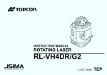
NON-MYDRIATIC RETINAL CAMERA
TRC-NW200
INTRODUCTION
Thank you for purchasing the TOPCON TRC-NW200 Non-Mydriatic Retinal
Camera.
This instrument is used to observe and photograph the posterior segment of the
eye.
This instrument has the following innovative features:
• High-quality digital imaging
• Easy operation
• All-in-one system
• Enhanced computerized features
This manual outlines the TRC-NW200 Non-Mydriatic Retinal Camera, including
operating procedures, troubleshooting, maintenance and cleaning.
Before using the instrument, carefully read the "DISPLAY FOR SAFE USE" and the
"SAFETY CAUTIONS" to familiarize yourself with the features of the TRC-NW200
Non-Mydriatic Retinal Camera and to ensure that you operate it efficiently and
safely.
Always keep this Instruction Manual at hand.
1
CAUTIONS FOR USE
Basic caution
When moving the chinrest up and down, be careful not to catch the patient's hand.
[The patient may be injured.]
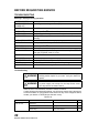
ENVIRONMENTAL CONDITIONS FOR USE
Temperature: 10°C ~ 40°C
Humidity: 30% ~ 75% (without dew condensation)
Air pressure: 700hPa ~ 1060hPa
STORAGE, USAGE PERIOD AND OTHERS
1. Environmental conditions
Temperature: 10°C ~ 40°C
Humidity: 30% ~ 75% (without dew condensation)
Air pressure: 700hPa ~ 1060hPa
2. When storing the instrument, ensure that the following conditions are met:
(1) The instrument must not be splashed with water.
(2) Store the instrument where air pressure, temperature, humidity, ventilation, sunlight,
dust, salty/sulfurous air, etc. do not give any negative side effect.
(3) Do not store or transport the instrument on a slope or uneven surface or in an area
where it is subject to vibrations or instability.
(4) Do not store the instrument where chemicals are stored or gas is generated.
ENVIRONMENTAL CONDITIONS FOR PACKAGING IN TRANSPORTATION
Temperature: -20°C ~ 50°C
Humidity: 10% ~ 95%
CHECKPOINTS FOR MAINTENANCE
1. Periodically inspect the instrument and its parts.
2. Before using the instrument again after a long period of inactivity, make sure that it operates safely and normally.
3. Be careful not to stain the objective lens with fingerprints, dirt, etc., as this will affect the
quality of pictures that the instrument takes.
4. When the instrument is not in use, cap the objective lens and apply the dust cover to the
instrument.
5. If the objective lens is stained, clean it according to "Cleaning the objective lens" in this
manual.
2
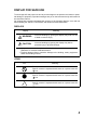
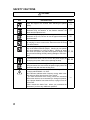
DISPLAY FOR SAFE USE
To encourage safe and proper use and to prevent danger to the operator and others or potential damage to properties, important messages are put on the instrument body and inserted in
the instruction manual.
We suggest that everyone understand the meaning of the following displays, icons and text
before reading the "SAFETY CAUTIONS" and observe all listed instructions.
DISPLAYS
Display
Meaning
WARNING
Incorrect handling by ignoring this display may lead to a risk
of death or serious injury.
CAUTION
Incorrect handling by ignoring this display may lead to
personal injury or physical damage.
• Injury refers to cuts, bruises, burns, electric shock, etc. which do not require hospitalization or extended medical treatment.
• Physical damage refers to extensive damage to the building, nearby equipment
and/or surrounding furniture.
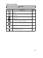
ICONS
Icon
Meaning
Prohibition.
Specific content is expressed with words or a picture near the
icon.
Mandatory Action
Specific content is expressed with words or a picture near the
icon.
Caution
Specific content is expressed with words or a picture near the
icon.
3
SAFETY CAUTIONS
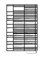
WARNINGS
Icon
4
Prevention item
Page
To avoid electric shock, be sure to unplug the power cable
before assembling. Also, do not plug the power cable in before
assembling.
17
To avoid fire and electric shock in case of leakage, be sure to
use a power supply equipped with a 3-plug AC receptacle for
proper grounding.
21
To avoid electric shock, do not attempt disassembling, rebuilding and/or repairs on your own. Ask your dealer for repairs.
88
Do not remove the covers from the main unit, chinrest unit or
power supply unit except for the lamp house cover. You may
receive an electric shock.
88
To avoid electric shock, be sure to remove the power cable
from the instrument body before removing the fuse cover.
Also, do not connect the power cable to the instrument body
with the fuse cover left unfixed.
96
To avoid fire and electric shock, install the instrument in a
place free of water and other liquids.
-----
To avoid fire and electric shock, do not put cups or vessels
containing liquids near the instrument.
-----
To avoid electric shock, do not insert metal objects into any
vents and/or slots.
-----
To avoid fire, use a properly rated fuse (T-5A,125V
100,110,120V, T-2.5A, 250V 220, 230, 240V) which matches
the display provided on the fuse holder.
96
To avoid fire in the event of an instrument malfunction, immediately turn OFF the Power switch and unplug the cable if you
see smoke coming from the instrument or if you detect a burning odor.
-----
SAFETY CAUTIONS
CAUTIONS
Icon
Prevention item
Page
To avoid pain and discomfort to the patient and/or damage to
the patient's eye, do not brighten the monitor lamp more than
necessary.
75
To avoid pain and discomfort to the patient and/or damage to
the patient's eye, do not brighten the photography light more
than necessary.
75
To prevent the instrument from falling and to avoid injury, do
not install the instrument on an uneven or unsteady surface,
including a slope.
17, 20
92
To avoid injury, do not place your fingers into the gap between
the instrument body and the power supply unit.
77
To avoid burns, do not touch the lamp immediately after it goes
off.
93
To avoid electric shock, do not handle the plugs with wet
fingers.
21
To avoid electric shock, do not touch the xenon lamp immediately after it flashes or burns out.
94
5
SAFETY CAUTIONS
CAUTIONS
Icon
6
Prevention item
Page
Adjust the height of the chinrest while watching the patient
directly.
71
To avoid injury to the patient's eyes and nose while moving the
instrument body, be attentive of the distance between the
patient and the objective lens.
77
To avoid falling and injury while moving the table with the
instrument on top of it, be sure to use an approved automatic
instrument table.
20
To prevent the instrument from falling and to avoid injury during carrying, be sure to secure the instrument with the fixing
knob at the bottom.
20
To avoid injury during carrying, be sure to hold the instrument
body at the bottom with two people. Carrying by one person
may cause backache or injury by falling. Holding at areas
other than the bottom may also cause pinched fingers and
injury, as well as falling, thereby causing damage to the instrument.
17, 20
To avoid electric shock, be sure to turn the power supply off
and unplug the power cable before replacing the lamp.
93, 94
To prevent the instrument body from falling and to avoid injury
during movement, be sure to affix the power supply unit to the
instrument body with the base locking knob.
-----
This instrument has been tested (with 120V/230V) and found
to comply with IEC60601-1-2: 2001.
This instrument radiates radio frequency energy within standard and may affect other devices in the vicinity.
If you have discovered that turning on/off the instrument
affects other devices, we recommend you change its position,
keep a proper distance from other devices, or plug it into a different outlet.
Please consult the dealer from whom you purchased the
instrument if you have any additional questions.
-----
USAGE AND MAINTENANCE
USAGE
Usage:
• The TRC-NW200 Non-Mydriatic Retinal Camera is an electric instrument for medical
use. Use this instrument under a doctor's guidance.
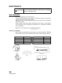
USER MAINTENANCE
To ensure the safety and performance of the instrument, all maintenance work,
unless specified in this manual, shall be conducted by trained service engineers.
The following maintenance tasks may be done by the user.
For details, see the relevant part of this manual.
Replacing lamps:
The illumination lamp and xenon lamp may be replaced by the user. For details,
see "Replacing the illumination lamp" on page 93 and "Replacing the xenon
lamp" on page 94.
Replacing fuses:
The fuses on the instrument body may be replaced by the user. For details, see
"Changing the fuse" on page 96.
Cleaning the objective lens:
The objective lens may be cleaned by the user. For details, see "Cleaning the
objective lens" on page 98.
ESCAPE CLAUSES
• TOPCON shall not take any responsibility for damage due to fire, earthquakes,
actions by third persons and other accidents, or damage due to negligence and
misuse by the user and any use under unusual conditions.
• TOPCON shall not take any responsibility for damage derived from inability to
properly use this instrument, such as loss of business profit and suspension of
business
• TOPCON shall not take any responsibility for damage caused from using this
instrument in a manner other than that described in this Instruction Manual.
• Diagnoses made shall be the responsibility of pertaining doctors and TOPCON
shall not take any responsibility for the results of such diagnoses.
7
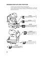
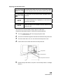
WARNING DISPLAYS AND POSITIONS
To ensure safety, the machine provides warning displays.
Use the instrument correctly by observing the display instructions. If any of the
following display labels are missing, contact your TOPCON dealer at the address
listed on the back cover.
CAUTION
y To avoid injury to the patient's face and hands,
be sure to adjust the height of the chinrest
while directly watching the patient.
CAUTION
y To avoid potential injury during operation,
do not touch the patient's eyes or nose with
the instrument.
WARNING
y Electrical shock can cause burns or a possible fire.
Turn the main power switch OFF and UNPLUG
the power cord before replacing the fuses.
Replace only with fuses of the correct rating.
CAUTION
y To avoid electric shock, be sure to turn
the power supply off and unplug the
power cable before replacing the lamp.
y To avoid burns, do not touch the lamp
immediately after it goes off.
WARNING
y To prevent electrical shock, do not remove
the cover.
There are no user serviceable parts inside,
refer servicing to qualified personnel.
WARNING
y Electrical shock can cause burns or a possible fire.
Turn the main power switch OFF and UNPLUG
the power cord before replacing the fuses.
Replace only with fuses of the correct rating.
8
CONTENTS
Introduction ....................................................................................................................1
Display for safe use .......................................................................................................3
Safety cautions ..............................................................................................................4
Usage and maintenance ................................................................................................7
Escape clauses..............................................................................................................7
Warning displays and positions......................................................................................8
COMPONENTS
Component names....................................................................................................... 11
Composition of parts which contact the human body................................................... 11
Control panel components ...........................................................................................12
Monitor screen .............................................................................................................13
Standard accessories...................................................................................................15
ASSEMBLY
Components.................................................................................................................16
ASSEMBLY PROCEDURE
Assembling the instrument body..................................................................................17
Confirmation after assembly ........................................................................................19
PREPARATIONS
Installing the instrument ...............................................................................................20
Connecting the power cable ........................................................................................21
Installation of the CompactFlash® card........................................................................22
Removal of the CompactFlash® card...........................................................................23
Connecting the external device....................................................................................24
Menu setting ................................................................................................................26
Setting the internal fixation target ................................................................................27
Setting the flash level...................................................................................................30
Setting the built-in CCD camera ..................................................................................31
Setting the ID number ..................................................................................................40
Setting of AE ................................................................................................................41
Reset from power save state .......................................................................................41
INITIAL SETTING
Preparation for initial setting ........................................................................................42
Setting the internal fixation target ................................................................................43
Switching of internal/external fixation target (option) ...................................................44
Setting the screen display............................................................................................47
System setting .............................................................................................................53
Setting the initial state..................................................................................................54
Setting the built-in CCD camera ..................................................................................58
Setting the ID number ..................................................................................................68
Setting the language ....................................................................................................70
BASIC OPERATIONS
Preparation for photography ........................................................................................71
Color photography (center) ..........................................................................................74
Photography of ear side / nose side ............................................................................82
9
Anterior segment photography.....................................................................................84
Playback and deletion of recorded image....................................................................85
PC mode ......................................................................................................................87
Finishing.......................................................................................................................87
BEFORE REQUESTING SERVICE
Troubleshooting ...........................................................................................................88
SPECIFICATIONS AND PERFORMANCE
Specifications ...............................................................................................................90
Electromagnetic compatibility ......................................................................................90
Electric rating ...............................................................................................................90
System classification....................................................................................................91
Dimensions and weight................................................................................................91
Purpose of use.............................................................................................................91
Operation principle.......................................................................................................91
MAINTENANCE
Daily checkups.............................................................................................................92
Cleaning.......................................................................................................................98
Disposing the product ..................................................................................................99
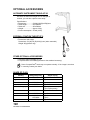
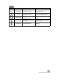
OPTIONAL ACCESSORIES
Automatic instrument table AIT-20 .............................................................................100
External fixation target EF-2 ......................................................................................100
Other optional accessories ........................................................................................100
Shape of plug.............................................................................................................100
Symbol .......................................................................................................................101
10
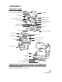
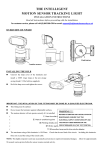
COMPONENTS
COMPONENT NAMES
Connector
Access lamp
Diopter compensation lens selector
Focusing knob
Color video monitor
Image quality adjustment knob
Photography switch
IR filter selector
Omni-directional joystick
Control panel
Base brake knob
Vertical position mark
Power lamp
Fuse holder
Fixing knob (for carrying)
Forehead rest
Objective lens
Canthus marker
Lamp house cover screw
Chinrest
Chinrest tissue pin
Lamp house cover
Base
Power switch
Fuse holder
Power supply unit
External connection terminal
COMPOSITION OF PARTS WHICH CONTACT THE HUMAN BODY
Forehead rest: Silicone rubber
Chinrest: Acrylonitrile butadiene styrene resin
11
COMPONENTS
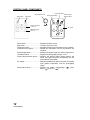
CONTROL PANEL COMPONENTS
Thumbnail switch
Mode selector knob
Menu switch
Split switch
Flash level switch
(-, reset, +)
Picture angle switch
Fixation target
selector switch
No. switch
Illumination level
switch (-, +)
Menu switch ................................... Displays the Menu screen.
Split switch ..................................... Turns the split lines on/off.
Flash level switch........................... Adjusts the flash level for the patient's eye condition.
Illumination level switch ................. Adjusts the illumination level for the patient's eye
condition.
Picture angle switch ....................... Switches the picture angle 45° and the digital zoom.
Thumbnail switch ........................... Displays the photography images in line.
Fixation target selector switch........ Switches the internal fixation target position, the
center (the aged insurance law position) and the
nose side/ear side position.
No. switch........................................ Selects and deletes the optional numeral / ID number
input (patient information) and the photography
image.
Mode selector knob........................ Changes the modes, "photography" (
), "playback" (
) and "PC" (
).
12
COMPONENTS
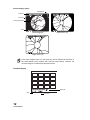
MONITOR SCREEN
Monitor screen
Patient ID
File name
Xenon charging display
Rest of frames
Right/left eye
( ) scale
Flash level compensation display
Alignment bright spots
Flash level display
Split lines
Picture angle display
Fixation target position display
Illumination level
TCN
Menu screen
MAIN MENU
Cursor
FIXATION TYPE
INTERNAL/EXTERNAL FIX
FIXATION PATTERNS
FLASH LEVEL
CAMERA
ID TYPE
AE
Input guide display
13
COMPONENTS
Preview display (color)
Right/left eye
Patient ID
File name
Photography image
Date
Picture angle 45°
Digital zoom (×2)
Digital zoom (×4)
In the case of digital zoom (×2), the mask may not be indicated at the center of
the review display on the monitor, and it may be partly missing. However, the
recorded image is not affected by this phenomenon.
Thumbnail display
Patient ID
Date
14
COMPONENTS
File name
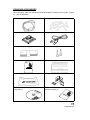
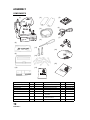
STANDARD ACCESSORIES
Upon unpacking, make sure that all the following standard accessories are included. Figures
in ( ) are the quantities
Power cable (1)
Fuse (9)
CompactFlash® card 32MB (1)
USB cable (1)
Chinrest tissue paper (1)
Chinrest tissue pin (2)
Instruction manual (1)
Spare parts case (1)
Dust cover (1)
Cord bracket (1)
TRC-NW200 Software Kit
Setup disk (1)
TRC-NW200 Software Kit
Instruction manual (1)
S
C areisk
TRSofetwtup D
0
20
Wt
-N Ki
IN
NO STRU
C
N
-M TION
T
YD
MA
NU
AL
So RC-N RIATIC
ftw W2
R
are 00 ETINAL
CA
Kit
M
ER
A
15
COMPONENTS
ASSEMBLY
COMPONENTS
(1)
(5)
(2)
(6)
(3)
(7)
(4)
(8)
(11)
(14)
S
C areisk
TRSofetwtup D
0
20
Wt
-N Ki
(9)
(12)
(15)
(10)
(13)
IN
NO STRU
C
N
-M TION
T
YD
MA
NU
AL
So RC-N RIATIC
ftw W2
R
are 00 ETINAL
CA
Kit
ME
R
Description
Quantity
Container
Description
Quantity
A
Container
(1) Instrument body
1
(9) Spare parts case
(2) Rail cover
2
(10) Chinrest tissue paper
1
Spare parts case
(3) Power cable
1
(11) Chinrest tissue pin (spare)
2
Spare parts case
(4) Phillips screwdriver
1
(12) Fuse (spare)
9
Spare parts case
(5) CompactFlash® card 32MB
1
Spare parts case (13) TRC-NW200 Instruction Manual
1
(6) USB cable
1
(14) TRC-NW200 Software Kit
Setup disk
1
(7) Cord bracket
1
(15) TRC-NW200 Software Kit
Instruction manual
1
(8) Dust cover
1
16
ASSEMBLY
1
ASSEMBLY PROCEDURE
ASSEMBLING THE INSTRUMENT BODY
1
2
WARNING
To avoid electric shock, be sure to unplug the power cable
before assembling. Also, do not plug the power cable in
before assembling.
CAUTION
To prevent the instrument from falling and to avoid injury,
do not install the instrument on an uneven or unsteady
surface, including a slope.
CAUTION
To avoid injury during carrying, be sure to hold the instrument body at the bottom with two people. Carrying by
one person may cause backache or injury by falling.
Holding at areas other than the bottom may also cause
pinched fingers and injury, as well as falling, thereby causing damage to the instrument.
NOTE
Since the upper part and lower part of the instrument
body are merely connected with the power cable, take
them out together so they do not separate from each
other.
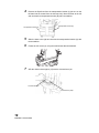
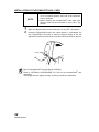
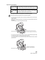
Take the instrument body (1) out of the container and put it on the table.
Slightly raise the omni-directional joystick, and pull out the cushion from
the lower part of the base in the arrow direction.
Omni-directional joystick
Styrofoam
Sponge
Cushion
Sponge
3
Wipe the sliding board with a cloth to remove any dirt.
17
ASSEMBLY PROCEDURE
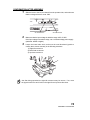
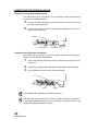
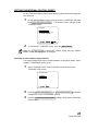
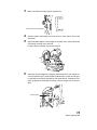
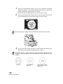
4
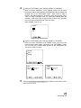
Remove the Styrofoam from the transportation bracket (A) (the one on the
left-hand side as viewed from the chinrest side). Move the base to the left
and unscrew the transportation bracket (B) with a screwdriver.
Transportation bracket (A)
5
Transportation bracket (B)
Slide the base to the right and unscrew the transportation bracket (A) with
the screwdriver.
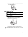
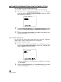
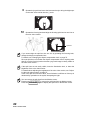
6
Fasten the rail covers (2), using the small screws that are attached.
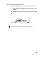
7
Affix the chinrest tissue paper (10) with the chinrest tissue pin.
Chinrest tissue pin
Chinrest tissue paper
18
ASSEMBLY PROCEDURE
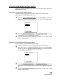
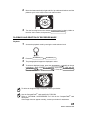
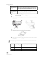
CONFIRMATION AFTER ASSEMBLY
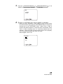
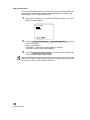
1
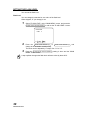
Slide the base to the left, as viewed from the operator side, and make sure
that the voltage selector is set at 100V.
100V
120V
220V
240V
VOLTAGE SELECTOR
Set at the left-end
2
3
Set at the left-end
Make sure that the input voltage is within the range ±10% of 100V.
If the input voltage exceeds the range, use a constant-voltage power supply
(marketed: 400VA or higher).
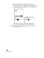
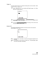
Loosen the base brake knob, and move the omni-directional joystick to
confirm that it moves smoothly in the following directions:
1) Right-left movement
2) Back-forth movement
3) Up-down movement
Just after being unpacked, the right-left movement may be uneven. If so, move
the joystick with force to its limits in the right-left and up-down directions.
19
ASSEMBLY PROCEDURE
PREPARATIONS
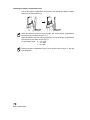
INSTALLING THE INSTRUMENT
1
2
CAUTION
To prevent the instrument from falling and to avoid injury
during carrying, be sure to secure the instrument with the
fixing knob at the bottom.
CAUTION
To avoid injury during carrying, be sure to hold the instrument body at the bottom with two people. Carrying by
one person may cause backache or injury by falling.
Holding at areas other than the bottom may also cause
pinched fingers and injury, as well as falling, thereby causing damage to the instrument.
CAUTION
To avoid falling and injury while moving the table with the
instrument on top of it, be sure to use an approved automatic instrument table.
CAUTION
To prevent the instrument from falling and to avoid injury,
do not install the instrument on an uneven or unsteady
surface, including a slope.
Fasten the fixing knob.
Firmly hold the instrument body at the specified positions, and put it on the
automatic instrument table.
For details about the automatic instrument table, see "OPTIONAL ACCESSORIES" on page 100.
TRC-NW200
Holding positions
Fixing knob
3
20
PREPARATIONS
Holding the instrument body
After installing the instrument, fully loosen the fixing knob.
The instrument body is freed to move.
4
If the instrument body is slightly off level, fine-adjust the height by properly
operating the four adjusters.
Do not extend the adjuster past 1cm.
Adjuster
CONNECTING THE POWER CABLE
1
2
3
WARNING
To avoid fire and electric shock in case of leakage, be sure
to use a power supply equipped with a 3-plug AC receptacle for proper grounding.
CAUTION
To avoid electric shock, do not handle the plugs with wet
fingers.
Make sure that the main switch of the instrument body is OFF.
Attach the power cable to the instrument body.
Plug the power cable into the 3-plug AC receptacle with grounding.
When the external fixation target (optional accessory) is used, set it on the connector of the chinrest.
21
PREPARATIONS
INSTALLATION OF THE COMPACTFLASH® CARD
NOTE
1
2
• Insert the CompactFlash® card in the correct direction.
If it is not inserted properly, the inside of the instrument
may be damaged.
• Before inserting the CompactFlash® card, make sure
that the switch on the instrument is in the "OFF" (O)
position.
Make sure that the switch on the instrument is in the "OFF" (O) position.
Insert the CompactFlash® card in the correct direction. As illustrated, set
the CompactFlash® card with its memory capacity display at the top
against the insertion port and insert it into the innermost section of the slot.
Use the CompactFlash® card specified by TOPCON.
Refer to "OPTIONAL ACCESSORIES" on P.100 for the CompactFlash® card
description.
If the image does not appear normally, contact your dealer for assistance.
22
PREPARATIONS
REMOVAL OF THE COMPACTFLASH® CARD
NOTE
1
2
Before removing the CompactFlash® card, make sure that
the switch on the instrument is in the "OFF" (O) position.
Make sure that the switch on the instrument is in the "OFF" (O) position.
Pull out the CompactFlash® card from the slot.
Right after the operation of the instrument, the CompactFlash® card may be hot.
Be careful when removing it.
If the CompactFlash® card is inserted or removed while the access lamp is blinking (reviewing is being done or "BUSY" is being displayed), the image data stored
on the CompactFlash® card may be destroyed.
23
PREPARATIONS
CONNECTING THE EXTERNAL DEVICE
Connection to computer/ten button keypad
This instrument may be connected to the computer/ten button keypad through
the external connection terminal.
1
2
Connect the USB cable (packed together) from the computer to the serial
terminal 1 of this instrument.
Connect the connector of the ten button keypad (optional) to the serial terminal 2 of this instrument.
Serial terminal 2
Serial terminal 1
Installation of the USB cable cord bracket
By installing this cord bracket, you can prevent the USB cable from being accidentally removed from the TRC-NW200.
1
2
3
Tighten the attached cord bracket onto the instrument by using the accessory screw.
Connect the connector of the USB cable to the opening of the cord bracket.
Fit the USB cable into the clamp of the cord bracket.
Clamp
Opening
Use the USB cable specified by TOPCON (accessory).
The USB cable may not connect to all PC's, so please ensure the connection is
correct before attempting to fit the plug. Contact your authorized dealer for any
assistance regarding the USB connection.
24
PREPARATIONS
Image output to an external monitor and others
Through the image output port on the external connection terminal, the image
displayed on the color video monitor can be displayed on an external monitor.
1
2
3
Connect the BNC cable (optional) to the image output terminal 1 of this
instrument.
Connect the other end of the BNC cable to the input terminal of an external
monitor.
The image output terminal 2 is used to output the data to a specialized
printer.
Image output terminal 1
Image output terminal 2
Contact your dealer for any questions regarding these connections.
25
PREPARATIONS
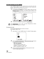
MENU SETTING
On the "MAIN MENU" display, setting of internal fixation target, switching of internal/external fixation target, flash level, setting of built-in CCD camera, setting of
ID number and setting of AE can be selected.
Preparation for menu setting
1
2
Check the power cable connection.
For details about the connection, see "CONNECTING THE POWER
CABLE" on page 21.
Turn the
ON (I).
POWER SWITCH
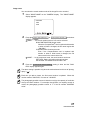
Displaying the menu screen
1
2
Check the monitor screen.
Press the MENU SWITCH on the control panel.
Check the "MAIN MENU" screen.
MAIN MENU
Cursor
3
Press the
moves.
FIXATION TYPE
INTERNAL/EXTERNAL FIX
FIXATION PATTERNS
FLASH LEVEL
CAMERA
ID TYPE
AE
FLASH LEVEL SWITCH (+)
Returning to the Monitor screen
1
26
PREPARATIONS
Press the
MENU SWITCH
.
or
FLASH LEVEL SWITCH (-)
; the cursor
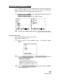
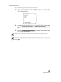
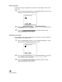
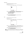
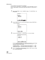
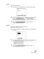
SETTING THE INTERNAL FIXATION TARGET
In setting of the internal fixation target, fixation target on/flicker status and fixation
target pattern can be set.
Switching of internal fixation target on/flicker
The internal fixation target can be switched between on and flicker states.
When shipped, "FLICKERING" (flicker) is set.
1
Move the cursor to "FIXATION TYPE" on the "MAIN MENU" screen, and
press the FLASH LEVEL SWITCH (RESET) to call out the "FIXATION TYPE"
screen.
FIXATION TYPE
CONSTANT
FLICKERING
2
3
Press the FLASH LEVEL SWITCH (+) or FLASH LEVEL SWITCH (-) and select
"CONSTANT" (on) or "FLICKERING" (flicker).
Press the FLASH LEVEL SWITCH (RESET) ; the setting is done and the "MAIN
MENU" screen returns.
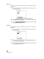
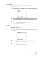
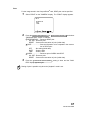
Switching of internal/external fixation target (option)
You can change the internal/external fixation target.
When shipped, "INTERNAL" (internal fixation target) is the default setting.
1
Move the cursor to "INTERNAL/EXTERNAL FIX" on the "MAIN MENU"
screen and press the FLASH LEVEL SWITCH (RESET) to access the "INTERNAL/EXTERNAL FIX" screen.
INTERNAL/EXTERNAL FIX
INTERNAL
EXTERNAL
2
3
Press the FLASH LEVEL SWITCH (+) or FLASH LEVEL SWITCH (-) and select
"INTERNAL" (internal fixation target) or "EXTERNAL" (external fixation target).
Press the FLASH LEVEL SWITCH (RESET) ; the setting is done and the "MAIN
MENU" screen is reset.
27
PREPARATIONS
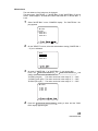
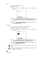
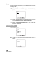
Internal fixation target pattern
You can select the internal fixation target pattern from two types, "ORIGINAL"
(default pattern ) and "CUSTOM" (pattern to be set optionally).
When shipped, "ORIGINAL" is set.
1
Move the cursor to "FIXATION PATTERNS" on the "FIXATION" screen and
press the FLASH LEVEL SWITCH (RESET) to access the "FIXATION PATTERNS" screen.
FIXATION PATTERNS
MODE
PATTERNS
• Select the "ORIGINAL" or "CUSTOM" mode in "MODE" and set the data
in "PATTERNS".
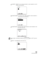
2
3
Press the FLASH LEVEL SWITCH (+) or
"MODE" or "PATTERNS".
ORIGINAL
CUSTOM
PREPARATIONS
and select
Press the FLASH LEVEL SWITCH (+) or FLASH LEVEL SWITCH (-)
"MODE" screen and select "ORIGINAL" or "CUSTOM".
MODE
28
FLASH LEVEL SWITCH (-)
on the
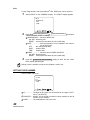
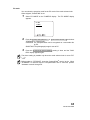
4
1
Setting of "PATTERNS" when changing "MODE" to "ORIGINAL"
When you select "ORIGINAL" on the "MODE" screen, you can select
the internal fixation target patterns (P2A/P2B/P3A/P3B) of "center/nose
side/ear side" on the "PATTERNS" screen. When "P2A" or "P2B" is
selected, the fixation targets for "center/nose side" are indicated. When
"P3A" or "P3B" is selected, those for "center/nose side/ear side" are
indicated. "P2B" and "P3B" are used to take a picture of the periphery
of the eye ground compared with "P2A" and "P3A".
When shipped, "P2A" is set.
PATTERNS
P2A
P2B
P3A
P3B
2
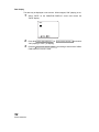
Setting of "PATTERNS" when changing "MODE" to "CUSTOM"
When you select "CUSTOM" on the "MODE" screen, you can set the
internal fixation target pattern optionally on the "PATTERNS" screen.
You can freely set a fixation target position for the photography with
optic disc or macula in focus.
PATTERNS
NASAL
TEMPORAL
5
NASAL
TEMPORAL
POSITION:0(OFF/-2~+2)
FLASH
:-4(-8~+8)
POSITION:0(OFF/-2~+2)
FLASH
:+4(-8~+8)
Press the FLASH LEVEL SWITCH (RESET) ; the setting is done and the "FIXATION" screen is reset.
29
PREPARATIONS
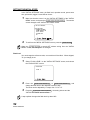
SETTING THE FLASH LEVEL
You can set the flash level.
Flash level
You can change the standard or zero value of the flash level.
When shipped, "0" (no change) is set.
1
Select "FLASH LEVEL" on the "MAIN MENU" screen, and press the
FLASH LEVEL SWITCH (RESET) to call out the "FLASH LEVEL" screen.
FLASH LEVEL
LEVEL
2
3
0
Press the FLASH LEVEL SWITCH (+) or FLASH LEVEL SWITCH (-)
change to the desirable correction step.
The value can be adjusted by 17 steps, from "+8" to "-8".
Press the FLASH LEVEL SWITCH (RESET) ; setting is done and the "MAIN
MENU" screen returns.
A step up/down changes the flash level reference value by about 20%.
30
PREPARATIONS
and
SETTING THE BUILT-IN CCD CAMERA
In the "CAMERA" display menu, the compression ratio, record pixels, gain, white
balance, image emphasis, contrast, color, CF format, PC mode, image name,
date/time, date form, file protect function and print can be set.
1
Move the cursor to "CAMERA" on the "MAIN MENU" display and press the
FLASH LEVEL SWITCH (RESET) .
The Monitor display changes to the "CAMERA" display.
CAMERA 1/2
CAMERA 2/2
QUALITY
SIZE
GAIN
WHITE BAL.
ENHANCE
CONTRAST
COLOR
CF FORMAT
PC MODE
2
IMAGE NAME
DATE
DATE FORM
FILE PROTECT
PRINT
To exit from the "CAMERA" display, press the
FLASH LEVEL SWITCH (RESET)
.
File compression ratio
Set the compression ratio of the file to be stored.
When shipped, "BASIC" is set.
1
Select "QUALITY" on the "CAMERA" display. The "QUALITY" display
appears.
QUALITY
BMP
TIFF
FINE
NORMAL
BASIC
2
3
Press the FLASH LEVEL SWITCH (+) or FLASH LEVEL SWITCH (-) and select
the desirable ratio from the following:
"BMP" (No compression)
"TIFF" (No compression)
"FINE" (Compression to approx. 1/4)
"NORMAL" (Compression to approx. 1/8)
"BASIC" (Compression to approx. 1/16)
Press the FLASH LEVEL SWITCH (RESET) ; setting is done and the "CAMERA"
display appears again.
31
PREPARATIONS
Record pixels
Set the size of the image to be recorded.
When shipped, "FULL" is set.
1
Select "SIZE" on the "CAMERA" display. The "SIZE" display appears.
SIZE
FULL
UXGA
XGA
2
3
Press the FLASH LEVEL SWITCH (+) or
the desirable size from the following:
"FULL" (2048 × 1536 pixels)
"UXGA" (1600 × 1200 pixels)
"XGA" (1024 × 768 pixels)
FLASH LEVEL SWITCH (-)
and select
Press the FLASH LEVEL SWITCH (RESET) ; setting is done and the "CAMERA"
display appears again.
Gain
The gain (luminance) of image can be changed.
When shipped, "0" is set.
1
Select "GAIN" on the "CAMERA" display. The "GAIN" display appears.
GAIN
LEVEL
2
3
0
Press the FLASH LEVEL SWITCH (+) or FLASH LEVEL SWITCH (-) and
change "GAIN" (luminance) to the desirable correction step. The value can
be adjusted by 25 steps, from "+12" to "-12".
Press the FLASH LEVEL SWITCH (RESET) ; setting is done and the
"CAMERA" display appears again.
As with most commercial cameras, gain is displayed in "dB". Increase/decrease
the value by 1 step (3 steps), and gain can be changed by approx. 12% (approx.
40%).
32
PREPARATIONS
White balance
The color balance of the image can be changed.
The three types, "WHITE BAL. 1", "WHITE BAL. 2" and "WHITE BAL. 3" can be
stored. When shipped, "R-GAIN 96/G-GAIN 70/B-GAIN 85" of "WHITE BAL. 1"
is set.
1
Select "WHITE BAL." on the "CAMERA" display. The "WHITE BAL." display appears.
WHITE BAL.
SELECT
WHITE BAL.1
WHITE BAL.2
WHITE BAL.3
2
On the "SELECT" screen, select the white balance setting ("WHITE BAL. 1
~ 3") to be validated.
SELECT
WHITE BAL.1
WHITE BAL.2
WHITE BAL.3
3
On each of "WHITE BAL. 1" to "WHITE BAL. 3", you can set data.
Press the FLASH LEVEL SWITCH (+) or FLASH LEVEL SWITCH (-) and
change each item to the desirable numeral:
"R-GAIN" (red gain) : The value can be set in the range of "1" ~ "255".
"G-GAIN" (green gain) : The value can be set in the range of "1" ~ "255".
"B-GAIN" (blue gain) : The value can be set in the range of "1" ~ "255".
WHITE BAL.1
R-GAIN
G-GAIN
B-GAIN
4
096
070
085
Press the FLASH LEVEL SWITCH (RESET) ; setting is done and the "CAMERA" display appears again.
33
PREPARATIONS
Image emphasis
Image emphasis allows you to change certain image characteristics.
When shipped, "0" is set.
1
Select "ENHANCE" on the "CAMERA" display. The "ENHANCE" display appears.
ENHANCE
LEVEL 0
2
3
Press the FLASH LEVEL SWITCH (+) or FLASH LEVEL SWITCH (-) and change
the level to the desirable one. You can adjust the level by 9 steps, from "-4"
to "+4".
Press the FLASH LEVEL SWITCH (RESET) ; setting is done and the "CAMERA"
display appears again.
Contrast
The image contrast can be changed.
When shipped, "0" is set.
1
Select "CONTRAST" on the "CAMERA" display. The "CONTRAST" display appears.
CONTRAST
LEVEL 0
2
3
34
PREPARATIONS
Press the FLASH LEVEL SWITCH (+) or FLASH LEVEL SWITCH (-) and adjust
the contrast. The contrast can be adjusted by 9 steps, from "-4" to "+4".
Press the FLASH LEVEL SWITCH (RESET) ; setting is done and the "CAMERA" display appears again.
Color
The image color depth can be changed.
When shipped, "0" is set.
1
Select "COLOR" on the "CAMERA" display.
appears.
The "COLOR" display
COLOR
LEVEL 0
2
3
Press the FLASH LEVEL SWITCH (+) or FLASH LEVEL SWITCH (-) and adjust
the image color depth. The color depth can be adjusted by 9 steps, from
"-4" to "+4".
Press the FLASH LEVEL SWITCH (RESET) ; setting is done and the "CAMERA" display appears again.
CF format
You may use this function to format a new CompactFlash® card.
When shipped, "CANCEL" (format is not done) is set.
1
Select "CF FORMAT" on the "CAMERA" display. The "CF FORMAT" display appears.
CF FORMAT
FORMAT
CANCEL
2
3
Press the FLASH LEVEL SWITCH (+) or FLASH LEVEL SWITCH (-) and select
"FORMAT" (format is done) or "CANCEL" (format is not done).
Press the FLASH LEVEL SWITCH (RESET) ; the setting is done and the "CAMERA" display appears again.
When format is selected, all the data including the file-protect-used files are
erased.
The above setting is possible only when the mode selector knob is set at "photography" (
) or "playback" (
).
35
PREPARATIONS
PC mode
You can select the operation mode for the PC mode of the mode selector knob.
When shipped, "SHOOTING" is set.
1
Select "PC MODE" on the "CAMERA" display. The "PC MODE" display
appears.
PC MODE
STORAGE
SHOOTING
2
3
Press the FLASH LEVEL SWITCH (+) or FLASH LEVEL SWITCH (-) and select
"STORAGE" or "SHOOTING".
STORAGE ....... The CompactFlash® card is recognized as a removable
disc by PC.
SHOOTING ..... The photography image is sent to PC.
Press the FLASH LEVEL SWITCH (RESET) ; setting is done and the "CAMERA" display appears again.
The above setting is possible only when the mode selector knob is set at "PC"
(
).
Before setting to "STORAGE", insert the CompactFlash® card to its slot. When
"STORAGE" is canceled and the CompactFlash® card is removed, perform
"hardware removal" through PC.
36
PREPARATIONS
Image name
You can select the record number mode of the image file to be recorded.
1
Select "IMAGE NAME" on the "CAMERA" display. The "IMAGE NAME"
display appears.
IMAGE NAME
MODE
NAME
2
3
Press the FLASH LEVEL SWITCH (+) or FLASH LEVEL SWITCH (-) and select
"MODE" or "NAME".
1 MODE.......The record number mode of a file can be selected.
NON-CONTINUATION: Normal mode
When the CompactFlash® card is replaced with another
or when a folder is changed, the file name begins with
"100-0001".
CONTINUATION: Continuous mode
Even if the CompactFlash® card is replaced with
another or when a folder name is changed, the file
name stored in the camera is the first.
2 NAME .......In the continuous mode, the record number can be set.
SET DATA: Setting is possible with optional data.
AUTO NUM: The usable lowest number is set.
Press the FLASH LEVEL SWITCH (RESET) ; setting is done and the "CAMERA" display appears again.
The above setting is possible only when the mode selector knob is set at "photography" (
).
Each time you take a picture, the final record number is updated. When this
number reaches "999-1000", it is reset to "100-0000".
The photography possible counter is limited not only by the capacity of media but
also by the blank numbers. For example, though there is a capacity enough in
media, the photography possible counter is "1" if the file number "999-0999"
exists.
37
PREPARATIONS
Date/time
You can set the date and time.
1
Select "DATE" on the "CAMERA" display. The "DATE" display appears.
DATE
04-04-20
17:36
2
3
Press the FLASH LEVEL SWITCH (+) or FLASH LEVEL SWITCH (-) and move
the cursor to the item to be set.
Press the FLASH LEVEL SWITCH (+) or FLASH LEVEL SWITCH (-) and
change the numerals to the desired ones.
Press the FLASH LEVEL SWITCH (RESET) ; setting is done and the
"CAMERA" display appears again.
Date form
You can set the display order of year, month and day.
When shipped, "year-month-day" is set.
1
Select "DATE FORM" on the "CAMERA" display. The "DATE FORM" display appears.
DATE FORM
YY-MM-DD
MM-DD-YY
DD-MM-YY
2
3
38
PREPARATIONS
Press the FLASH LEVEL SWITCH (+) or
the desirable order from the following:
"YY-MM-DD" (year-month-day)
"MM-DD-YY" (month-day-year)
"DD-MM-YY" (day-month-year)
FLASH LEVEL SWITCH (-)
and select
Press the FLASH LEVEL SWITCH (RESET) ; setting is done and the
"CAMERA" display appears again.
File protect function
You can set the file protection setting for the camera.
1
Select "FILE PROTECT" on the "CAMERA" display.
TECT" display appears.
The "FILE PRO-
FILE PROTECT
ALL SET
RESET
EXIT
2
3
Press the FLASH LEVEL SWITCH (+) or FLASH LEVEL SWITCH (-) and select
"ALL SET" (exclusively for reading) or "RESET" (not exclusively for reading).
Press the FLASH LEVEL SWITCH (RESET) ; the setting is done and the "CAMERA" display appears again.
When format is selected, all the data are erased even if file protect is used.
The above setting is possible only when the mode selector knob is set at "playback" (
).
39
PREPARATIONS
Print
For the image stored in the CompactFlash® card, DPOF print can be reserved.
1
Select "PRINT" on the "CAMERA" display. The "PRINT" display appears.
PRINT
RESERVATION
DATE
INDEX
2
3
Press the FLASH LEVEL SWITCH (+) or FLASH LEVEL SWITCH (-) and select
"RESERVATION", "DATE" or "INDEX".
1 RESERVATION ... : Reserves DPOF print.
ALL SET : Reserves print.
RESET : Cancels the reservation of print. (Initial data)
2 DATE ................... : Sets the information to be outputted in the reservation of DPOF print.
OFF
: No setting (Initial data)
DATE
: Sets the date.
TIME
: Sets the time.
3 INDEX ................. : Reserves print of INDEX with DPOF.
ALL SET : Reserves print.
RESET : Cancels the reservation of print. (Initial data)
Press the FLASH LEVEL SWITCH (RESET) ; setting is done and the "CAMERA" display appears again.
Setting of print is possible only when the "playback" mode is set.
SETTING THE ID NUMBER
The ID number can be set.
ID TYPE
ID
COUNTER
CODE
1
2
3
ID ................... The digits of ID number can be selected in the range of "OFF"
and 3 ~ 24 (DIGITS).
COUNTER..... ON/OFF for the 4-digit calculation counter attached to the ID
number can be selected.
CODE ............ The establishment code can be set.
40
PREPARATIONS
SETTING OF AE
The automatic photography brightness correction function can be selected.
AE
ON
OFF
1
2
ON ........The flash level is corrected to control the photography brightness
automatically.
OFF ......Photography is done with the set flash level. The photography brightness is not controlled automatically.
RESET FROM POWER SAVE STATE
This machine adopts the power save method for power saving.
When the instrument body is not operated within a set time, the power save function stops power supply to the monitor, illumination light source and photography
light source.
When power save sets in, the power lamp on the control panel flickers and the
monitor screen goes off.
1
Press the PHOTOGRAPHY SWITCH .
In a few seconds, the color video monitor is displayed and ready for photographing.
When shipped, the power save set time is 10 minutes.
To change the set time, contact your dealer or TOPCON (see the back cover).
41
PREPARATIONS
INITIAL SETTING
In the "INITIAL MENU" display, the record/playback, internal fixation target,
image display, system settings, initial settings, built-in CCD camera settings and
display language can be set.
PREPARATION FOR INITIAL SETTING
1
2
Make sure that the power cable is connected.
While pressing the
on the control panel and the
, turn the POWER SWITCH ON.
Hold the MENU SWITCH and the PHOTOGRAPHY SWITCH until the buzzer
sounds.
The Title screen is displayed, and in a few seconds the Monitor screen is
displayed.
MENU SWITCH
PHOTOGRAPHY SWITCH
3
Press the MENU SWITCH on the control panel; the "INITIAL MENU" screen
is displayed.
INITIAL MENU
FIXATION
MONITOR DISPLAY
SYSTEM SETTINGS
INITIAL SETTINGS
CAMERA
ID TYPE
LANGUAGE
4
To exit the "INITIAL MENU" screen, press the
MENU SWITCH
.
When the POWER SWITCH is turned OFF without exiting from the "INITIAL
MENU" screen, the settings are not changed.
Operate the switches by referring to “COMPONENT NAMES” on P. 11 and
“CONTROL PANEL COMPONENTS” on P. 12.
42
INITIAL SETTING
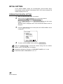
SETTING THE INTERNAL FIXATION TARGET
On the "FIXATION" display, fixation target on/flicker status and fixation target pattern can be set.
1
On the "INITIAL MENU" screen, move the cursor to "FIXATION," and press
the FLASH LEVEL SWITCH (RESET) . The Monitor screen changes to the
"FIXATION" screen.
FIXATION
FIXATION TYPE
INTERNAL/EXTERNAL FIX
FIXATION PATTERNS
2
To exit from the " FIXATION" screen, press the
MENU SWITCH
.
When the POWER SWITCH is turned OFF without exiting from the "INITIAL
MENU" screen, the settings are not changed.
Switching of internal fixation target on/flicker
The internal fixation target can be switched between on and flicker states. When
shipped, "FLICKERING" (flicker) is set.
1
Select "FIXATION TYPE" on the "FIXATION" screen and select the
"FIXATION TYPE" screen.
FIXATION TYPE
CONSTANT
FLICKERING
2
3
Press the FLASH LEVEL SWITCH (+) or FLASH LEVEL SWITCH (-) and select
"CONSTANT" (on) or "FLICKERING" (flicker).
Press the FLASH LEVEL SWITCH (RESET) ; setting is done and the "FIXATION"
screen returns.
43
INITIAL SETTING
SWITCHING OF INTERNAL/EXTERNAL FIXATION TARGET (OPTION)
You can change the internal/external fixation target.
When shipped, "INTERNAL" (internal fixation target) is the default setting.
1
Move the cursor to "INTERNAL/EXTERNAL FIX" on the "FIXATION"
screen and press the FLASH LEVEL SWITCH (RESET) to access the "INTERNAL/EXTERNAL FIX" screen.
INTERNAL/EXTERNAL FIX
INTERNAL
EXTERNAL
2
3
Press the FLASH LEVEL SWITCH (+) or FLASH LEVEL SWITCH (-) and select
"INTERNAL" (internal fixation target) or "EXTERNAL" (external fixation target).
Press the FLASH LEVEL SWITCH (RESET) ; the setting is done and the "FIXATION" screen is reset.
Internal fixation target pattern
You can select the internal fixation target pattern from two types, "ORIGINAL"
(default pattern ) and "CUSTOM" (pattern to be set optionally).
When shipped, "ORIGINAL" is set.
1
Move the cursor to "FIXATION PATTERNS" on the "FIXATION" screen and
press the FLASH LEVEL SWITCH (RESET) to access the "FIXATION PATTERNS" screen.
FIXATION PATTERNS
MODE
PATTERNS
• Select the "ORIGINAL" or "CUSTOM" mode in "MODE" and set the data
in "PATTERNS".
2
44
INITIAL SETTING
Press the FLASH LEVEL SWITCH (+) or
"MODE" or "PATTERNS".
FLASH LEVEL SWITCH (-)
and select
3
Press the FLASH LEVEL SWITCH (+) or FLASH LEVEL SWITCH (-)
"MODE" screen and select "ORIGINAL" or "CUSTOM".
on the
MODE
ORIGINAL
CUSTOM
4
1
Setting of "PATTERNS" when changing "MODE" to "ORIGINAL"
When you select "ORIGINAL" on the "MODE" screen, you can select
the internal fixation target patterns (P2A/P2B/P3A/P3B) of "center/nose
side/ear side" on the "PATTERNS" screen. When "P2A" or "P2B" is
selected, the fixation targets for "center/nose side" are indicated. When
"P3A" or "P3B" is selected, those for "center/nose side/ear side" are
indicated. "P2B" and "P3B" are used to take a picture of the periphery
of the eye ground compared with "P2A" and "P3A".
When shipped, "P2A" is set.
PATTERNS
P2A
P2B
P3A
P3B
45
INITIAL SETTING
2
Setting of "PATTERNS" when changing "MODE" to "CUSTOM"
When you select "CUSTOM" on the "MODE" screen, you can set the
internal fixation target pattern optionally on the "PATTERNS" screen.
You can freely set a fixation target position for the photography with
optic disc or macula in focus.
PATTERNS
NASAL
TEMPORAL
5
46
INITIAL SETTING
NASAL
TEMPORAL
POSITION:0(OFF/-2~+2)
FLASH
:-4(-8~+8)
POSITION:0(OFF/-2~+2)
FLASH
:+4(-8~+8)
Press the FLASH LEVEL SWITCH (RESET) ; the setting is done and the "FIXATION" screen is reset.
SETTING THE SCREEN DISPLAY
In the "MONITOR DISPLAY" menu, the flash level compensation display, flash
level display, illumination level display, picture angle display, fixation target position and date display can be set.
1
Make sure that the cursor is on the "MONITOR DISPLAY" of the "INITIAL
MENU" screen, and press the FLASH LEVEL SWITCH (RESET) . The Monitor
screen changes to the "MONITOR DISPLAY" screen.
MONITOR DISPLAY 1/2
FLASH LEVEL IN 9STEPS
FLASH LEVELS IN WS
ILLUMINATION LEVELS
ANGLE INDICATION
PERIPHERAL PATTERN
IMAGE NAME
ID NUMBER
RL
CF COUNTER
2
MONITOR DISPLAY 2/2
DATE
To exit from the "MONITOR DISPLAY" screen, press the
MENU SWITCH
.
When the POWER SWITCH is turned OFF without exiting from the "MONITOR
DISPLAY" screen, the settings are not changed.
Flash level compensation display
The flash level value may be displayed on the monitor for operator information.
When shipped, "ON" (display) is set.
1
On the “MONITOR DISPLAY”, select “FLASH LEVEL IN 9 STEPS”.
The “FLASH LEVEL IN 9 STEPS” display appears.
FLASH LEVEL IN 9STEPS
ON
OFF
2
3
Press the FLASH LEVEL SWITCH (+) or
"ON" (display) or "OFF" (no display).
FLASH LEVEL SWITCH (-)
and select
Press the FLASH LEVEL SWITCH (RESET) ; the setting is done and the
"MONITOR DISPLAY" screen returns.
47
INITIAL SETTING
Flash level display
The flash level may be displayed on the monitor. When shipped, "OFF" (no display) is set.
1
Select "FLASH LEVELS IN WS" on the "MONITOR DISPLAY" screen, and
choose the "FLASH LEVELS IN WS" screen.
FLASH LEVELS IN WS
ON
OFF
2
3
Press the FLASH LEVEL SWITCH (+) or
"ON" (display) or "OFF" (no display).
FLASH LEVEL SWITCH (-)
and select
Press the FLASH LEVEL SWITCH (RESET) ; the setting is done and the
"MONITOR DISPLAY" screen returns.
Illumination level display
The illumination level may be displayed on the monitor for operator assistance.
When shipped, "ON" (display) is set.
1
Select "ILLUMINATION LEVELS" on the "MONITOR DISPLAY" screen,
and select the "ILLUMINATION LEVELS" screen.
ILLUMINATION LEVELS
ON
OFF
2
3
48
INITIAL SETTING
Press the FLASH LEVEL SWITCH (+) or
"ON" (display) or "OFF" (no display).
FLASH LEVEL SWITCH (-)
and select
Press the FLASH LEVEL SWITCH (RESET) ; the setting is done and the
"MONITOR DISPLAY" screen returns.
Picture angle display
The picture angle may be displayed on the monitor. When shipped, "ON" (display) is set.
1
Select "ANGLE INDICATION" on the "MONITOR DISPLAY" screen, and
select the "ANGLE INDICATION" screen.
ANGLE INDICATION
ON
OFF
2
3
Press the FLASH LEVEL SWITCH (+) or
"ON" (display) or "OFF" (no display).
FLASH LEVEL SWITCH (-)
and select
Press the FLASH LEVEL SWITCH (RESET) ; the setting is done and the
"MONITOR DISPLAY" screen returns.
Internal fixation target position display
You can set the internal fixation target display. When shipped, "ON" (display) is
set.
1
Select "PERIPHERAL PATTERN" on the "MONITOR DISPLAY" screen,
and call out the "PERIPHERAL PATTERN" screen.
PERIPHERAL PATTERN
ON
OFF
2
3
Press the FLASH LEVEL SWITCH (+) or
"ON" (display) or "OFF" (no display).
FLASH LEVEL SWITCH (-)
and select
Press the FLASH LEVEL SWITCH (RESET) ; the setting is done and the
"MONITOR DISPLAY" screen returns.
49
INITIAL SETTING
Image name
The DCF file name may be displayed on the monitor. When shipped, "OFF" (no
display) is set.
1
Select "IMAGE NAME" on the "MONITOR DISPLAY" screen and access
the "IMAGE NAME" screen.
IMAGE NAME
ON
OFF
2
3
Press the FLASH LEVEL SWITCH (+) or
"ON" (display) or "OFF" (no display).
FLASH LEVEL SWITCH (-)
and select
Press the FLASH LEVEL SWITCH (RESET) ; the setting is done and the "MONITOR DISPLAY" screen is reset.
ID number
The patient ID number may be displayed on the monitor. When shipped, "ON"
(display) is set.
1
Select "ID NUMBER" on the "MONITOR DISPLAY" screen and access the
"ID NUMBER" screen.
ID NUMBER
ON
OFF
2
3
50
INITIAL SETTING
Press the FLASH LEVEL SWITCH (+) or
"ON" (display) or "OFF" (no display).
FLASH LEVEL SWITCH (-)
and select
Press the FLASH LEVEL SWITCH (RESET) ; the setting is done and the "MONITOR DISPLAY" screen is reset.
RL
The right/left eye information may be displayed on the monitor. When shipped,
"ON" (display) is set.
1
Select "RL" on the "MONITOR DISPLAY" screen and access the "RL" display.
RL
ON
OFF
2
3
Press the FLASH LEVEL SWITCH (+) or
"ON" (display) or "OFF" (no display).
FLASH LEVEL SWITCH (-)
and select
Press the FLASH LEVEL SWITCH (RESET) ; the setting is done and the "MONITOR DISPLAY" screen is reset.
CF counter
The remaining CF card number may be displayed on the monitor. When shipped,
"ON" (display) is set.
1
Select "CF COUNTER" on the "MONITOR DISPLAY" screen and access
the "CF COUNTER" display.
CF COUNTER
ON
OFF
2
3
Press the FLASH LEVEL SWITCH (+) or
"ON" (display) or "OFF" (no display).
FLASH LEVEL SWITCH (-)
and select
Press the FLASH LEVEL SWITCH (RESET) ; the setting is done and the "MONITOR DISPLAY" screen is reset.
51
INITIAL SETTING
Date display
The date may be displayed on the monitor. When shipped, "ON" (display) is set.
1
Select "DATE" on the "MONITOR DISPLAY" screen and access the
"DATE" display.
DATE
ON
OFF
2
3
52
INITIAL SETTING
Press the FLASH LEVEL SWITCH (+) or
"ON" (display) or "OFF" (no display).
FLASH LEVEL SWITCH (-)
and select
Press the FLASH LEVEL SWITCH (RESET) ; the setting is done and the "MONITOR DISPLAY" screen is reset.
SYSTEM SETTING
In the "SYSTEM SETTINGS" display, the recording method can be set.
When shipped, “TYPE1 MODE” (When taking a picture, recording is done and
reviewing is released.) is set.
1
Make sure that the cursor is on the "SYSTEM SETTINGS" of the "INITIAL
MENU" screen, and press the FLASH LEVEL SWITCH (RESET) . The monitor
screen changes to the "SYSTEM SETTINGS" screen.
SYSTEM SETTINGS
TYPE1 MODE
TYPE2 MODE
TYPE3 MODE
2
3
Press the FLASH LEVEL SWITCH (+) or FLASH LEVEL SWITCH (-) and select:
"TYPE1 MODE" (When taking a picture, recording is done and reviewing is released.)
"TYPE2 MODE" (When taking a picture, image stays on monitor.
When reviewing is released, recording is done.)
"TYPE 3 MODE" (When taking a picture, reviewing is automatically
released.)
Press the FLASH LEVEL SWITCH (RESET) ; the setting is done and the "INITIAL MENU" screen is called back.
When the POWER SWITCH is turned OFF without exiting from the "INITIAL
MENU" screen, the settings are not changed.
If the quality of the captured image is not good, press the
The captured image can be deleted.
No. SWITCH (-/DEL)
.
53
INITIAL SETTING
SETTING THE INITIAL STATE
In the "INITIAL SETTINGS" menu, the flash level, operation sound, power saver
time, split switch, trigger out and AE can be set.
1
Make sure that the cursor is on the "INITIAL SETTINGS" of the "INITIAL
MENU" screen, and press the FLASH LEVEL SWITCH (RESET) . The monitor
screen changes to the "INITIAL SETTINGS" screen.
INITIAL SETTINGS
FLASH LEVEL
OPERATION SOUND
POWER SAVER TIME
SPLIT SWITCH
TRIGGER OUT
AE
2
To exit from the "INITIAL SETTINGS" screen, press the
MENU SWITCH
.
When the POWER SWITCH is turned OFF without exiting from the "INITIAL
MENU" screen, the settings are not changed.
Flash level
You can change the reference value, or normal level of the flash . When shipped,
"0" (no change) is set.
1
Select "FLASH LEVEL" on the "INITIAL SETTINGS" screen, and choose
the "FLASH LEVEL" screen.
FLASH LEVEL
LEVEL
2
3
0
Press the FLASH LEVEL SWITCH (+) or FLASH LEVEL SWITCH (-)
change the flash level to the desirable correction step.
The value can be adjusted by 17 steps, from "+8" to "-8".
Press the FLASH LEVEL SWITCH (RESET) ; the setting is done and the
"INITIAL SETTINGS" screen returns.
A step up/down changes the flash level by about 20%.
54
INITIAL SETTING
and
Operation sound
The operation sound may be turned on or off. When shipped, "ON" (operation
sound) is set.
1
Select "OPERATION SOUND" on the "INITIAL SETTINGS" screen, and
call out the "OPERATION SOUND" screen.
OPERATION SOUND
ON
OFF
2
3
Press the FLASH LEVEL SWITCH (+) or FLASH LEVEL SWITCH (-) and select
"ON" (operation sound) or "OFF" (no operation sound).
Press the FLASH LEVEL SWITCH (RESET) ; the setting is done and the
"INITIAL SETTINGS" screen returns.
Power saver time
The power saver time can be set. When shipped, "10 MINUTES" (10 minutes) is set.
1
Select "POWER SAVER TIME" on the "INITIAL SETTINGS" screen, and
call out the "POWER SAVER TIME" screen.
POWER SAVER TIME
10 MINUTES
2
3
Press the FLASH LEVEL SWITCH (+) or FLASH LEVEL SWITCH (-) and select
a value in the range from "5 MINUTES" up to "60 MINUTES" in 5-minute
steps.
Press the FLASH LEVEL SWITCH (RESET) ; the setting is done and the
"INITIAL SETTINGS" screen returns.
55
INITIAL SETTING
Split switch function
You can select whether the split lines are ON or OFF, whether the internal fixation target is ON or OFF and whether the white balance setting pattern is changed or not.
When shipped, "SPLIT" (split ON/OFF) is set.
1
Select "SPLIT SWITCH" on the "INITIAL SETTINGS" display. The "SPLIT
SWITCH" display appears.
SPLIT SWITCH
SPLIT
WHITE BAL.
FIXATION
2
3
Press the FLASH LEVEL SWITCH (+) or FLASH LEVEL SWITCH (-) and select
one of the following:
"SPLIT" (split ON/OFF)
"WHITE BAL." (white balance setting pattern is changed)
"FIXATION" (internal fixation target ON/OFF)
Press the FLASH LEVEL SWITCH (RESET) ; the setting is done and the "INITIAL SETTINGS" display appears again.
When "FIXATION" is selected and the internal fixation target is turned off by the
split switch, the fixation target position display on the monitor display (at the lower
left on the color video monitor screen) is turned off.
56
INITIAL SETTING
Trigger out
The trigger signal output for an external recording device can be selected. When
shipped, "OFF" (no output) is set.
1
Select "TRIGGER OUT" on the "INITIAL SETTINGS" display. The "TRIGGER OUT" display appears.
TRIGGER OUT
ON
OFF
2
3
Press the FLASH LEVEL SWITCH (+) or
"ON" (output) or "OFF" (no output).
FLASH LEVEL SWITCH (-)
and select
Press the FLASH LEVEL SWITCH (RESET) ; the setting is done and the "INITIAL SETTINGS" screen is reset.
Setting of AE
The automatic photography brightness correction function can be selected.
When shipped, “OFF” is set.
AE
ON
OFF
1
2
ON:
The flash level is corrected to control the photography brightness automatically.
OFF: Photography is done with the set flash level. The photography brightness is not controlled automatically.
57
INITIAL SETTING
SETTING THE BUILT-IN CCD CAMERA
In the "CAMERA" display menu, the compression ratio, record pixels, gain, white
balance, image emphasis, contrast, color, CF format, PC mode, image name,
date/time, date form, file protect and print can be set.
1
Move the cursor to "CAMERA" on the "INITIAL MENU" display and press
the FLASH LEVEL SWITCH (RESET) . The Monitor display changes to the
"CAMERA" display.
For “CAMERA”, two displays are automatically switched by moving the cursor.
CAMERA 1/2
QUALITY
SIZE
GAIN
WHITE BAL.
ENHANCE
CONTRAST
COLOR
CF FORMAT
PC MODE
2
CAMERA 2/2
IMAGE NAME
DATE
DATE FORM
FILE PROTECT
PRINT
BACKUP
To exit from the "CAMERA" display, press the
MENU SWITCH
.
If the POWER SWITCH is set to "OFF" (O) without exiting from the "INITIAL
MENU" display, the settings are not changed.
File compression ratio
You can set the compression ratio of the file to be stored.
When shipped, "BASIC" is set.
1
Select "QUALITY" on the "CAMERA" display. The "QUALITY" display appears.
QUALITY
BMP
TIFF
FINE
NORMAL
BASIC
2
3
58
INITIAL SETTING
Press the FLASH LEVEL SWITCH (+) or FLASH LEVEL SWITCH (-) and select
the desirable ratio from the following:
"BMP" (No compression)
"TIFF" (No compression)
"FINE" (Compression to approx. 1/4)
"NORMAL" (Compression to approx. 1/8)
"BASIC" (Compression to approx. 1/16)
Press the FLASH LEVEL SWITCH (RESET) ; the setting is done and the
"CAMERA" display appears again.
Record pixels
You can set the size of the image to be recorded.
When shipped, "FULL" is set.
1
Select "SIZE" on the "CAMERA" display. The "SIZE" display appears.
SIZE
FULL
UXGA
XGA
2
3
Press the FLASH LEVEL SWITCH (+) or
the desirable size from the following:
"FULL" (2048 × 1536 pixels)
"UXGA" (1600 × 1200 pixels)
"XGA" (1024 × 768 pixels)
FLASH LEVEL SWITCH (-)
and select
Press the FLASH LEVEL SWITCH (RESET) ; setting is done and the
"CAMERA" display appears again.
Gain
The gain (luminance) of image can be changed.
When shipped, "0" is set.
1
Select "GAIN" on the "CAMERA" display. The "GAIN" display appears.
GAIN
LEVEL
2
3
0
Press the FLASH LEVEL SWITCH (+) or FLASH LEVEL SWITCH (-) and
change "GAIN" (luminance) to the desirable correction step. The value can
be adjusted by 25 steps, from "+12" to "-12".
Press the FLASH LEVEL SWITCH (RESET) ; setting is done and the
"CAMERA" display appears again.
As with most commercial cameras, gain is displayed in "dB". Increase/decrease
the value by 1 step (3 steps), and gain can be changed by approx. 12% (approx.
40%).
59
INITIAL SETTING
White balance
The color balance of the image can be changed.
The three types, "WHITE BAL. 1", "WHITE BAL. 2" and "WHITE BAL. 3" can be
stored. When shipped, "R-GAIN 96/G-GAIN 70/B-GAIN 85" of "WHITE BAL. 1"
is set.
1
Select "WHITE BAL." on the "CAMERA" display. The "WHITE BAL." display appears.
WHITE BAL.
SELECT
WHITE BAL.1
WHITE BAL.2
WHITE BAL.3
2
On the "SELECT" screen, select the white balance setting ("WHITE BAL. 1
~ 3") to be validated.
SELECT
WHITE BAL.1
WHITE BAL.2
WHITE BAL.3
3
On each of "WHITE BAL. 1" to "WHITE BAL. 3", you can set data.
WHITE BAL.1
R-GAIN
G-GAIN
B-GAIN
096
070
085
Press the FLASH LEVEL SWITCH (+) or FLASH LEVEL SWITCH (-) and change
each item to the desirable numeral:
"R-GAIN" (red gain) : The value can be set in the range of "1" ~ "255".
"G-GAIN" (green gain) : The value can be set in the range of "1" ~ "255".
"B-GAIN" (blue gain) : The value can be set in the range of "1" ~ "255".
4
60
INITIAL SETTING
Press the FLASH LEVEL SWITCH (RESET) ; setting is done and the "CAMERA" display appears again.
Image emphasis
Image emphasis allows you to change certain image characteristics.
When shipped, "0" is set.
1
Select "ENHANCE" on the "CAMERA" display. The "ENHANCE" display appears.
ENHANCE
LEVEL 0
2
3
Press the FLASH LEVEL SWITCH (+) or FLASH LEVEL SWITCH (-) and change
the level to the desirable one. You can adjust the level by 9 steps, from "-4"
to "+4".
Press the FLASH LEVEL SWITCH (RESET) ; setting is done and the
"CAMERA" display appears again.
Contrast
The image contrast can be changed.
When shipped, "0" is set.
1
Select "CONTRAST" on the "CAMERA" display. The "CONTRAST" display
appears.
CONTRAST
LEVEL 0
2
3
Press the FLASH LEVEL SWITCH (+) or FLASH LEVEL SWITCH (-) and adjust
the contrast. The contrast can be adjusted by 9 steps, from "-4" to "+4".
Press the FLASH LEVEL SWITCH (RESET) ; setting is done and the "CAMERA" display appears again.
61
INITIAL SETTING
Color
The image color depth can be changed.
When shipped, "0" is set.
1
Select "COLOR" on the "CAMERA" display.
appears.
The "COLOR" display
COLOR
LEVEL 0
2
3
Press the FLASH LEVEL SWITCH (+) or FLASH LEVEL SWITCH (-) and adjust
the image color depth. The color depth can be adjusted by 9 steps, from "-4"
to "+4".
Press the FLASH LEVEL SWITCH (RESET) ; setting is done and the "CAMERA" display appears again.
CF format
You may use this function to format a new CompactFlash® card.
When shipped, "CANCEL" (format is not done) is set.
1
Select "CF FORMAT" on the "CAMERA" display. The "CF FORMAT" display appears.
CF FORMAT
FORMAT
CANCEL
2
3
Press the FLASH LEVEL SWITCH (+) or FLASH LEVEL SWITCH (-) and select
"FORMAT" (format is done) or "CANCEL" (format is not done).
Press the FLASH LEVEL SWITCH (RESET) ; the setting is done and the "CAMERA" display appears again.
When format is selected, all the data including the file-protect-used files are
erased.
The above setting is possible only when the mode selector knob is set at "photography" (
) or "playback" (
).
62
INITIAL SETTING
PC mode
You can select the operation mode for the PC mode of the mode selector knob.
When shipped, "SHOOTING" is set.
1
Select "PC MODE" on the "CAMERA" display. The "PC MODE" display
appears.
PC MODE
STORAGE
SHOOTING
2
3
Press the FLASH LEVEL SWITCH (+) or FLASH LEVEL SWITCH (-) and select
"STORAGE" or "SHOOTING".
STORAGE: The CompactFlash® card is recognized as a removable disc
by PC.
SHOOTING: The photography image is sent to PC.
Press the FLASH LEVEL SWITCH (RESET) ; setting is done and the "CAMERA" display appears again.
The above setting is possible only when the mode selector knob is set at "PC"
(
).
Before setting to "STORAGE", insert the CompactFlash® card to its slot. When
"STORAGE" is canceled and the CompactFlash® card is removed, perform
"hardware removal" through PC.
63
INITIAL SETTING
Image name
You can select the record number mode of the image file to be recorded.
1
Select "IMAGE NAME" on the "CAMERA" display. The "IMAGE NAME"
display appears.
IMAGE NAME
MODE
NAME
2
3
Press the FLASH LEVEL SWITCH (+) or FLASH LEVEL SWITCH (-) and select
"MODE" or "NAME".
1 MODE.......The record number mode of a file can be selected.
NON-CONTINUATION: Normal mode
When the CompactFlash® card is replaced with another
or when a folder is changed, the file name begins with
"100-0001".
CONTINUATION: Continuous mode
Even if the CompactFlash® card is replaced with
another or when a folder name is changed, the file
name stored in the camera is the first.
2 NAME .......In the continuous mode, the record number can be set.
SET DATA : Setting is possible with optional data.
AUTO NUM : The usable lowest number is set.
Press the FLASH LEVEL SWITCH (RESET) ; setting is done and the "CAMERA" display appears again.
The above setting is possible only when the mode selector knob is set at "photography" (
).
64
INITIAL SETTING
Date/time
You can set the date and time.
1
Select "DATE" on the "CAMERA" display. The "DATE" display appears.
DATE
04-04-20
17:36
2
3
Press the FLASH LEVEL SWITCH (+) or FLASH LEVEL SWITCH (-) and move
the cursor to the item to be set.
Press the FLASH LEVEL SWITCH (+) or FLASH LEVEL SWITCH (-) and
change the numerals to the desired ones.
Press the FLASH LEVEL SWITCH (RESET) ; setting is done and the
"CAMERA" display appears again.
Date form
You can set the display order of year, month and day.
When shipped, "year-month-day" is set.
1
Select "DATE FORM" on the "CAMERA" display. The "DATE FORM" display appears.
DATE FORM
YY-MM-DD
MM-DD-YY
DD-MM-YY
2
3
Press the FLASH LEVEL SWITCH (+) or
the desirable order from the following:
"YY-MM-DD" (year-month-day)
"MM-DD-YY" (month-day-year)
"DD-MM-YY" (day-month-year)
FLASH LEVEL SWITCH (-)
and select
Press the FLASH LEVEL SWITCH (RESET) ; setting is done and the
"CAMERA" display appears again.
65
INITIAL SETTING
File protect function
You can set the file protection setting for the camera.
1
Select "FILE PROTECT" on the "CAMERA" display.
The "FILE PROTECT" display appears.
FILE PROTECT
ALL SET
RESET
EXIT
2
3
Press the FLASH LEVEL SWITCH (+) or FLASH LEVEL SWITCH (-) and select
"ALL SET" (exclusively for reading) or "RESET" (not exclusively for reading).
Press the FLASH LEVEL SWITCH (RESET) ; the setting is done and the "CAMERA" display appears again.
When format is selected, all the data are erased even if file protect is used.
The above setting is possible only when the mode selector knob is set at "playback" (
).
66
INITIAL SETTING
Print
For the image stored in the CompactFlash® card, DPOF print can be specified.
1
Select "PRINT" on the "CAMERA" display. The "PRINT" display appears.
PRINT
RESERVATION
DATE
INDEX
2
3
Press the FLASH LEVEL SWITCH (+) or FLASH LEVEL SWITCH (-) and select
"RESERVATION", "DATE" or "INDEX".
1 RESERVATION ... : Reserves DPOF print.
ALL SET : Reserves print.
RESET : Cancels the reservation of print. (Initial data)
2 DATE ................... : Sets the information to be outputted in the reservation of DPOF print.
OFF
: No setting (Initial data)
DATE
: Sets the date.
TIME
: Sets the time.
3 INDEX ................. : Reserves print of INDEX with DPOF.
ALL SET : Reserves print.
RESET : Cancels the reservation of print. (Initial data)
Press the FLASH LEVEL SWITCH (RESET) ; setting is done and the "CAMERA" display appears again.
Setting of print is possible only when the "playback" mode is set.
67
INITIAL SETTING
Backup
Data are recorded in the CompactFlash® card and at the same time can be sent
to PC through USB.
When shipped, "OFF" (data are not sent) is set.
1
Select "BACKUP" on the "CAMERA" display.
appears.
The "BACKUP" display
BACKUP
ON
OFF
2
3
Press the FLASH LEVEL SWITCH (+) or FLASH LEVEL SWITCH (-) and select
"ON" (data are sent to PC) or "OFF" (data are not sent to PC).
Press the FLASH LEVEL SWITCH (RESET) ; setting is done and the "CAMERA" display appears again.
SETTING THE ID NUMBER
The ID number can be set.
ID TYPE
ID
COUNTER
COUNTER MODE
COUNTER DATA
CODE
1
ID : The digits of ID number can be selected in the range of "OFF" and 3 ~ 24
(DIGITS).
ID
8 DIGITS
68
INITIAL SETTING
2
COUNTER : ON/OFF for the 4-digit calculation counter attached to the ID
number can be selected.
COUNTER
ON
OFF
3
COUNTER MODE : The mode of the 4-digit calculation counter attached to
the ID number can be selected.
COUNTER MODE
NON-CONTINUATION
CONTINUATION
4
COUNTER DATA : The data of the 4-digit calculation counter attached to the
ID number can be set.
COUNTER DATA
DATA:0001
The set data is canceled by setting the
tion.
5
POWER SWITCH
at the "OFF" (O) posi-
CODE : The establishment code can be set.
CODE
CODE
CODE No
69
INITIAL SETTING
SETTING THE LANGUAGE
On the "LANGUAGE" screen, the language to be used on the MENU screen can
be set. When shipped, "ENGLISH" is set.
1
Make sure that the cursor is on the "LANGUAGE" of the "INITIAL MENU"
screen, and press the FLASH LEVEL SWITCH (RESET) . The monitor screen
changes to the "LANGUAGE" screen.
LANGUAGE
ENGLISH
GERMAN
FRENCH
SPANISH
ITALIAN
2
3
Press the FLASH LEVEL SWITCH (+) or
from the following:
"ENGLISH";
"GERMAN";
"FRENCH";
"SPANISH"; or
"ITALIAN."
FLASH LEVEL SWITCH (-)
and select
Press the FLASH LEVEL SWITCH (RESET) ; the setting is done and the
"INITIAL MENU" screen returns.
When the POWER SWITCH is turned OFF without exiting from the "INITIAL
MENU" screen, the settings are not changed.
70
INITIAL SETTING
BASIC OPERATIONS
PREPARATION FOR PHOTOGRAPHY
Applying the power supply
1
2
3
4
Carefully check the power cable connection.
For details about the connection, see "CONNECTING THE POWER
CABLE" on page 21.
Install the CompactFlash® card. For details of the installation, see
"INSTALLATION OF THE COMPACTFLASH® CARD" on page 22.
Turn ON the
device .
POWER SWITCH
of the instrument and the external recording
Confirm that the Title screen is displayed and then in a few seconds the
Monitor screen is displayed.
Changing the mode
Turn the mode selector knob to set at
"photography" (
).
Setting of the patient
1
2
CAUTION
Adjust the height of the chinrest while watching the patient
directly.
NOTE
If the patient wears glasses or contact lenses, let him/her
remove them first.
Make sure the main Monitor screen is on.
When using the ID number, input all patient information before seating the
patient in front of the instrument.
When using the ID number:
Change the photography mode to the input mode with the No. SWITCH (Num) .
Select a digit to be inputted with the No. SWITCH ( ← ) or No. SWITCH ( → ) .
) or
Select numerals (0~9,-, A~Z) to be inputted with the No. SWITCH (
No. SWITCH (
) .
You can input numerals with the ten button keypad (optional).
When inputting optional numerals with the ten button keypad (optional),
change the photography mode to the input mode with the KEY (NumLock)
or No. SWITCH (Num) .
Input numerals with the KEY (1) ~ KEY (9) , and KEY (-) .
Change the input mode to the photography mode with the KEY (Enter) .
71
BASIC OPERATIONS
When changing the photography mode to the input mode with the
No. SWITCH (Num) , press the No. SWITCH (Num) for 1 second or more. The ID
numbers can be reset to the initial values (zero).
[Example of input]
12345678_0001 (Display) ⇒ 12525678-0001 (Change)
[Display and procedure] (When the No. switch is used)
12345678_0001: The newest ID number recorded on the CompactFlash® card is displayed.
12345678_0001: Press the No. SWITCH (Num) . The numeral "1" at the leftmost end
flickers.
The photography mode is changed to the input mode.
12345678_0001: Press the No. SWITCH ( → ) . The digit is changed and "2" flickers.
12345678_0001: Press the No. SWITCH ( → ) . The digit is changed and "3" flickers.
) . The flickering "3" is changed to "4".
12445678_0001: Press the No. SWITCH (
) . The flickering "4" is changed to "5".
12545678_0001: Press the No. SWITCH (
12545678_0001: Press the No. SWITCH ( → ) . The digit is changed and "4" flickers.
) . The flickering "4" is changed to "3".
12535678_0001: Press the No. SWITCH (
) . The flickering "3" is changed to "2".
12525678_0001: Press the No. SWITCH (
12525678_0001: Press the No. SWITCH (Num) . The numeral does not flicker and
photography is possible.
The input mode is changed to the photography mode.
[Display and procedure] (When the ten button keypad (optional) is used)
12345678_0001: The newest ID number recorded on the CompactFlash® card is displayed.
12345678_0001: Press the KEY (NumLock) . The numeral "1" at the leftmost end
flickers.
The photography mode is changed to the input mode.
12345678_0001: Press the KEY (+) . The digit is changed and "2" flickers.
12345678_0001: Press the KEY (+) . The digit is changed and "3" flickers.
12545678_0001: Press the KEY (5) . The flickering "4" is changed to "5".
12545678_0001: The digit is changed and "4" flickers.
12525678_0001: Press the KEY (2) . The flickering "4" is changed to "2".
12525678_0001: The digit is changed and "1" flickers.
12525678_0001: Press the KEY (Enter) . The numeral does not flicker and photography is possible.
The input mode is changed to the photography mode.
72
BASIC OPERATIONS
3
Make sure that the IR filter selector is pushed in.
2
IR
IR filter selector being pushed in
4
5
6
Seat the patient comfortably in an exam stool or exam chair in front of the
instrument.
Adjust the table height or chair height so the patient can relax with his/her
chin placed centrally on the chinrest.
Let the patient rest his/her chin on the chinrest.
Adjust the chinrest height by turning the chinrest handle so the outside corner of the patient’s eye is level with the Canthus marker on the chinrest post.
Let the patient rest his/her forehead on the forehead rest. Without the forehead up against the forehead rest sharp, in-focus images may not be possible.
Canthus marker
73
BASIC OPERATIONS
COLOR PHOTOGRAPHY (CENTER)
NOTE
To ensure correct imaging, adjust the table height so the
patient can relax with his/her chin placed centrally on the
chinrest.
Setting the picture position
Set the photography position with the FIXATION TARGET SELECTOR SWITCH .
Press the FIXATION TARGET SELECTOR SWITCH , and the target position is adjusted.
Set the target position display to "C" (center).
You can view the target position on the color video monitor.
Fixation position display (in the case of the right eye)
NC
NC
P2A
NCT
NCT
NCT
P3A
NC
NC
P2B
NCT
NCT
NCT
P3B
Fixation position display (in the case of the left eye)
CN
CN
P2A
TCN
TCN
TCN
P3A
CN
CN
P2B
TCN
TCN
TCN
P3B
When the power is turned on (initial condition), the photography position is set to
"C" (center).
When shipped, the fixation target pattern is set to "P2A".
When the external fixation target (optional accessory) is used, operate the arm to
guide the patient’s fixed eye.
Setting the picture angle
Press the picture angle switch to set the picture angle to 45° or ×2 (approximately
×2 by digital zoom) or ×4 (approximately ×4 by digital zoom).
Even if the picture angle is changed, the picture angle on the color video monitor
does not change. To check the current picture angle, check the picture angle display (only when ×2 or ×4 is set) on the color video monitor.
74
BASIC OPERATIONS
Setting the illumination level
CAUTION
To avoid pain and discomfort to the patient and/or damage
to the patient's eye, do not brighten the monitor lamp
more than necessary.
Set the illumination level using the ILLUMINATION LEVEL SWITCH .
You can confirm the current level using the illumination level display on the color
video monitor.
Illumination level
TCN
Normally, the illumination level can be set by 5 steps.
When the instrument is first turned on, the illumination level is set to level 3.
Setting the flash level
CAUTION
To avoid pain and discomfort to the patient and/or damage
to the patient's eye, do not brighten the photography light
more than necessary.
Set the flash level using the FLASH LEVEL SWITCH .
The compensation value can be checked by the flash level compensation display
on the color video monitor.
Flash level
compensation display
TCN
The flash level can be compensated in 4 steps in both the (+) and (-) directions
from the reference value.
When the flash level is the reference value, no compensation value is displayed.
When the instrument is first turned on, the flash level is set to the reference value.
You can adjust the reference value of the flash level by 8 steps in both (+) and (-)
directions. See the "Flash level" on page 30.
The flash level display can also display the light intensity level (unit: WS) in addition to the compensation value.
For details about the flash level setting, contact your dealer or TOPCON (see the
back cover).
75
BASIC OPERATIONS
Changing the diopter compensation lens
Pull out the diopter compensation lens selector and change the diopter compensation lens for the patient's eye.
When the patient's eye has a strong myopia, pull out the diopter compensation
lens selector by one step and set it to (-).
When the patient's eye has a strong hyperopia, pull out the diopter compensation
lens selector by two steps and set it to (+).
Compensation range: 0 :-13~+12D
- :-12~-33D
+ :+9~+40D
When the diopter compensation lens is set to another value except "0", the split
lines disappear.
76
BASIC OPERATIONS
Alignment and photography
CAUTION
To avoid injury, do not place your fingers into the gap
between the instrument body and the power supply unit.
CAUTION
To avoid injury to the patient's eyes and nose while moving the instrument body, be attentive of the distance
between the patient and the objective lens.
The alignment operation is done with the omni-directional joystick.
Moving the instrument body with the omni-directional joystick
• Fine movements of the base, back and forth and right and left, are done by tilting the joystick.
Before performing this operation, free the base by turning the base brake knob
to the left.
To lock the base, turn the base brake knob right.
Base brake knob
Operating the omni-directional joystick
(in back and forth/right and left directions)
• To move the instrument body up/down, turn the omni-directional joystick right
for upward movement, and left for downward movement.
The vertical position of the instrument body can be checked with the vertical
position mark.
Operating the omni-directional
joystick (in a vertical directions)
Vertical position mark
77
BASIC OPERATIONS
1
2
Hold the omni-directional joystick and pull the instrument backwards
toward the operator. As the internal fixation target turns on, instruct the
patient to look at the fixation target in the center.
Observe the anterior segment image on the color video monitor.
Move the instrument body in right and left / up and down directions until
you get the patient's eye in the center of the color video monitor.
TCN
Now hold the joystick upright, which will facilitate the total alignment process.
3
On the color video monitor, bring the ( ) scale towards the patient's pupil,
and make sure that the pupil is larger than the ( ) scale.
Comparison of the ( ) scale and the eye tells you whether the pupil is large
enough for retinal photography. Use this comparison to get the standard for photography.
Well dilated.
78
BASIC OPERATIONS
Narrowly dilated for
photography.
Pupil diameter is too small:
darken the room and further
dilate the pupil.
4
While keeping the joystick upright, bring the base closer to the patient; the
retina image appears on the color video monitor.
TCN
5
6
Instruct the patient to look at the green light (internal fixation target).
While watching the image on the color video monitor, adjust the brightness
of the image using the ILLUMINATION LEVEL SWITCH .
For details about the illumination level setting, see page 75.
An illumination level that is too bright will make the split lines hard to see.
7
While keeping the joystick upright, bring the base closer to the patient; and
two bright spots for the working distance alignment become visible.
Bright spots
TCN
8
Move the joystick until the two bright spots are changed to one spot on the
color video monitor.
TCN
79
BASIC OPERATIONS
9
Operate the joystick and move the instrument body to bring the bright spot
on the color video monitor into the ( ) scale.
Split lines
TCN
10
Operate the focusing knob and align the focusing split lines into one line on
the color video monitor.
Split lines
TCN
If you cannot align the split lines into one line by operating the focusing knob,
change the diopter compensation lens.
For details, see "Changing the diopter compensation lens" on page 76.
Since the split lines are off when the diopter compensation lens is anything other
than (0), turn the focusing knob so that the eye ground image is clearly visible on
the color video monitor.
If the split lines are not easily visible, lower the illumination level, or lower the
brightness of the color video monitor.
For details about adjusting the brightness of the color video monitor, see "Adjusting the color video monitor" on page 97.
If one of the split lines cannot be seen, check if dilation is sufficient or if the eye is
obstructed by eyelashes or the eyelid, interrupting the light.
You can remove the split lines from the Monitor screen.
Pressing the SPLIT SWITCH to remove the split lines from the Monitor screen.
Press the SPLIT SWITCH again to display the split lines on the Monitor screen.
80
BASIC OPERATIONS
11
Make sure that the split line is aligned with the bright spot on the color video
monitor. Press the PHOTOGRAPHY SWITCH when the patient does not wink.
Photography switch
Xenon charging
display
TCN
When the xenon charging display flickers on the color video monitor, photography
is not possible even by pressing the PHOTOGRAPHY SWITCH .
12
When the captured image is displayed on the color video monitor, it is
stored on the CompactFlash® card.
If the light intensity of the captured image is not correct, adjust it with the
FLASH LEVEL SWITCH and repeat the alignment and photography procedure.
13
14
To return to the Monitor screen from the photography image display on the color
video monitor, press the PHOTOGRAPHY SWITCH again. (TYPE1 MODE)
Take a picture by repeating Procedure 1~13 if necessary.
When the xenon charging display flickers on the color video monitor, photography
is not possible even if the PHOTOGRAPHY SWITCH is pressed.
It takes several seconds to write data on the CompactFlash® card. Wait until writing is finished to take the next picture.
If the captured image is not good, it can be deleted by pressing the
No. SWITCH (
) .
When the captured image is displayed on the color video monitor and the
PHOTOGRAPHY SWITCH is pressed to return to the Monitor screen, the captured
image can be stored on the CompactFlash® card. (TYPE2 MODE) The captured
image can be displayed only while data is being written on the CompactFlash®
card. (TYPE3 MODE).
To alter to these modes, contact your dealer or TOPCON (see the back cover).
81
BASIC OPERATIONS
PHOTOGRAPHY OF EAR SIDE/NOSE SIDE
Setting the picture position
To set the ear side and nose side, press the FIXATION TARGET SELECTOR SWITCH .
Each time it is pressed, the internal fixation target moves and the set point flickers
on the color video monitor.
Set to "N" for the nose side, and "T" for the ear side.
Fixation position display (in the case of the right eye)
NC
NC
P2A
NCT
NCT
NCT
P3A
NC
NC
P2B
NCT
NCT
NCT
P3B
Fixation position display (in the case of the left eye)
CN
CN
P2A
TCN
TCN
TCN
P3A
CN
CN
P2B
TCN
TCN
TCN
P3B
When shipped, the fixation target pattern is set to "P2A". When taking a picture
at the ear side, set it to "P3A" or "P3B".
Other settings
For other settings, see "COLOR PHOTOGRAPHY" settings on page 74.
82
BASIC OPERATIONS
Alignment and photography
The alignment operation is done with the omni-directional joystick.
For details about movement/adjustment of the instrument body with the
omni-directional joystick, see the "MEMO" on page 77.
1
2
Move the instrument body right and left or up and down to display the
patient’s eye at the center of the color video monitor.
On the color video monitor, bring the ( ) scale toward the patient's pupil,
and make sure that the pupil is larger than the ( ) scale.
For details about dilation, see the "MEMO" on page 78.
3
4
5
Slowly bring the instrument closer to the patient; the eye ground image appears on the color video monitor.
In this instance, the ( ) scale on the color video monitor moves to an alignment position matching the picture position.
By operating the ILLUMINATION LEVEL SWITCH , you can adjust the brightness of the image while watching it on the color video monitor.
For details about the illumination level setting, see the "MEMO" on page 75.
6
For the steps to follow, see "Alignment and photography" on page 77 for
details in the case of color photography.
83
BASIC OPERATIONS
ANTERIOR SEGMENT PHOTOGRAPHY
Setting the picture position
Set the internal fixation target in the center by pressing the
FIXATION TARGET SELECTOR SWITCH .
See "Setting the picture position" on page 74.
Setting the illumination level
Set the illumination level by pressing the ILLUMINATION LEVEL SWITCH .
See "Setting the illumination level" on page 75.
Setting the flash level
Set the flash level by pressing the FLASH LEVEL SWITCH .
See "Setting the flash level" on page 75.
Changing the diopter compensation lens
Push in the diopter compensation lens selector and change the diopter compensation lens to (0).
See "Changing the diopter compensation lens" on page 76.
Alignment and photography
The alignment operation is done with the omni-directional joystick.
For details about movement/adjustment of the instrument body with the omnidirectional joystick, see the "MEMO" on page 77.
1
Hold the omni-directional joystick and pull the instrument back toward the
operator. Observe the anterior segment image on the color video monitor.
84
BASIC OPERATIONS
2
Move the instrument body in right and left / up and down directions until the
patient's eye is in the center of the color video monitor.
TCN
3
Turn the focusing knob so the anterior segment image is clearly visible on
the color video monitor, and press the PHOTOGRAPHY SWITCH .
PLAYBACK AND DELETION OF RECORDED IMAGE
Playback
1
2
3
4
Access the playback mode by turning the mode selector knob.
Press the
No. SWITCH ( → )
or
No. SWITCH ( ← )
.
The photographed images are displayed in order.
) while an image
To delete a displayed image, press the No. SWITCH (
is displayed. When "ERASE?" is displayed, select "NO" or "YES" with the
No. SWITCH (
) or the No. SWITCH (
) . Press the No. SWITCH (Num)
to decide the selected data.
To delete an image through a computer, contact your dealer.
Use the CompactFlash® card specified by TOPCON.
Refer to "OPTIONAL ACCESSORIES" on P.100 for the CompactFlash® card
description.
If the image does not appear normally, contact your dealer for assistance.
85
BASIC OPERATIONS
Playback zoom
The photography image can be enlarged and displayed.
1
2
3
Press the
PICTURE ANGLE SWITCH (
)
in the playback mode.
Each time the PICTURE ANGLE SWITCH (
changed, "1×" to "2×" to "4×".
)
The enlarged image can be moved by the
No. SWITCH ( ← ) , No. SWITCH (
) and
is pressed, the magnification is
,
No. SWITCH ( → )
No. SWITCH (
)
.
Playback of multi-display
The photography images can be displayed in line.
1
2
Turn the mode selector knob to set at the playback mode (
Press the THUMBNAIL SWITCH ( ) .
Multi-display (4-piece display playback/9-piece display playback/16-piece
display playback) appears.
(1-piece display playback)
3
4
5
).
(4-piece display playback)
(9-piece display playback)
(16-piece display playback)
Press the No. SWITCH ( → ) or No. SWITCH ( ← ) , and the selected display
moves sideways as shown below.
After the last display is selected, the next page appears.
Press the No. SWITCH (
changed subsequently.
Press the
No. SWITCH (Num)
)
or
No. SWITCH (
)
, and the page is
, and you can select a display.
While the multi-display playback is being executed, "deletion of image", "image
protect" and "reservation for printing image" are impossible.
86
BASIC OPERATIONS
PC MODE
To transfer an image, turn the mode selector knob to set at "PC mode" (
).
For the details of the PC mode operation, refer to the standard accessory, "TRCNW200 Software Kit Instruction Manual".
When the PC mode is set, images are not recorded in the CompactFlash® card.
FINISHING
1
2
3
Turn the POWER SWITCH off on the instrument body and the external
recording device.
While operating the omni-directional joystick, move the instrument body so
that it comes just above the base.
To prevent the base from moving suddenly, turn the base brake knob to the
right to lock the base.
To make the instrument body ready for the next imaging session, turn the omnidirectional joystick and move the body to the center position.
The vertical center position of the instrument body can be checked with the vertical position mark.
When you are not going to use the instrument for a long period of time, remove
the power cables of the instrument body and external recording device from the
power outlets, and remove all cables connecting the instrument to the external
capture device to avoid accidental cable damage.
If the POWER SWITCH is turned off while the access lamp is blinking (reviewing is
being done or "BUSY" is being displayed), the image data are not stored on the
CompactFlash® card.
87
BASIC OPERATIONS
BEFORE REQUESTING SERVICE
TROUBLESHOOTING
Messages displayed during operation
"CHECK COVER"
The lamp house cover is off.
"CHARGE ERROR
POWER OFF"
Overcharge, undercharge; or Fuse (F4) is burnt.
"CAMERA ERROR"
The CCD camera has malfunctioned.
"CHECK CF"
The CompactFlash® card has malfunctioned.
"CHECK USB"
The photographed image is not transferred to the computer.
"CHECK DATA"
The input of the optional numerals and ID data is not completed
normally.
"USB NOT CONNECT" The USB cable is not connected properly.
"CARD FULL"
The capacity of the CompactFlash® card is full.
"NO CARD"
The CompactFlash® card is not inserted.
"PC NOT READY"
The computer is not in the proper condition to enable photography.
"CHECK MODE DIAL"
The mode selector knob is changed to others except the PC mode
when the STORAGE mode is in use.
"STORAGE"
The STORAGE mode is set in the PC mode.
"NO IMAGE"
There is no playback image in the playback mode.
"PROTECTED FILE"
The image to be deleted is protected.
"DPOF!"
The files beyond 999 files are specified for printing.
"INVALID FILE"
The file is invalid or damaged.
Troubleshooting
WARNING
To avoid electric shock, do not attempt disassembling, rebuilding and/or repairs on your own. Ask your dealer for
repairs.
WARNING
Do not remove the covers from the main unit, chinrest unit
or power supply unit except for the lamp house cover.
You may receive an electric shock.
When an error is encountered, review the Check List below.
If, after following the instructions below, you still cannot restore the instrument to
a normal condition or if the problem does not fall into any of the categories below,
contact your dealer or TOPCON (see the back cover).
Check List
Trouble
Color video monitor
does not work.
Condition
• Power cable is off the receptacle/
instrument.
Check
Connect power cable.
Page
21
• Fuse is burnt.
Change fuse.
96
• Power save function is on (flickering
power lamp).
Press Photography switch and cancel
power save function.
41
88
BEFORE REQUESTING SERVICE
Trouble
Color video monitor is
not clear.
Periphery of captured
image is dark.
Condition
Check
Page
• Image contrast is not good.
Adjust contrast (contrast control).
97
• Image is dark.
Adjust brightness (brightness control).
97
Adjust light intensity (Illumination Level
switch).
75
Darken room and thoroughly dilate
patient's pupil.
78
• Image color is abnormal.
Adjust hue (hue control).
97
• Alignment is incorrect.
Adjust alignment.
77
• Focusing is incorrect.
Adjust focus.
80
• Patient’s pupil is not large enough.
Darken room and thoroughly dilate
patient's pupil.
78
Captured image is
flared all over. (The
whole is covered by
light.)
• Alignment is incorrect.
Adjust alignment.
77
• Focusing is incorrect.
Adjust focus.
80
• Opacity in patient's eye.
Flare cannot be removed.
----
Captured image is
whitened.
• Patient winked the moment the
photograph was taken.
Take another picture.
Captured image has a • Objective lens is stained.
dim white spot.
• Eyelashes were in the patient's eye the
moment the photograph was taken.
(Dim light was seen at screen bottom
the moment the alignment was done.)
Photographic image is • Flash level is insufficient.
dark all over.
• Xenon set screws are loose.
• Xenon lamp has served its life.
----
Clean lens.
98
Let patient open eye wider and take the
picture again. If not wide enough, open
the eyelid (i.e., Take picture holding
eyelid open).
81
Adjust flash level (Flash level switch).
75
Refasten screws to terminal for the
xenon PCB.
94
Change xenon lamp.
94
Press Photography switch and cancel
power save function.
41
• Lamp terminal is loose.
Refasten lamp terminal.
93
• Fuse is burnt.
Change fuse.
96
• The lamp is burnt.
Change lamp.
93
• Alignment is incorrect.
Adjust alignment.
77
• Fuse is burnt.
Change fuse.
96
• Internal fixation target is set to the
nose/ear side.
Press the fixation target selector switch
to move it to the center.
74
( ) scale is off monitor
center.
• Internal fixation target is set to
periphery.
Change fixation position to center
(Periphery fixation switch (Reset)).
74
Split lines cannot be
seen.
• Split line is set to OFF.
Turn split line ON (Split switch).
56
• Diopter compensation lens selector is
not set to (0).
Return diopter compensation lens
selector to (0).
76
• Patient's pupil is not large enough.
Darken room and thoroughly dilate
patient's eye.
78
Xenon lamp does not
turn on.
• Power save function is on (flickering
power lamp).
Press Photography switch and cancel
power save function.
41
• Xenon lamp has served its life.
Change xenon lamp.
94
Cannot get patient's
pupil center.
• Patient's face position is incorrect.
(The chin and forehead are not
correctly on the rests, or the patient
faces sideways.)
Have patient keep their position
correctly.
Illumination lamp does • Power save function is on (flickering
not turn on.
power lamp).
Internal fixation target
cannot be seen.
• Patient's face height is incorrect.
Nothing is recorded in • Anomaly in external recording device.
external recording
• Cable connections are incorrect.
device.
73
Adjust face height (Chinrest handle).
73
Check power supply, settings, etc.
----
Check and correct cable connections.
24
89
BEFORE REQUESTING SERVICE
SPECIFICATIONS AND PERFORMANCE
SPECIFICATIONS
Picture angle
45°, Digital zoom is possible. (×2/×4)
Working range
40.7mm
Minimum pupil diameter
φ4.0mm or more when 45° is set. φ3.7mm or more when the digital zoom is
set.
Diopter compensation range
-13D ~+12D
No compensation lens *1)
Using (-) compensation lens -12D ~-33D
Using (+) compensation lens +9D ~+40D
Fixation target
Center : 4 fixed points
Nose : 1 fixed point Ear : 1 fixed point
Automatic detection of right-and-left movement
Base movement
Coarse: back-forth 46mm, right-left 100mm
Fine: back-forth & right-left 16mm each
Vertical: 30mm
Chinrest movement
Vertical: 60mm
Power supply, consumption
Power voltage General type AC100, 120, 220, 240V ±10%
European type AC110, 120, 230, 240V ±10%
Switch over by selector switch
Power frequency: 50/60Hz
Power consumption 80VA(normal), 400VA(max.)
Leak current
Ground: Normal 0.5mA max., Single failure 1mA max.
Exterior: Normal 0.1mA max., Single failure 0.5mA max.
Patient: Normal 0.1mA max., Single failure 0.5mA max.
Dimensions
272(W)×505(D)×530-560(H) (instrument body)
Weight
24kg (instrument body)
1)
Split line working range
* The design as well as the specifications are subject to change without prior notice.
ELECTROMAGNETIC COMPATIBILITY
This product conforms to the EMC standard (IEC 60601-1-2 : 2001).
ELECTRIC RATING
Except Europe
Source voltage
Power input
Europe
Source voltage
Power input
: AC 100,120V, 220, 240V 50/60Hz
: 80VA (nomal), 400VA (max)
: AC 110, 120, 230, 240V, 50/60Hz
: 80VA (nomal), 400VA (max)
90
SPECIFICATIONS AND PERFORMANCE
SYSTEM CLASSIFICATION
• Types of protection against electric shocks:
This instrument is classified as Class I equipment.
Class I equipment does not depend only on basic insulation for protection
against electric shocks, but also provides a means of connection to a protective earth system of facilities so that metal parts that come into contact do not
become conductive while the basic insulation is in failure.
• Grade of protection against electric shocks:
This instrument is classified as Type B equipment.
Type B equipment provides a specified grade of protection to prevent electric
shocks, particularly for reliability against current leaks, measuring current and
protectiove earth current (in case of Class Iepuipment).
• Degree of protection against harmful ingress of water: IPx0
TRC-NW200 has no protection against ingress of water. (The degree of protection against harmful ingress of water defined in IEC 60529 is IPx0.)
• Classification according to the method(s) of sterilization or disinfection recommended by the manufacturer: not applicable.
TRC-NW200 has no part to be sterilized or be disinfected.
• Classification according to the degree of safety of application in the presence of
a flammable anesthetic mixture with air or with oxygen or nitrous oxide: Equipment not suitable for use in the presence of a flammable anesthetic mixture
with air or with oxygen or nitrous oxide.
TRC-NW200 should be used in environments where no flammable anesthetics and/or flammable gases are present.
• Classification according to the mode of operation: Continuous operation.
Continuous operation is the operation under normal load for an unlimited
period, without the specified limits of temperature being exceeded.
DIMENSIONS AND WEIGHT
Dimensions : 272mm (W) × 505mm (D) × 530 ~ 560mm (H)
Weight
: 24kg
PURPOSE OF USE
Used to observe and photograph the retinal oculi.
OPERATION PRINCIPLE
The infrared light is emitted from the observation illumination optical system. By
using this infrared light, the eye ground of the patient is illuminated. The image
received by the built-in observation CCD camera is shown on the monitor and the
inspector can observe the eye ground. After adjusting the photography position
and focus, a visible light is emitted from the photography illumination optical system by operating the photography switch of the instrument body. The image
received by the photography CCD camera is recorded in the memory card, a
commercial computer and an external recording device. When digital zoom is
set, the illumination aperture is automatically changed and the photographed corneal diameter is changed. While the infrared filter is removed from the observation illumination optical system, color photography is possible.
91
SPECIFICATIONS AND PERFORMANCE
MAINTENANCE
CAUTION
To prevent the instrument from falling and to avoid injury,
do not install the instrument on an uneven or unsteady
surface, including a slope.
DAILY CHECKUPS
• Dust is a formidable foe to the instrument.
To ensure the production of fine images, care should be taken not to allow fingerprints and/or dirt on the objective lens.
When not in use, be sure to cap the objective lens and cover the instrument
with the dust cover.
Before using the instrument, check if the objective lens is clean. If the objective
lens is stained, clean it following the instructions for "Cleaning the objective
lens" on page 98.
• When not in use, always turn the
POWER SWITCH
OFF.
Ordering consumables
• When ordering consumables and spare parts, contact your dealer or TOPCON
(see the back cover) and tell them the article name, article code and quantity.
Article name
Article code
Article name
Article code
Illumination lamp
40427 6520
Fuse T-5A, 125V (F1, F2)
44691 5006
Xenon lamp
40443 6570
Fuse T-2.5A, 250V (F1, F2)
44691 5006
Chinrest tissue paper
40310 4082
Fuse T-0.5A, 250V (F3)
40547 5303
Dust cover
40533 9103
Fuse T-5A, 125V (F4)
44691 5006
Illumination lamp
Dust cover
Fuse
Xenon lamp
92
MAINTENANCE
Chinrest tissue paper
Replacing the illumination lamp
CAUTION
To avoid electric shock, be sure to turn the power supply
off and unplug the power cable before replacing the lamp.
CAUTION
To avoid burns, do not touch the lamp immediately after it
goes off.
NOTE
To avoid whitening due to fingerprints, do not touch the
lamp with bare fingers.
NOTE
Since the lamp is not resistible to shocks, handle it with
particular care.
• The service life of the illumination lamp is approx. 2,000 hours.
Replace the illumination lamp if it is burned or becomes whitened.
1
2
3
4
Turn the
POWER SWITCH
OFF and unplug the power cable.
Turn the omni-directional joystick and raise the instrument body to the limit.
Turn the screws with a coin, etc. and remove the lamp house cover.
Loosen the two set screws and remove the lamp terminal.
Lamp holder
Lamp terminal
Lamp terminal set screw
5
Hold the lamp at the bottom, and pull it out of the lamp holder in a straight
direction.
93
MAINTENANCE
6
Hold the new lamp, so the convex part faces the operator, and slide it into
the lamp holder until it stops at the end. Make sure that the lamp is firmly
fixed in the lamp holder.
Convex part
7
8
Fasten the lamp terminal securely with the two set screws.
Attach the lamp house cover by matching the projection at the bottom part
of the lamp house cover with the groove of the body cover. Turn the screws
with a coin, etc. and securely fasten the lamp house cover.
To avoid electric shock, if the lamp house cover is left unfixed, an error is displayed on the monitor and operations, including photography, cannot be done.
Replacing the xenon lamp
CAUTION
To avoid electric shock, be sure to turn the power supply
off and unplug the power cable before replacing the lamp.
CAUTION
To avoid electric shock, do not touch the xenon lamp
immediately after it flashes or burns out.
NOTE
To avoid whitening due to fingerprints, do not touch the
lamp with bare fingers.
NOTE
Since the lamp is not resistible to shocks, handle it with
particular care.
• The service life of the xenon lamp is approx. 10,000 cycles.
Replace the xenon lamp if it is burned or becomes whitened.
1
2
94
MAINTENANCE
Turn the POWER SWITCH OFF and unplug the power cable, then wait for
more than 5 minutes for the natural electrical discharge.
Turn the screws with a coin, etc. and remove the lamp house cover.
3
Loosen the three xenon set screws.
Xenon set screw
Xenon PCB
4
5
6
7
Hold the xenon PCB at the top and the bottom, slightly slide it to the right
and pull it out straight toward the operator side.
Insert the new xenon PCB, so the xenon lamp does not touch the surrounding metal components, and upon reaching the stopper, slightly move
it to the left and slide it into the xenon set screws.
Surely fasten the three xenon set screws.
Attach the lamp house cover by matching the projection at the bottom part
of the lamp house cover with the groove of the body cover. Turn the
screws with a coin, etc. and securely fasten the lamp house cover.
To avoid electric shock, if the lamp house cover is left unfixed, an error is displayed on the monitor and operations, including photography, cannot be done.
95
MAINTENANCE
Changing the fuse
1
2
3
WARNING
To avoid electric shock, be sure to remove the power
cable from the instrument body before removing the fuse
cover. Also, do not connect the power cable to the instrument body with the fuse cover left unfixed.
WARNING
To avoid fire, use a properly rated fuse (T-5A,125V 100,
110,120V, T-2.5A, 250V 220, 230, 240V) which matches
the display provided on the fuse holder.
Turn the
POWER SWITCH
OFF and unplug the power cable.
With a slotted screwdriver, press and turn the fuse holder counterclockwise
and remove it.
Replace the fuse with a new fuse of the same capacity.
Changing the fuse
4
With a slotted screwdriver, lightly press and turn the fuse holder clockwise
and fasten it.
The proper usage of each fuse and the state after it is burned are shown below:
Fuse No.
Usage
State after fuse burn
F1, F2
(5A, 2.5A)
Input power supply
F3 (0.5A)
Xenon lamp lighting Xenon lamp charging for lighting is not done.
"CHARGE ERROR POWER OFF"
F4 (5A)
Control circuit
96
MAINTENANCE
Entire system is off.
Entire system is off.
Refilling the chinrest tissue paper
• When the chinrest tissue is used up, pull out the chinrest tissue pin and refill the
tissue paper.
Chinrest tissue pin
Adjusting the color video monitor
• This machine is adjusted for the best image quality before shipment, however,
readjustment may be required due to influence, including vibrations, during
transportation.
• The image quality adjustment knob is located on the left hand side of the color
video monitor.
Attain the desired image quality by operating the brightness, contrast and hue
adjustment knobs.
Brightness adjustment knob
Hue adjustment knob
Contrast adjustment knob
97
MAINTENANCE
CLEANING
Cleaning the dust cover, control panel and monitor screen
NOTE
1
2
To prevent the plastic parts of the instrument body from
discoloring and deterioration, do not use volatile solvents
for cleaning, including benzine, thinner, ether, gasoline,
etc.
When the dust cover, control panel and monitor screen become stained,
clean them with a dry cloth.
If the dust cover is badly stained, prepare a tepid solution of neutral detergent for kitchenware. Moisten the cloth with the aforementioned solution
and wring it thoroughly. Then, wipe the dust cover with the cloth.
Cleaning of the parts which contact with the patient
• Stain on forehead rest and chinrest
Mix the neutral detergent for kitchenware in tepid water. Moisten the cloth with
the aforementioned solution and wring it thoroughly. Then, wipe the forehead
rest and chinrest with the cloth.
Cleaning the objective lens
• To check the objective lens, set the POWER SWITCH to "ON" ( I ) and turn the
illumination lamp ON.
Darken the room, pull out the IR filter selector and set it to visible fluoro-observation.
Press the ILLUMINATION LEVEL SWITCH (+) to maximize the light intensity.
Examine the objective lens diagonally from the front. The lens condition can be
seen clearly.
How to wipe the dustproof coated objective lens
The wiping method is different from the conventional coated lens.
The resistance against wiping is very low and the lens is smooth.
• Dust and dirt adhered to the surface
Blow them off using a blower.
Be careful to prevent the blower end from touching the objective lens.
• When stain is simple such as dust, tears or saliva:
1 Breathe toward the objective lens and wipe it with a lens cleaning paper
carefully.
2 If your lens cleaning paper is dirty, replace it with a clean one and repeat 1 .
3 Repeat 1 and 2 until no stain is seen on the lens.
98
MAINTENANCE
• When stain is persistent:
1 Moisten a lens cleaning paper with reagent ethanol properly. Wipe the
objective lens with the lens cleaning paper by rubbing lightly.
2 If your lens cleaning paper is dirty, replace it with a clean one and repeat 1 .
3 Repeat 1 and 2 until no stain is seen on the lens.
4 Finally, wipe the objective lens with a dry lens cleaning paper which is not
moistened with solvent until it is clean. It is permitted to wipe the lens after
breathing toward it.
Don't use the following methods because the lens is damaged.
• Wiping the lens by grasping with fingernails
• Using a lens cleaning paper wound around a hard tool (for example, a metallic
tool)
.
Use a soft lens cleaning paper without fiber.
• For example, BEMCOT (Asahikasei)
Don't let any strong-alkaline liquid adhere to the objective lens.
If such liquid adheres to the lens, immediately wipe it off.
If it is difficult to remove stain from the objective lens, contact your dealer or
TOPCON (see the back cover).
DISPOSING THE PRODUCT
NOTE
• This instrument contains lithium cells, and disposal without removing these cells may pollute the environment.
To dispose of the instrument, contact a waste disposer
or call your dealer or TOPCON (see the back cover).
99
MAINTENANCE
OPTIONAL ACCESSORIES
AUTOMATIC INSTRUMENT TABLE AIT-20
Because the instrument height can be changed as
desired, you can take a picture more easily.
Specifications
• Dimensions ...............530(W)×540(D)×650(H)mm
• Table height...............655~845mm
• Table size ..................450×500mm
• Weight.......................Approx. 30kg
• Power consumption ..270VA (100V)
EXTERNAL FIXATION TARGET EF-2
Specifications
• Dimensions and weight
Dimensions: 53 (W)×25 (D)×328 (H) mm (when extended)
Weight: 85g (without cap)
OTHER OPTIONAL ACCESSORIES
• Automatic instrument table AIT-15
• CompactFlash® card 32MB (equivalent to the standard accessory)
Some CompactFlash® cards may not operate normally. If the image is not taken
in normally, contact your dealer.
SHAPE OF PLUG
Country
Voltage/frequency
Shape of plug
Mexico
110V/50Hz
Type C&E
Argentina
220V/60Hz
Type A
Peru
220V/60Hz
Type A
Venezuela
110V/50Hz
Type C&E
Bolivia & Paraguay
220V/60Hz
Type A (Most common)
Type H (Infrequently)
Chile
220V/60Hz
Type A
Colombia
110V/50Hz
Type C
Brazil
220V/60Hz
127V/60Hz
Type A
Type C
Ecuador
110V/50Hz
Type C&E
100
OPTIONAL ACCESSORIES
SYMBOL
Symbol
IEC Publication
60417-5032
Description
Alternation Current
Description (French)
Courant alternatif
60348
Attention, consult accom- Attention, consulter les docupanying documents
ments d’accompagnement
60417-5008
Off (power: disconnection Éteint (courant: coupure avec le
from the mains)
secteur)
60417-5007
On (power: connection of Allumé (courant: raccordement
the mains)
sur le secteur)
60878-02-02
Type B applied part
Classe B
101
OPTIONAL ACCESSORIES
NON-MYDRIATIC RETINAL CAMERA
TRC-NW200
TOPCON MEDICAL SYSTEMS, INC
37 West Century Road,Paramus,New Jersey 07652,U.S.A. Phone:201-261-9450 Fax:201-387-2710 www.topcon.com
TOPCON CANADA INC.
110 Provencher Avenue, Boisbriand, QC J7G 1N1 CANADA Phone:450-430-7771 Fax:450-430-6457 www.topcon.ca
TOPCON EUROPE B.V.
(European Representative)
Essebaan 11, 2908 LJ Capelle a/d IJssel,THE NETHERLANDS Phone:010-4585077 Fax:010-4585045 www.topconeurope.com
ITALY OFFICE:Via Monfalcone 39, 20092 Cinisello B. mo (MI) ITALY Phone:02-61-25-583 Fax:02-61-25-927
TOPCON DEUTSCHLAND G.m.b.H.
Giesserallee 31-33 D-47877 Willich GERMANY Phone:02154-8850 Fax:02154-885111 www.topcon.de [email protected]
TOPCON ESPAÑA S.A.
HEAD OFFICE:Frederic Mompou 5, ED. Euro 3, 08960,Sant Just Desvern Barcelona,SPAIN Phone:93-4734057 Fax:93-4733932 www.topconesp.com
MADRID OFFICE:Avenida Burgos, 16E,1˚ 28036,Madrid,SPAIN Phone:91-302-4129 Fax:91-383-3890
TOPCON S.A.R.L.
89, rue de Paris 92585 Clichy, Cedex,FRANCE Phone:01-4106-9494 Fax:01-4739-0251
TOPCON SCANDINAVIA A.B.
Neongatan 2 S-43151 Mölndal, SWEDEN Phone:031-7109200 Fax:031-7109249 [email protected]
TOPCON (GREAT BRITAIN) LTD.
Topcon House,Kennet Side,Bone Lane,Newbury,Berkshire RG14 5PX United Kingdom Phone:01635-551120 Fax:01635-551170
TOPCON SOUTH ASIA PTE.LTD.
Blk 192 Pandan Loop, #07-01 Pantech Industrial Complex, SINGAPORE 128381 Phone:62780222 Fax:62733540 www.topcon.com.sg
TOPCON INSTRUMENTS (MALAYSIA) SDN.BHD.
Excella Business Park Block C,1st Floor,Jalan Ampang Putra,Taman Ampang Hillir, 55100 Kuala Lumpur,MALAYSIA Phone:03-42701192 Fax:03-42704508
TOPCON INSTRUMENTS (THAILAND) CO.,LTD.
77/162 Sinn Sathorn Tower, 37th Fl.,Krungdhonburi Rd.,Klongtonsai, Klongsarn, Bangkok 10600,THAILAND Phone:440-1152~7 Fax:440-1158
TOPCON AUSTRALIA PTY.LTD.
Unit 18,4 Avenue of Americas Newington NSW 2127 AUSTRALIA Phone:02-8748-8777 Fax:02-9647-2926 www.topcon.com.au
TOPCON KOREA CORPORATION
2F Yooseoung Bldg., 1595-3, Seocho-Dong, Seocho-Gu, Seoul, 137-876 KOREA Phone:02-2055-0321 Fax:02-2055-0319 www.topcon.co.kr
TOPCON OPTICAL (H.K.) LTD.
2/F.,Meeco Industrial Bldg.,No.53-55 Au Pui Wan Street,Fo Tan Road,Shatin,N.T.,Hong Kong Phone:2690-1328 Fax:2690-2221 E-mail:[email protected]
TOPCON CORPORATION BEIJING OFFICE
Room No.962 Poly Plaza Building,14 Dongzhimen Nandajie Dongcheng District,Beijing,100027,CHINA Phone:10-6501-4191~2 Fax:10-6501-4190
TOPCON CORPORATION BEIRUT OFFICE
P.O.Box 70-1002 Antelias,BEIRUT-LEBANON Phone:961-4-523525/523526 Fax:961-4-521119
TOPCON CORPORATION DUBAI OFFICE
C/O Atlas Medical FZCO., P.O.Box 54304 C-25, Dubai Airport Free Zone, UAE Phone:971-4-2995900 Fax:971-4-2995901
75-1 Hasunuma-cho,Itabashi-ku,Tokyo,174-8580 Japan.
Phone:3-3558-2520 Fax:3-3960-4214 www.topcon.co.jp
40422 92990
Printed in Japan 0405-100TH 0