1
-, .. OPERATOR'S MANUAL
SERIES .A3P PLANETARIUM
TABLE OF CONTENTS
INTRODUCTION
'.
.
..
.
,",
,
..
SECTION I
DESCRIPTION OF PLANETARIUM EQUIPMENT
1-1
SECTION II
INSTRUMENT ADJUSTMENTS AND PREPARATION. FOR
OPERATION.
11-1
.
J,
I
..
,~
'\
.
.
-',
~)
-.
..
SECTION III
OPERATOR1S CONSOLE. DESCRIPTION AND OPERATING
INSTRUCTIONS
111-1
SECTION IV
MAl NTENANCE
IV... l.
i
"",.,
"
,
"
.'"
'f
.
'-
6/66
'\
INTRODUCTION
Instrument Designation
This manual covers the description, operation and maintenance of SPITZ
LASORA TORIES', INC"
Model A-3-P and A-3-P Prime Sky Planetariums.
e'A-3"
means that this is the third maior revision of the Spitz Laboratories, Inc. Mqdel A
limited size planetarium; the lip" indicates that this instrument is equipped with auto:=,
matic planetary motion). The A-3-P Prime Sky Plqnetarium produces extraordinarily
brilliant star images through the use of a special:'PRIME" light source. This model
planetarium is designed to be used with domes from 24 to 40 feet in diameter.
How to Use this Manual'
til
v·' ,.
~
Before operating the A-3-P I we recommend that the new planetarium oper-·"
afor use this manual and study the complete description of the planetarium as he examines each unit being described.
After he has become familiar with each unit of the instrument and its function,
the next step is to-make the preparations and adjustments for operation. We highly
recommend that even though ,this has been d'~ne at the time of installation, they be
reviewed again - step by step, as outlined in this monual - to firmly fix them in
mind.
After following the Console Description and Operation section through as
he performs the operations with the planetarium, we believe that the new operator
will feel that its operation is quite straightforward.
Finally I as bu lbs wi II burn out and electronic parts can fail, we suggest that
reviewing the Maintenance Instructions before long periods of operation are begun will
afford confidence th~t olmost any problem can be met without difficulty or downtime.
/
SECTION l'
DESCRIPTION OF PLANETARIUM EQUIPMENT
A. PLANETARIUM PROJECTOR INSTRUMENT
The pIanetarium proj ector projects the stars, planets, moon and sun onto the
screen (the planetarium projection dome).
It produces the planetarium sky motions
,I
.*t
which imitate the effect on the real sky of the earth's rotation, revolution, and precessional moti on.
It provides 360 0 latitude motion to enable the observer to view the
sky as it wou Id appear from a,ny latitude. The annual motions of the planets and moon,
and the apparent motion of the sun are shown.
Projected lines provide agrid of geocentric coordinates, the ecliptic and the
.
/
/
~
meridian. A group of auxiliary proiect~rs simulate, for example, satellite, twilight"
or a geocentric view of the earth.
Projected spots of light locate such key sky positions
--
as,the celestial pole, zenith, home latitude, or the cardinal points.
...
'-.......
,
;
-
~.--
1. The Pedestal, Instrument Support, and Earth Motion Mechanisms
The pedestal serves as a base for the projector, as a housing for the junction of.
~
----
electrical circuits, and asa hous'ing for the daily and latitude
motion drive motors.
""":s;....
. A...
~
,
.
•
~
• . . . >",
It ,
also provides a housing and the electrical circuitry for a remotely c~trolled 35 mm. ;
~-
.-~
-
-.-
~--".~~ ~-
.. --._.
.-~-----
slide p r o j e c t o r . . , . " .
Posts around the top of the pedestal are provided for the mounting of the celestial triangle projectors, the meridian projector, the twilight projector, the satellite
projector, the zenith and latitude point proj ectors, the meteor proj ector and the projection orrery.
Extra posts are for projectors the oper9tor may add from time to tim'e.
The labelled sockets for these projectors and spares for extra projectors are located in
the top of the pedestal.
Four pairs of cardinal points projectors are mounted on the
base plate.
/
"
1-1
I
i
j
,t
t'
.
. ],"
,
.•'f,'
1he instrument support is a simple A-frame at the east and west sides of the
pedestal. These supports consist of two tubes each, extending upward frorp the pedestal. '';
They terminate in sockets in the bearing housings at each end of the horiz~ntal latitude
,
'
,
,
"
I
.:j
~«is. These housings and the daily and latitude motion gear trains are hi~den under ree'"
"
:.'
tangu lar covers.
.
!'
The support tubes are as small as possible to reduce the cu~off of projected im-
I
ages. They also provide conduit space to carry electrical wires from the pedestal
.
','
1
II
junctions to the projection instrument.
I
, j
The earth motion mechanisms for latitude motion and daily motion (rotation) are \."
found on the east and west edges of the pedestal. Each provides drive from a motor
".,
,
mounted under the base plate. The drive motion is transferred to the gear trains at the top
of the A-frame tubes. The latitude axis shaft is turned by the 9,:ars on the east end and
..
the daily motion shaft is driven by gears at the west end • The daily motion Cj'xis is driven'
' .
~
I
;
.
'
by a shaft running within the latitude axis. This hidden shaft terminates in a gear and
'
belt arrangement which rotates the daily motion axis.
2. The Planet Projector
",".'-:', .
.... :..{.
The pianetarium projector consists of two main sections. The star projector
lPhere and precessional motion sections are iocated at the north end.
" :
:
,
.... : ' .
,
,
.'
!
.
','
The central'
housing bui It around the latitude and dai iy motion axes separates the star projecror
from the planet, sun and moon section at the south end. This planet section also car- '
~'
,
','
I,
ries the ecliptic and coordinates projectors.
a. General Description of the A-3-P and A-3--P Prime Sky Projectors'
.-'
The star projector and precessi~nai motion section consists of a sphere
mounted on a separate precessional axis inclined to the daily motion
'
axis. This separate axis provides a rotation ,of the star sphere which
imitates the slow wobbling of the earth's axis,or precessional motion.
present epoch position when the pointer is directly over the daily
I
motion axis.: The drive for precessional motion is produc~ by the
J
A pointer, near the mounting ring on the star sphere, indicates the
'.
~
.
~
,j
\
..
.j,.
,
,
. motor mounted under the precessional axi~ bracket.
~
"
.
~.' .".' !.:,:.. '. . :, ' "
'f
•
The star sphere is pierced by hundreds of holes of variou~ diameters rep"; :;.· ..;.',>;·.:;:>"·jF
';:'
~.'>~/. .'.:~.: ,::'.;
resenting 2nd, 3rd, 4th and 5th
magnit~de stars.
All
fi~ magnitude
.·. ·. :·.::.·::,;...
,(:;·i~···,:>:}.::,
.' >:'~.r,::' :. ' .. :'<~'., ;.:;": .'and selected 2nd and 3rd magnitude stars are produced bt larger holes'~:·~~.<:,:?:·::/~.\;>j?:.,;. .:
'.' .'... ; ... in which a lens system ;$ placed to focus the larger source of light back •.':(>;..'. .(,·.:·/<;;:,.:·.
. '
..
. . to the proper star size. The Milky Way is also projected by lens sys~ ~:·':'ir.:i·,':>j'.:.'i
'
........
1,
••
I
terns in the sphere. Canopus, Alcor, and selected southern sky stars
,-',
...
.:.'
".
,
'
...
•
"
:'
'. •
!
.~ -:
:."
"
-:.
.'
'.'
:: ' ..
....
"
:';'
::'"
..
,',
~
,'
..
...
'
.'
. The sphere uses prefabricated bright star and Milky Way lens assemblies.:~~'::.:::·:·":: .....•. : .
,';
The ap,ertures in the bright star assemblies are color coded to denote
..
.r ;:
. ..
'
,to
::;':"::
,.'
·
..
....~.' ..
,
';
) .. :.
. " . '.
.
"
r,.'.:
.
>.··;;.'.}.i.·.
t·
,
<.·.~:.:.'.·.,
..:,:.::.:.; .....
. : ':
~ ~.
" . . .: ,
(1) General Description:
•••• ' • •
c
I •
.
,."
,.~~;.
~.:., ~~ ~:
: .. "....
.= '••
.•::.: " J
.
'.
c· ..
.• ' .•: '. ,':~: ~ .,~. ,l:; . 'j .'
:.
.•.. ;. ~
.....
.
..
"
. ',..'-:'
t·· .
.
.•: ' "
':'.'
,j
~.
I'
·>:.':::<.:'.> ".
'
'"
';
...::.:,
.'
,
.'
~
.....
{
..
the arms of a yoke
a~d
is easily removed for bulb repiacement •. Slotted ..::·~:>
:.: . ,,<:>7'
yoke. This yoke swivels on
~
:'"
"
\
':-:' .
.}
gardlessof the position of the star sphere.
>:.~~
;,
,,,::.1~~
·
I'
.'
'. '.,
..,':"..
.. . . ,
.':. '. :
~., '1~;'
'.'
".
.
.:
.......,
-.~'.
':':',).. ' .....:: •.• ':.:' ...> •• , . : . . . . :
.
.........
. -
;:~.
..
. .'
,.
'.
;-..,f;,;.:'! \ .
...
.\
.,,',".,
i .
:. :'...~..
.<. . ~>:'.:;'~. . ;:.".:":;,: ..
...
' } ".:;'.{••.'
...
o
.' I.' .
... "
'
.
'.
..
.' .
~.'.
.>.' .. ,.;:..... '-':.' ~ ,... ~.;',
',¢:. ,; .. ·,.'t~'
\
....
'
'
.'
; •• ;
••••
,
,
','
".'.,
"; .,',: .••. ;> •.:.
"', .'
"
.,:
I
'
!. ".
:
•. I,',
~.;::, '.! i~
.! • •..•
•
'or
"
" ,,', ,.
..
. , ""
';~.::":'."
..... ,:.... :.
. ,.~.:~. ~ .
" ' . : , : : . : '• •
. ';
. 1-3
..: .
,111" .:. ::.'.
.
..... held in' position within the star sphere bY' six hex head mClChin~screws •. '.:'., '.:~O::;:':.:
.'.
.. \'i .
•. :.'
"~',
The' gimballed y~ke assembly is mounted on a.circular ~Iange ~hich is
"
"
,::.,:;,,:,<::;:.:';':'.'::
:,
. .
..>~: . . ~
'its base and the combined motions of cup ..:...:..... ~.:.;.. ,.:...
.' and yoke provide'a universal motion which keeps the cup upright re-
-,.......
· '.., ": .. ; ':,
.. :
~up provides a horizon cutoff and prevents star pro- '. ,.
••••
"
.. ~ .'~:"
filamentwith~sPecl .1~:j;t';,t;i'~;:"
pivots at the top o(the'cup sUp off pins 'in the ends of the arms of the'
"
· ."...'.
.;
.. :.. ~ ...~.: ....
~.
,
In both units the light source is mounted in
jection below the planetarium chamber horizon. The cup swing's betwee'n '., ,.
.'~;.):.;:.'>.' :' .. '.
'.
......
',:
light Sources
a weighted cup. ' The adjustable position of bulb
••
.
.' .<.: ''-: ~ .;.~.':: . to the edge of the
,.' :.!" ..•••
,
sphere. Tinted filters import color characteristics to some stars.
..
: ~. ..'.:
.....
>,.';;' ."
,.\"
~.,;.,
are projected by nine mirrors mounted around the equator of the star.
"
::'~;'.~ ):::":: I; '<, .:<.b~ .The A-3-P and A-3-P Prime Sky Projection
".
""
able, double optical wedge systems. The extreme south polar stars" , :>',:.,
:' .... ,
.
. :.';
• : ; , ; : ';, f •.• •
,
'/~"""""'"
,.:,
:':)'.:;>' ::\ .
whole uhit is removed by pushing outward from,.. :
,/
.. '.,: :.\
. '.:":.
:;
i. '.~<._
inside the star sJ?here. Southern sky fill-in is accQmplished by adjust....... ::.
\
/~.;:
,::
Th~
aperture diameter.
':', .
"
'.
','
,: ,: i " .. ~.' ',: .'.. ~ '..
",
".. ::.>" 'f,
:':;' .1<.:· .. · .. , '.
,
· .'.
.
., . .
proi~tion. '''<:,:,·i~:.:,.;
.. :·.''·~.·.'
.. .... ,..
:., ...
','
......
. "~,,;i"i:;:' :.'.<'.:'-: .:.
are projected throI:Jgh adjustable optic,91 wedges and mirrors. Th.is
I.
. ; .... -,.:'. '::\.' allows positioning them in locations inaccessible for straight
".
~
..
! . .~.:~. J~' >. :.: :,:
,
'.'
':~
--
.';. ",: ,." .", , • ,... :, ' . • ;. "' •••.' ....., ....•.: ..
--.. ,.
-..
~
:1,'.
",:'~
)'
",
:r.·,t.~·.:
,I
~.,."
.': .• :
• •
'
'.
.
#
•
:
'
\.
'.
'.~.: ~
~
.. "
.
.cJ.:.... ...u. ".... ,,,: .. ,~
", ,
'"r-
These screws pass through the base of the sphere, surrounding the pre-
,I
.....
'
"
cessional axis.
Three screws pass through clearance holes In the sphere's
"
:>
"'-j . ':
;
base and into tapped holes in the yokels flange.
The three :other screws
.
,,"
"
'
,
.
'.
~"
enter through tapped holes in the sphere's base and lock ogqinst the
,
yoke flanga.
.. \'
.
~·4.~ .' •
.-
• ~.~. !.
. :'
'
.~":"
i
... ,'
"
..!
f .-:··
•
The combination or jacking and locking faci!'ita~e center-
ing of the lamp filament within the star sphere. ,See 'Section II for adjustments.
(2) The A-3-P light Source.
.
';',
The A-3-P light sO,urce is cn incandescen~
.
',,:,'
........
.....
,
lamp - GE 1637 .. with a prefocused filament and twist lock bese. Be-
,',
,
"
fore replacing a GE 1637 lamp it is bes)" to deaden the refl ctiviiy of
or:
7
_•.•
.
,"
the lamp base with flat black paint ~r with ink from a felt tipped mark ..
,j .
ing pen.
, ", .'
-,
,
. ','
.;
.
".~
.
'1-'
"
•
',".
:',,'
to
"
'••
~
. '. :"
.. ..~' .: -;..
-, .: :. : .
.;
;'
.
"
'.:,': ,;,:',''.. ',:':"", ",<"
"'{
.,'
'.
:
"
•
".I. f
',,',
..-.
,'::~.".
.-
,,"
same size as the cup of the standard A-3-P.
pirJ~
One is a straight
"~,._
- ,',::;.',,:/
--.ii., ,
,,\:
,-
'
"
. ;-
The slot on the positive side
~"
of the cup is covered so that it cannot receive the negative yoke pin with,,' .-" ,
f
.
,
.,
...• ...
, , A spare incandescent light source is provided with ,.each new instrument
'.
,
.
~ .'"
the collar end the positive side of the yoke and its wi re ,is' red.
•
"
I,~~p performance, th~ Jight source ';:::':·/-:·':~/:"';Ii,: •.<,:
assure that the polarity cannot be reversed.
.
"
I
".<".:,,' ',: J.:: ";-. -'~-,
.,
:.<',:- 'J
the other is terminated with a coilar; mating slots in the light source cup
........ ;,, "
:.'!
:', "', f
' " "I
mounting pins at the ends of the yoke are di Herent.
-,'
I
-•. ',"1.-
As polarity is a prime factor in proper
': ~. :.'
"
,,'
o·
"
;~
I
.
" .
','
'.:','
,',
.
.
. ,
.
.'
"-: -~....
... '/. ......
~. .... :.~
"
.'
"
':'
'......
.
brilliant p~oiected star images. The light source cup assembly is the
:',
. ;',
'
,
i
an arc lamp pt great brilliance which produces exceptiona~ly small and
..
'.
"I
The Prime Sky light source is
",
'0 '-,,; •• "
.
(3) The A-3-P Prime Sky Light Source.
"
.
.
1,_
•
.'.'
. :'
': ' .
".',
., .
','
•
~.
:. .
~,'
,":. '. :', to be used in case of are lamp failure. , It replaces the arc lamp cup in
~
.
-,
'.
"the yoke without any modification. As the two light sources are so eas~
,
lIy Interchanged; some operators might prefer. to use the
incandescent
' .
.
.'
, j"':,' :
.,
Ii
"
.~
,\
':.:
I .
I
..
~'
,
1-4
!'
'.
~,
•
' ..
'"
"r
!
; ... ,.. _t._.
~,
r':"
'., '!':~fff?~
light source for les:; important demonstrations.
3.
The Planet" Sun, cr.d Moon Projectors
General:
The planetarium projection instrument represents the earth in the
earth, planet, sun and moon relationships in the solar system because it projects moving
images of these objects as viewed from earth.
The planet proj ection mechanisms are designed
earth, planet and sun systems.
CiS
models or analogs of the
They produce a line of sight (the line of the projection
image of the planet) from the earth to the planet as it moves around the sun - wedgeshaped plates move the projected pl,anet and moon images above and below the ecliptic
in their properly inclined orbits.
The sun and moon drives simply move these projected images around the planetarium sky in their apparent motions.
I
_
The illumination'of the planet.celnd sun images comes from projectors mounted
I. ,
below the large plate at the bottom of th'e cage-like su.pporting section.
Rheostat con-
trolled illumination circuits change the brightness of the projected imates.
i
" ..
The sun has
its own circuit and the planets are divid'ed between two circuits - one for the inferior
planets (Mercury and Venus) and one for the superior planets (Mars, Jupiter, and Satu·rn).
The moon image p,oiec'tor and phasing mechanism are mounted on the large
r
'
cylindrical housing about the planet analogs.
The moon image is projected by two op- .
posing 45 0 mirrors on the ecliptic plate and tb~n reflected back to the rotating mirror.
The cylindrical housing also contains the drive. and electrical circuits for all
the analogs.
These motors are zY,nchronized to drive the planets, sun, and moon in their
proper relative speeds against the correct background of stars projected by the star
sphere.
Planet Analogs.
The analogs for the five planets are essentially the same ex-
cept for a reversal of the planet and earth position in the inferior and superior planet
analogs.
Each is made up of the following parts:
a.
The main pfate, which is parallel with the ecliptic, rotates once
f()r QQch pk<tHafClrium .. cith or plc:ll'iE:ilt yger, dopondlns upon whother tho
1-5, ,
I
/
plate represents the earth {on inferior analogs} or planets (on superior). . .
.The shaft to the projection mirror projects through the center of this
plate.
(
b. Attached to this main plate is the heliocentric longitude dial.
The
dial is repeated as a larger and more easily read Vel[Slon.centered around
the mirror shaft holding collar, attached to the analog plastic,dust cover.
The longitude degrees on these dials read in reverse from the normal
chart direction because we are observing the analogs from below the
solar system.
The main platels heliocentric longitude is read from the plate indicator
located at the edge of the plate next to the dial. On the outer dial a
brass pointer mounted .180° hom the main plate indicator transfers the
reading to the outer dial.
On inferior picnet analogs, earth longitudes
· are read from the indication of this point on the dial - on superior plan ...
· et analogs, planet longitudes are read bl. this indicator.
c. The wedge plate is loeah;:cl within the heliocentric dial. It provides
the inclination of the planers' orbits fo the ecliptic.
I
d; A moving ~ rides on a bearing on the wedge plate. At the bottom
edge of one end of this arm is
tu.des on the died.
f
aluminum post with
q
pointer to indicate heliocentric longi-
This reading is transferred to the outer dial by an
CI
scribed mark to indicate the exact degree reading.
t
~n inferior planet analogs, 1'\-: is
OlTri
po;n1'eri'~dlcC!tes planet./oneitudos ...
· on superior planet arialogs, earth longitudes are re:Jd from the position of
.this arm pointer over the diaL
At the other end of the arm is a magnet wh ich seats the bell on the lineof-sj~ht rod. As the ann rotates, the ball and .rod move with the arm, .'.
simulating the line-of-sight which exists at any moment between the' ob ....
Server on eerth and the planet.
" ,'.'
r'
"
e.
The line-of-sight rod moves the mirror shaft because one end of
the rod is inserted into a holding collar which grips the mirror shaft.
f. A cylindrical, plastic dust cover protects all of the analogs except
for the mirror shaft and mirror mechanisms. A port in this cover allows
replacing the line-of-sight rod ball in its magnetic seat if it is dislodged/ without removing the entire dust cover.
g.
The projection mirror shaft is a compound shaft with ,a solid rod in-
side a hollow outer tube.
The holding collar is threaded and an adjust-
• ing scr~w moves the outer tube in or out without turning the tube.
When
properly set, the adjusting screw is locked in place by a setscrew.
h.
The outer tube is locked to the mirror support bracket at the other
end of the shaft by a setscrew. The sol id inner rod wh ich presses against
l
-
;
the mirror pivot is h.eld against the end of the inner rod bY'a spring.
,~,/
I. '
,1
Thus, turning the adjusting screw clockwise on the holding collar tips
the mirror upward (or northward) and turning the adjusting screw counterclockwise on the collar tips the mirror downward (or southward), to adiust the latitude of the proiected planet.
The Sun Projector Drive which, like the planet and moon analogs, has
its motor located inside the cylindrical housing, is not an analog
"",'
(model) in the true sense because it consists simply of a di rect motor drive
to move the sun's image around the planetarium sky in its apparent yearly
trip around the earth.
The shaft and mirror mechanisms are located in-
side the support cage.
The mirror pivot is adjusted to place the sun's
image on the ecliptic by tum ing the screw on one side of the sun mirror
. support. Turning the screw clockwise tips the mirror upward (northward),
,counter clockwise tips it downward (southward).
The Moon Projector Analog also is simpler than the planet analogs.
.,
......./
/
'/
{
'1-7
..I".
It
need only provide a 360° revolution around the earth. However, the
wedge is requi red to make the projected moon image travel north and
south of the ec liptk.' The dial around the moon wedge indicates ang-
f
\~
ular position of the moon from ascending and descending nodes. As
. the pointer passes. from 270-0-90°1 the declination decreases; from
90-180-270°, it increases .. A knurled knob above or at one side of
the analog positions the moon in apparent latitude by rotating the.
wedge and dial.
I
.
The large dial at the edge of the moon main plate indicates the moon's
heliocentric longitude. Th~ reading is made from the position of the
pointer screw (in the plastic dust c'over) over the scale.
The Planet, Sun, and Moon Image Projectors
Th~
planet and sun image projectors differ o!'jly in the size of the projected image' .
and in the color filters (if any) that are used.
Each is fastened to the underside of the bot-,
.
-
I
tom plate by a single screw. This allows the'proiector to swivel; placing the projected
image in the c~nter of the rotating analog projection mirrors.
The projection lamp is an assembly which is designed to insure perfect focus •.
The 'GE 251' or 261 lamp is rated for 1 f 000 hours of operation. This long life means that ..
months of operation can be achieved with one bulb.
The planet and sun images are reflected up fo the analog projecti·on mirror by:
r
'
.,~
45° mirrors at the front of each image projector. The mirrors are adiustable to assis,t
in centering the projected imate on the analog mirror.
The .moon image projector and the moon dove prism assemblies are. located at·
the topof the central housing. The image proiector is equ~pped: withe phasing disc
which provides a continuous change of m00n phase as the moon's proiect<:.-d image moves
9round the planetarium sky. An adjustable 45° mirror at the frontof the projector
01';' ,
lo~s centering the projected image in the dove prism in the central housing. This can
. be observed in the dove prism exit lens in the bottom plate of the central housi ng or
,
"
'\'
'"
~
,.
I
'~'"
"
l.
i
i;',"
::;
;,.
.\..,.'1'
',.'
-!
"i, .' if,.:
I
I
I
•
!
I
I
),
i·
..
"
on a piece of paper taped to the 45° mirror which is on fhe ecliptic plate immediately
under tha dove prism.
The dove prism rotates the moon image in synchronization with its revolution
,around the earth so that the moon's terminator is always perpendicular to the ecliptic.
4. The Ec Iiptic and Coord i nates Proj ector
The ecliptic projector is mounted at the lower, or southern, end of the instrument below the large bottom or ecliptic plate.
It consists of a cylindrical projector
drum with the bulb and horizon cutoff mechanisms mounted on the inside surface of
the base.
The ecliptic line is imprinted on the film which forms the wall of the cyl-
inder. The ecliptic is dated to show the position of the sun at any time of the year.
The projected image is raised or lowered by moving the bulb assembly out
and in of the cylindrical socket at the bottom center of the projector.
It is secured
in the desired position by th,e large headed/setscrew. The b~lb tube is pulled all the
.y
I
way . out to replace the bulb. The bulb}its
into the end of the cylindrical bulb as.
~
sembly and is held in place by a collar-like screw cap.
The ecliptic projector is mount~d to the ecliptic plate by three jacking screws
in three standoff posts. They serve as adjusting screws to adjust the inclination of the
ecliptic so that it aligns correctly with the projection dome., These screw heads are
spring-loaded to pro;vide a two-way adjustment motion. The screw heads are located
in recessed holes in the plastic collar found around the bose of the cage where it atattaches to the bottom plate.
A short cord and plug provide current tO,the ecliptic projector. Another cord
and plug complete the circuit to the ~oordinares projector mounted below the ecliptic
,',
projector.
The bulb inside the projector is surrounded by a cylindrical liquid Jevel.
The
dark liquid cuis off light projected below the level of the planetarium chamber horizon.
The inclination of this horizon cutoff can be adiusted by turning, 'in or out, three spring,loaded iacking screws. The large heads of these adiusting screws are found on the bottom of the projector.
1-9
The coordinates proi:ctor. Only the height, the transparency cmd the mounting
arrangement ofihe corrdinates projector differ from the ecliptic projector. The raising
Elnd lowering of the projected image and the adjusting of the horizon cutoff are accomplished in the same way in both projectors.
The inclination 'of the celestil!ll equator to the ecliptic is provided by the angle
or the mounting shaft for the coordinates proiector located on the base of the ecliptic
projector.
The projector is stabilized by a bracket on the top surface opposite the mount-
ing shaft socket. Spring-loaded icrews at either end of this br,~cket allow a slight adJustment in the inclination of the projected coordinate image q The brQcket is secured to
a tab from the ecliptic projector by a knurled screw,
5. The Zenith, Latitude,and Pole Projectors
The zenith and latitude projectors differ only in their mounting positions on the
posts located around the top of the pedestal. The latitude projector is aimed at the Celes-
-
,
tial North Pole point for your latitude on the l1}e~idian.
It as:sists in bringing the stars
back to the proper position for your latitude whenever a lati'tude matron chang'e has been
made.
The pole projector image is superimposed over the latitude proiector image when
you return to your home latitude.
The bulb firs upside down in the projecting receptacle. It is held in place by
the aluminum cap which completes the, circuit to the base of the bulb. These projectors
plug into labelled receptac les in the top of the pedestal.
Note that on all Jones two-pronged plugs w,hich connect the vari(ws projectors
into the two rows of sockets on the instrument base, 'the wider lug is the ground side and
is located toward the outside edge of the base plate.
The pole projector is mounted on the extension of the latitude motion mds shaft.
A two-receptac Ie bracket is mounted on the outer end of the $haft extension to provide
,circuits to the geocentric earth projector as well as the pole projector. The adi~$table,
universal mounting permits placing the pole proiector image at the Celestial North Pol.
, by running the instrument in daily motion, observing Polaris, and placing the pole spot
6/66
1-10
.,
l ..
"
'''''':
!,1
\)1
',(:\
1)
()
:'~
I
i,
.'
-j
1'-<.
."0
I
II, . "I
"
1
,"
:l
11
!:
, , .,
.'"
.
...~.
'A
.'
,.
.
.'
'I
.,
..
'
'.'-
.
"
at the center of Polaris l circle.
")
,~.1
6. The Geocentric Earth Projector.
The geocentric earth projector is the plastic sphere on which the continents of
the earth are painted, mounted with the pole projector on the extension of the latitude
motion shaft.
It plugs into the other receptacle mounted on the outer end of the shaft
extension.
The bulb a:;5embly is a tube.
The cable emerges from the lower end and the
. lamp fits against a confact in the upper end. The bulb is held in place by a collar-like
cap. This whole assembly IS held in place, to position the filament near the center of
the projector, by a knurled screw in the socket. The bulb tube is simply pulled out of
the projector for lamp replacement.
•
The double walled, liquid-fjlled horizon cutoff ball surrounds the bulb and
prevents the projected image from appearing below the planetarium chamber horizon.
.
.
I;'
.
As the entire projector is attached, to an aluminum rod by a.yniversal mount,
and the other end of the rod attached to the latitude motion shaft extension by another
universal mount, there are ample distance and position adjustments possible to minimize
occultation by the star sphere •
. 7. The Meridian Projector
The meridialil projector projects a line marked off from 0 to 90° from the northern and southern horizons. The zenith is ~ndjcated by a large dot at the 90° position.
The projector is mounted on a ball-and-sockef"'~~ivel atop the bearing block of the lat-'
itude axis shaft on the same side of the instrument as the.daily motion drive.
The lamp is in a tube assembly which permits removing it from insido the projector to replace the bulb.
It also allows in-and-out adjustment for p:-oper positioning
the projected image of the meddian on the dome.
When the bulb is correctly positioned
the tube is secured by the knurled setscrew. The lamp assembly is held in the projector
box by a slotted flange held in 'place by MO studs. These are capped with ac'orn nuts
and a pair of compression springs under flat washer:> which hold the lamp in its proper.
1-11
vertical position so that the bottom of the projected meridian line coincides with the
\ spring line of the dome.
The projector is plugged into the labelled receptacle in the
top of the pedestal.
8. The Astronomical Triangle Projectors
The three identical astronomical-triangle projectors consist of a sholiow cylinder with a shuttered slot around its peril11eter.
jection film imprinted with a single thin line.
The shutters cover or expose a proThe shutter can be moved alOund to
expose any length of line in any part of the slot.
The lamp mounts at the center of the projector, and is accessible for replace- _
ment through a port in f-he side of each proiector.
The projected Unes are in best focus
on the dome when the lamp (GE 605) filaments are oriented to be parallel with the
clear lines of j-he transparencies.
If screwing a lamp firmly into its socet results in
misalignment, use needle nose pliers to carefully twist only the socket shell into a
proper orientation.
The projectors mount on 'any avaiiable~post and are plugg"ed into any three of
the four labelled receptacles on the pedestal top.
The projectors can be extended a-
way from the pedestal top to minimize occultation of the projected line by the instrument.
As each projector produces only a single line, all three are needed to "make
the celestial triangle.
The projectors"can be used in other combinations to project lines
r
•
useful to illustrate various astronomical concepts.
9. The Satellite Projector
This projector is very similar to the latitude and zenith projectors, but the image is made to move across' the dome by a motor-driven arrcmgement of two mirrors
facing in opposite directions. As one mirror loses the image, the other one picks it up.
Thi£,i does away with a lengthy wait between satelliteprojections and still keeps the
proper slow motion.
The bulb is seated upside down and is held in place by the aluminum cap. The
6/66
1-12
"
I(\'...
'"
I
\
I
,1)1
("
),1
(j
-
',,, ",I . '7~ I.'"
I
'"I "
II
,1"'--' .....
"
....
.~
cap also completed the circuit to the base of the lamp.
10. The Twilight Projector
This projector imitates the bands of clouds and colors of sunrise or sunset and
is mounted on a post on either the east or west side of the pedestal top.
The universal
mount allows tipping and rotating the projector to place the projected scene on the desired part of the planetarium dome.
The bulb is again found in a tube assembly.
ing post for the projector.
The tube also serves as a mount-
The knurled setscrew is loosened and the wh ole projector
is removed to replace the bulb. This projector plugs into the labelled receptacle in
, the .top of the pedestal.
,11. The Hand Sextant
This is a hand-held-projector which projects a linear scale marked off into
180 0 .It can be moved to project its angular measurements anywhere on the d,ome and
,
j/
proves invaluable in discussing altitude and azimuth of stars during a navigation demonstration. The lion" button is located on the tube of the projector.
The scale is calibrated by projecting the meridian and comporing with the
sextant divisions to determine where it should be held in order to project correctly.
The GE 605 lamp is replace'd. by removing the two machine screws in the cqllar
which holds the handle to the proiector head.
12. The Meteor Projector
.~'r,
.'
Th is proj ector is mounted on a post on the pedestal.
It is operated from the
"Meteor l switch on the left horiz~ntal control panel. Activating the switch projects
irregularly timed moving streaks of light onto the dome. A residual image fades more
slowly as the streaks disappear.
13.
Projected Cardinal Points
The cardinal points, N, E, S, an~ W, are projected onto the dome near the
horizon in the appropriate directions. When the instrument is driven in latitude so
that the observerls position ~rosses the north or south pole, a microswitch is actuated
..
'.
by a cam on the laritude mds j'o reverse tho cordinal points.
(oj
The projectors arc mounlcd on l}lc instrument· base ,and arc plugged into marked
outlets.
The operating switch is mounted on the right hand horizontal panel of the Op,:",
erator's Console.
Forward mol·ion of j'he switch turns on the cardinal points.
brilliance is controlled
oy
Their
a rheostct knob located on the vertica'i panel of the Operator's
Console.
14. The Projection Orrery
This instrument projects the sun and moving images of the planets MerculY,
Venus, Earth, Mars, Jupil'er, and Saturn.
speeds in th-eir orbits around' the sun.
The planet images move a.t their rela'i'ive
They are color cooed to aid in differentiating
between them as they are discussed.
(
j
The projector hangs from any two posts 'around the pedestal top, so it can be
,
v
I'
,
It plugs into a marked four-pronged socket
positioned to suit i-he desire of the lecturer.
located on the instrument base.
The ortery can be operated from the console by setting the operating switch on
th e orrery at the desi red setti ng and then tu rning on the
II
Projection OrreryU switch on
the Control Console; or the console switch cen be left on and the orrer/ operated by
moving the switch on the orrery unit itself.
This switch is marked ~IOFFII, Sun, Mercury,
Venus, Earth t Mars, Jupiter, Serum, Moj-ion Off."."~:jt odds planet images when turned
clockwise, and subtiacts them whe~ reversed.
The usual mode of operation is ,to turn ali the p!one~s on and operate it from
the Operator'!' Co,',sole.
The size of each planet's orbit can be changed by rotati.ng the prismat the top
of each projector.
"
6/66
1.;.14
=<1 )'~:'::: ~ ~.:.
4'
•• ~
:;
, ;
SECTION II
INSTRUMENT ADJUSTMENTS AND PREPARATION
FOR OPERA TI ON
A.
ADJUSTMENTS TO BE MADE PRIOR TO SETTING THE PLANETS, SUN'AND
MOON FOR A GIVEN DATE.
1. Pedestal Orientation
The hexagonal pedestal which supports the instrument must be located under
,the zenith of the dome.
Because of the difficulty of plumbing down from this point, it
is best to plumb to the floor from the 'horizon at the four major compass points.
: run from north to south and east to west cross at the dome's center.
Lines
This point is marked
, and the positions o(the lines within about 18" of the center are marked on the floor or
, on tapes laid on the floor.
points on N-S lines.
The hexagonal pedestal is positioned at the center with two
The centers of two flat sides will lie E-W. The pedestal will be
bolted to the floor through oversized holes in the interior base so that fine adjustments
in orientation can be made, if required, after observations are made of the celestial
north pole.
f
'
If the planetarium projection dome has seams, it is best to select one of these
for North. ' The projected meridia~ wilt ,then coincide with this seam at least in the
north and it provides a convenient reference point.
In Spitz 24' domes there are 20
panels around the spring line, and there are se()lms at N, E, Sf W.
there are 25 panels and south wi II lie midway between seams.
In Spitz 30' domes
In the 40 1 dome there
are 36 panels, and as in the case of the 24' size, there is a convenient seam at each
cardinal point.
2.
Instrument Settings
,In the A-3-P and A-3-P Prime Sky planetariums:the earth is the basic refer-
ence point in space and all celestial obiects are projected as they would be seen from
11-1
6/66
earth.
Thus, the instruments covered by th is manual must project the stars, planets,
sun and moon as seen from earth at any moment in time.
We begin with the stars on the celestial ~phere, and relate the solar system
to the stars.
In setting up the instrument the celestial coordinates and the ecliptic
are prolected against a certain background of stars for this epoch of time.
As the
instrument provides precessional motion, we must be certain that we are operating
at the right point in precessional motion when demonstrating for this epoch.
a.
Setting the Planetarium Precessional Motion for Present Epoch
(1) Precessional motion is produced by turning the knob on the vertical
control panel clockwise for
11
forward in time ll motion and counter-
clockwise for the reverse motion.
In the forward mode the stars
move eastward along the celestial equator.
(2) . Operate precessional motion unti I ,the aluminum pointer near the
J
flan~e at the base of the star sphere points directly at the center
of the end of the daily motion shaft.
To refine this adjustment,
(.I)c...~Q'V·
.
bring the nortl1??5hrn star of Orion's belt f Mintaka, to 5-1/2
hours right ascension after the coordinates projector has been
adjusted as described below. When properly set, Polaris should
make a circle of 2°·diameter around the Celestial North Pole
wheil the instrument is operated through 24 hours of daily motion.
b.
Centering the Star Lamp within rhe Star Sphere
If at the presenr precessional epoch and at Ilhome latitud e" Polaris does not
describe a circle of 2° diameter on the dome (use the meridian and/or hand
sextant for measurement) it is necessary to adjust the position of the star
light cup.
See Section !-A-b for a description of the yoke's mounting by
jacking and locking screws.
Run daily motion until the size of Polaris'
circle and the position of its center (Celestial North Pole) are established.
Drive latitude and daily motions until the star sphere's flange is horizontal.
6/66
11-2
Slightly loosen the, th;'ee nuts on the jacking screws and back off the
screws. Move the locking screws in or out single or in combination as
required to tilt the internal star yoke fiange so that the lamp cup moves
within the sphere in the direction requir,ed to bring Polaris to a point
one degree from the pole. Tighten all, six screws and lock nuts and return. the instrument to home latitude.
Run dai Iy motion to check the size
of Poloris' circle. This procedure may require repetition to achieve a
close odjustment. In checking the Polaris circle it is best to use dome
seams or the meridian as points of reference. After the Polods circle
has been established, the pole projector may be adjusted to locate its
spot in the center of this circle. Again, this adjustment is made at home
latitude.
,When the Polaris adjustment is mad,e it is also establishe9 .that the cel-
""
"
estial north pole is true north for the instru.ment.
If this point does not
coincide with a desired dome seam or some other desired planetarium
chamber orientation, the entire pedestal should be rotated as required and
securely bolted in place.
If during 90° of latitude change, Polaris moves
from the north horizon to the zenith in a line not parallel to the meridian,
shims should,be' placed under one side of the pedestal before bolting down
tight.
c. Aligning the Ecliptic
As the ecliptic projector is mounted first to the bottom of the cage
section of the instrument a~d then the coordinates projector is mounted on
the bottom of the ecliptic, the ecliptic projector must be adjusted first.
By means of Polaris' circle it has been established that the instrument is
aligned along the N-S a~is.
Before the ecliptic can be adjusted, the
moving portion of the instrument must be aligned by means of the daily
motion drive along the E-W axis.
Use is made of the two southern sup-
11-3
6/66
porting rods because they now lie parallel to this axis. Any reliable
straight rod may be taped to the rods, but pemaps the easiest device to
use is
a piece
of string.
Tie it across the rods so that: it lies over the
southernmost surface of each rod, is level, taut, and is approximately
11 inches above the base plate.
The plate on which the ecliptic drum,
sun, and planet projectors are mounted is known as the ecliptic plate.
Adjacent to the winter solstice of the ecl iptic projector. this plate has a
straight edge wh ich lies parallel to the axis of the spring and autumnal
equinoxes. Adjust daily and latitude motions until this edge is very
close to and parallel with the straight line established between the support rods and the summer solstice is toward south. When the ecliptic projector is turned on, its line should intersect the horizon at due east and due
west. A temporary piece of dark tape on the dome at these points will assist in a chamber sufficiently 'darkened to gi~e visability to any projected
lines.
The ecliptic projector is held to the plate by three jacking screws and
compression springs in three standoff posts. The slotted tops of the screws
are reached by a narrow screwdriver through holes in the bakelite flange
on the bottom of the ~ire cag~ section. The posts are located at the equinoxes and summer solstice.
To adjust the projected ecliptic, first adjust the 'tWo screws along the
equinoctial axis until it cuts the dome at the east and west horizon or is
equally toward the north or south.
If required, loosen the set screw which
holds the protruding lamp holder tube and adjust the lamp in or out of the
drum to bring the ecl iptic south or north.
It is now correct along the equi-
noctial axis.
To adjust the ecliptic along the axis of the solstices, the meridian must
first be correctly aligned so that it passes due north and south, its zenith
11-4
6/66
.
,.
'
,. ,
'
..
spot is at t~e zenith of the dome and the lamp is vertkaHy oriented' so
that the bottom of the line coincides with the spring line pf the dome, in
the north an'd south.
,,'J'
•
Drive latitude moXioo until. trle ecli ptic line at the wmmer solstice is at
70° on the meridian.
Drive daily motion through half a day unti! the
Becq~se
winter solstice is at the meridian and observe where it crosses.
,
,
'/'
the earth's axis is inclined 23-1/2° to the ecliptic, :the
projected ecliptic
.
.:
'
"
shou Id now be 47° from its starting poi~t,
I.
or at 23°
latitude., For'mebs- '
•
'.
:.
•
urement, carefully calibrate the hand, sextant and use its 1° incr~ments
superimposed on the meridian's 10° spacing.
If the ecliptic has mode cn
excursion of more or less than 47° I divide the error by two and by ad;..,
justing the one solstice iacking s-cre\'.I,move the line by this o'mou!1tinthe
proper direction.
Check results by starting with
rna winter sol~tice at 20°
altitude and driving ~oily motion to the, summer solstice which should now
cross the meridian ~t,:ivo .,.to~~
, , '
NOTE: ,Accurate ecliptic alignment is fundamental toall subsequ~nt ad- '
justments because it is th~ reference line for the QQjustment
of coordinJt~s,
stars, sun, moon and planets.
The liquid horizpn cutoff within the ecliptic drum m,ust,be adjusted prih r to '
.
.
installation of the coordinates. With the instrumel1t at "home ~atitude'll and,'
"
with either equinox at the meridian,~' :a~J~,s~; equally the three panhead,sc,rews
on the bottom of the drum'. Turning the screws clockwise will lower the,
.
..
. - ...
..
reservoir within and the projected e~liptic will $hQW lower on the dO~Eror , ,
.
'
,
chamber walls~ The ecliptic ~utoff, except for depth" is identico,l wit~ that
in the coordinates dru~. 'The 16tte~is easily removed by loosening the three
thumbscrews on the bottom of the d'rum' and the spring loaded jqck screw arrangement will be easily observed.
,6/66
11-5
\
\,'
'
,
.
......~ .......
"
,
.
.... ...
.:,"
.:
':
If the wire fi lament holder wi th i n the PR 12 lamp shou Id cast a shadow on
a critical portion of the ecliptic, rotate the lamp holder carefully without '.'
altering its vertical position until the narrow shadow falls on a non-critical·
area.
In or out movement of the lamp will alter the position of the'projected
eel iptic.
d. Sun Adjustment
,
On the moving mirror assembly for the sun there is a small slotted or
Allen screw which tilts the mirro.r (clockwise northward) to correct its
latitude to coincide with the ecliptic.
This screw is on'the right side when
facing the mirror and is reached by inserting a screw driver or Alle~ wrench
through the cage and pushing the horizon cutoff shode ge~tly aside. This
latitude adjustment is made at any time, but must be finally checked after
thesun's path hos been .brought parall~1 {above or below} to tt-t.e pre ... aligned
,
ecliptic.
,
~.
,
.
.;,~
Aligning the sun1s path is affected by the three screws under.the mirror attached to the optical proiector. A little practice with a more accessible
planet projector mirror will demonstrate
tro
affect~
accomplishedb>:, each
screw. Several cardinal principles will facilitate adjustment of the sun,
moon, and planets:
1. Make all adjustments when the proi.,::cted image is at the ends
of two crossed axes at right angles to each other.
These axes
are parallel and transverse to the optical axis of the projector.
When the rotating mirrors are positioned parallel to the stationa.y adjustable mirrors on the projectors, turning the IINo. 111 .
screw on !he bottom of the latter moves the image normal to'
the ecliptic at either end of the I1parallel axis ll • When the
rotating mirror is turned 90° the image projects along the
IItransverse axis l1 and the upper two screws are used.
6/66
If screw
11-6
"
No. 2,.upper left, is turned in or clockwise, the image
will move up or down toward the ecliptic but also to the
left. Th is latter h o.riz onto I motion must be counteracted
by moving screw No.3, upper right, an equal distance
in the opposite direction so that the resultant effect has
been to move the image normal to the ecliptic.
2 •. All adjustments of mirrors are made so that images move at
right angles to the ecliptic at the four points discussed above
and when these are correct, all points between will be co,rrect.
3.
Adjustments made for an image at the two ends of one axis,
if the motion has been normal to the ecliptic, will not affect the normal mOil.ion at the ends of the other axis.
For
example, .if a planet pr~iected parallel to the optical axis
of'its projector is 3° below the ecliptic at 7 hours R.A.
and 1° above at 19 hours, its excursion is 4°. Moving
screw No. 1 so that the planet moves down 2° to 10 below
at 19 hours will not affect its latitude at 1 hour and 13 hours
or 90° away, but will move it only parallel to the ecliptic
at rthese points.. Conversely I if it projects along the transverse axis to 1 end 13 hours and is at zero and -4° respect-
. Iy, mOVing
" screws 2 an d 3 .In .opposlte
. d'Irec t'Ions
Ive
I
WI'II
bring it to -2° without affecting its..latitude at' 7 and 19
hours .
.. The significant result in this example is.that the image
nCMf
......... has. the. same latitude at alLfourpoints.and is said to move
.........., ... ,parol,lel to the ecliptic. ,Tne-Iatitude . is ..now corrected to
zero as discussed elsewhere.
11-7
·..,
6/66
,.:,>
~. ~"
.'
• <., .. , '"
•
II
,, i,
,
·4.
Correction of latltude is made ot either end of either projection axis to the ext0.nt of one half the error for that axis.
,
. ." Thus, moving the image downward at one end of, say I the'
I,.,
parallel axis, will move it upward by the same amount at
I
I
I
,I
the other end.
Before adjus;ing the sun's path it is important to no1'e that the
position of the GE PR 12 lamp in the projector plays a vital
role in aligning the .light beam as it leaves the projector.
.,
Any angular error is multiplied as the beam passes from mirror to mir'ror to dome.' if a replacement lamp filament is
oriented differently from its predecessor, the proiected image
I
.
• •
,
,
will follow a different orbit and:mirror readiustment may be
,
required.
,"
I, ,
'
However, reprodudble orbits,Qre possible if each
lamp is carefully centered before any other adjustments are
, ,made.
First be sure that t:IC wire filament support within the lamp's
, glass enveJope is positioned away from the front of the pro-
:'"
.
inspection, of the lamp will sho~ that this wire
jector barrel.
filament suppod' i .. either adjacent to:6r 180 0 from the notch
in the lamp seating flange.
Ob5crvation of the object lens in
I'
the outer er,d of the projector barrel will show the shape of
the fi lament image and whether or not it is wei I centered.
,i
!'
"
,
The lamp should be rotated so that the filament is neither
trcnsver:;e ~~~p'ci.:.1 !p.:i to the optical Ci)<~.: A nar:-ow U or
V shape is best, and affords maximum brilliange withou,t being
i"
1
too large to say ,on the mirrors.
If the center of the fj lament image on the lens is a propGlr
shope but off cen'l'er, bend the lamp seating flange.
Bending
'.
~
j'-<
I
11-8
6/66
I
I
I
,i
it upward along its enti.re perimeter seats it deeper in its
socket and lifts the image on the object lens.
Bending one
side of the flange up or down cocks it to one side and moves
the image left or right on
th~
lens.
The foregoing discussion of lamp orientation applies equally
to the moon or any other projector using a PR 12 lamp and
where brill iance and accuracy of projected position are important.
e. Adjusting the Coordinates
The projector drum is slipped carefully onto the shaft which proh;udes from
the bottom of the ecliptic projector, and the knurled thumbscrew tightened.
The Jones plug on the short cable is plugged into the receptacle on the bottom of the ecliptic drum. The horizontal bar on the top of the projector is
fastened securely to the tang projecting from the bottom of the ecliptic adjacent to the winter solstice.
The coordinates are projected onto the dome and aligned with. the previously
adjusted ecliptic. Moving the drum up and down on the main supporting shaft
adjusts along the solstitial axis unti1 the dotted line representing the equator
is 23-1/2 0 below and above the summer and winter solstice positions of the
projected ec liptic . Adjusting the two spring-loaded jacking Screws at
either end of the horizontal bar atop the drum adjusts the equator along the
equinoctial axis so that it crosses the ecliptic at 0 and 12 hours R.A. If
the coordinates are all too high or low to meet these conditions loosen the
setscrew which holds the lamp holder at the
~enter
of the bottom of the
drum. Pushing the lamp assembly further into the drum will lower the coordinates on the sky and vice versa.
The lamp assemb Iy may be rotated so that the narrow shadow cast by the
11-9
6/66
PR 12 lamp's wire filament holder does not fall in a critical area.
f. Adjusting Star Declination
When the star light source was centered so that Polaris described a circle of
proper size during 24 hours of dai Iy motion, the six adjusting ~crews protruding
below the mounting flange were used.
At that time the coordinates and ecliptic
had not been adiusted and the lamp could not be adiusted up and down along
the precessional axis so that the stars wou Id proiect onto the dome at their proper declinations. With the coordinates adjusted to the properly aligned ecliptic, drive dai Iy motion unti I 5 or 6 hours right ascension is at the meridian in
the south and the instrument is at your home latitude. Mintaka, or Delta
Orionis, the northwesternmost of the three stars of Orion's belt, should be one
half degree south of the equator.
Precession must be set for the present epoch
so that this star is at 5-1/2 hours R.A.
Jf Mintaka
is not at its proper declin-
ation, the three locking screws for the star lamp assembly should be equally
loosened and the three jacking screws equally adjusted in or out so that the
lamp is raised or lowered along the sphere's precessional axis and the projected stars will be lowered or raised on the dome to their proper declination.
As in adjusting the P01aris circle, this procedure should be followed when the
sphere moun ting flange is horizontal.
to home latitude to check results.
The instrument is always brought back
To assure ~.qual turning of the three jacking
screws it is best to mark cne side of each hex head wiTh a marking pen so that
the turns may be counted. The three screws which have the lock nuts are the
jacking screws.
After final adjustment, tighten the three locking screws and
the three lock nuts so that the lamp assembly flange within the sphere is held
securely in place.
g.
Adjusting the Moon Projector
1. The Projected Image
The moon projector involves an optical train which is more com-
6/66
11-10
plex than that of any other unit of the instrument, and an understanding of the entire system should precede any attempt at
adjustment.
The PR 12 lamp shou Id fi rst be positioned in its socket by rotating
it and/or bending its flange so that its filament image is well
centered in the optical axis and it appears as a narrow U or V in
shape. To check this fi lament orientation place a paper on the
first 45° mirror located at the bottom of the cage on the ecliptic
plate. Advance the moon lamp rheostat at the console and run
the moon phasing motor by console switch until the image is fulL
Moving the paper upward will improve the focus of the filament
image.
The first switch to the right of the moon projector atop the center
/
section controls the dove prism drive. This causes the moon1s
image to rotqte and will be used in subsequent adjustments.
The
next switch to the right drives the moon1s rotation mirror and
wi II be used to bring the moon to any right ascension on the dome
for subse'luent checks.
dn the o~ter side of the projector barrel about 2" ahead of the
lamp socket is a slotted screY.f,head in a horizontal slot.
".
Loosen-
'"
ing th is screw permits sl iding the internal condenser lens system
for optimum adjustment.
The forward position resu Its in maximum
bri I liance and maximum image size along the optical system.
If
the image is so large that it cannot be maintained on all mirrors
when the rotation and/or right ascen'sion switches are actuated and
after all other final adjustments are made, it may be necessary to'
sacrifice some brilliance by sliding the condenser lenses sltghtly
toward the rear of the projector.
11-11
~/66
l11e motor and gear box on ihe inner central portion of the projector barrel are the m90nis phasing mechanism.
The s)4nchronous
drive passes vanes across the beam from the lamp.
Near the front of the barrel is another screw-and-slot which permits sl iding an in~ernal cyl inder holding the transparency which
imparts the moon1s. features.
Loosening and sliding this screw will
result in optimum focus.'
At the for right end of the projector barrel and within. d'metallic
dust cover is an adjustable mirror to reflect the image downward.
Protruding through this cover are three jacking screws 'and lock
nuts for adjustment.
The beam passing downward from this mirror'
through the dove prism must be centered lest it pass off one side
I
of the prism and/o'r describe a cJ-rcle instead of a rotating spot on·
the first mirror on the ecliptic plate below as the dome prism rotates.
if the center section cover is removed, any or all of the three .. prong
plugs may be disconnected so that the motors they control will be
free of all driving power and from the braking effect which is constantly applied when th~ annual motion control on the console·is
in the off position and the key switch.:,is on.
Its purpose is to
maintain synchronization of all drives by preventing coasting of
the analogs.
There may be times when an individual drive should
be el iminated from the annual motion system, as when a motor or
analog develops a defect or when adjustments are being made.
When checking aligr.ment of the moon1s optical system it will be
necessalY to drive the dove prism eith er by its switch or by disconnecting its plug and manually turning the dove barrel within
the center section ..
6/66
11-12
. ;.
.,
~
.
"
.
...
,
.',
,
"
,; .
'"
Tne d0ve pr;sr.l, when rolated once, impw-ts
moon image.
7\'1'0
rotations joo o1he
If :he image is not properly centered through the
prism axis, the path of the two circles described will not coin-
cide and becolJse the imGgc f(lLIS covers too large on area, it
may be pert in! Iy lost off one of the mirrors and the projected
moon may appear to be ec I ipsed.
The path of johe rotating image may be observed by taping a piece
of paper aCrOSS the 45° mirrors on the ecliptic plate.
The image
at this poj;'1tois a slightly defocused U-shaped lornp filament.
Turn the dove unti I the arms of the U face away from your point
of observation and place a dot in its center.
Rotate the image
{
in steps of '90 0 placing a/tentral dot at each step unti I two complete rotations have been made.
The circles described by the
eight dots should fall within an area of about 1/411 diameter.
If
the upper adjustable-mirror needs correcting/slightly loosen the
lock nuts and turn i-he jacking screws as required to make the two
image circles on the paper coincide as nearly as possible.
Remove
the'test paper( oand the projected moon will rotate in place on the
dome when the dove is rotated.
2.
Latii'tJde Adjustment
During ~-ne course of its I"avolut-icns around the earth the moon
pam~s
5° cbove Oild below the ecliptic because or the inclination
of its o:-bit to the plane of the ecliptic. Within the plastic dust
cover of -the moor. analog is a brass bar which passes through a
ball held in place by an 0-80 Alien° serscrew fohrough a brass
collar. A small dial identical to those in johe planet analogs
surro6llid, a wedi;)e. A line between 0° and 180 0 on this wedge
is midway beiween the high point at 270 0 and the low point at
11-13
- 6/66
90°. As the wedge rotates in annual motion drive, when 0° or
-180° passes under the ball no latitude is 'transmitted to the rotating mirror through the rod-and-tube linkage and the projected
moon should be at a node or on the ecliptic. At 270° it should
be 5° aq.ove and at 90° it shou Id be 5° below.
Th is check is
best made where the ecliptic is normal to the meridian, or at
one of the solstices, and the divisions of the meridian can be
used for reference.
If the moon does not make an excursion of
10° I drive the moon analog by.switch or manually until the brass
pointer bar and ball are under the removable access door.
To do
this manually, disconnect the moon plug in the center section,
reach in with two fingers and rotate the large pinion gear over'
the analog.
Loosen the se,tscrew which holds the ball on theJod
;/
and move the ball toward or away from the rod's pivot in the
center post of the analog.
Motion toward the pivot increases
the excursion. The knurled knob atop the center section directly
over the analog rotates only the wedge and will be used to check
its excursion with relation to the ecliptic.
Be sure to tighten the
setsciew oncerthe adjustment has been made.
3. Noding the Moon
Any misalignment of the moon's optical t~ain can result in its
crossing the ecliptic at times other than when the ball and pointer
are a ligned across the flat of the wedge - or when the pointer is
at 0° or 180°.
First, by visual inspection check the alignment of th~ tube between the analog and rotating mirror assembly. With ample illumination in the room, move around the instrument and compare
this tube with the taut wires within the cage, the sun tube, and
6/66
11-14
the tubes for a II planets •. Th is important check of a II tubes can
be made at th is time for th e planets as well as for th e moon.
If
any correction is required, loosen the screws wh!ch hold the
slotted inner ends of the V-shaped support brackets to the cage
. section and slide the brackets as required to perfect the align·ment.
As in the case of sun and planet adjustment, the crossed axis
procedure is used in noding the moon. Tum up the moon rheostcit and run the analog until the rotating mirror projects its
beam in a line parallel to a line between the two 45 0 mirrors
on the ecliptic plate.
This line will be referred to as the
optical qxis. Turn the knurle9 knob to rotate the mo,?n1s wedge
.
~.
.
until the'zero isat the pointer at the outer end of the line-ofsight rod.
Note the moon1s latitude-- it should be on the
'ecliptic at this time.
Note also its exact east-west location
. \vith reference to some vertical line of the ecliptic.
analog through 1800 of R.A.
Drive the
The pointer will be at 1800 on
the wec{ge and the moon wi II be at the opposite end of the axis
.paralleI to the optical axis .. I1Z ero u the wedge by rotating it
. until zero is again under the pointer. Between observations of
.. the prolections it wi II be necessary to drive th.e instrument in
latitude or daily motion to bring the moon and ecliptic to any
convenient position at least 30 0 above the horizon •. After observations have been made at each end of·the parallel axis,
repeat the procedure for each end of the transverse axis.
For
these p~sit,ons the analog is driven to positions 90 0 from the two
od.ginal positions and the.wedge always zeroed with respect to
the pointer. The analog canbe driven by switch or marually
11-15
6/66
.....
if the center cover is removed and the moon R.A. drive plug disconnected.
If at all four points the moon is on the ecliptic
(wedge always zeroed) it is said to be noded and when it moves
through annual motion the moon will consistently cross the
ecliptic as the 0 0 and 180 0 wedge points cross the pointer.
at
If
011 four points at the ends of the parallel and transverse axes
the projected moon is equally above or below the ecliptic, correcting the latitude adjustment is all that is required.
for the ~ and planets the latitude adjustment is identical.
The
central post of the analog terminates about 1/411 below the plastic
dust cover.
This post is tapped to receive the brass stem and smal!
knurled knob fixed on the top of the tube which supports the rotating mirror assembly on its lower 5~n~.
An 0-80 slotted brass
setscrew in the post holds this stem in place.
Loosening the set-
screw permits turning the knurled knob further into or out of the
post.
This action moves the tube vertically over its stationary
internal rod and tilts the rotating mirror.
Raising the tube toward
the analog moves the projected, image northward on the sky, and
vice versa.
The setsc'rew is always gently tightened after latitude
correction.
Tightening against the stem threads may slightly dis-
lo.cate the image vertically so that more'than one attempt may be
necessary .
In the case of the planets l torque applied to the stem, tube, setscrew, and post assembly is transmiHed to the line-of-sight rod
and may dislcdge the steel bali from its magnetic socket.
It is
best to use two hands when adjusting latitude. With one hand
hold the post whi Ie turning the setscrew or knob.
If the moon was not on or equally above orbelow the ecliptic at
6/6{>
11-16
the four points discussed above, correction is made at the 45° mirror on the ecliptic plate immediately below the rotating mirror.
It is helpful to make a tabulation of the four positions, estimating
the number of inches or degrees of displacement from the ecliptic.
The letters P and T will indicate the positions at the ends of the
parallel or transverse axis .. For example, the positions of the
moon might be P +4, P-8 T -5,. T +1.
The total excursions are
12 (inches or degrees) along the P axis and 6 along the Taxis.
· Moving the image down·one half the P total at f:'1 +4 will bring
· it to P -2 and the same procedure will move it up 6 units to P -2
at the other end of the axis and the P positions are consistent.
Along the T axis the excursion was 6. Nioving the image up 3 at
· T -5 will move it down by the same amount ar T +1 and th,e new
positions will be consistent,
at -2 for all four positions.
Using
the latitude adjustment described above, bring the moon up 2
units to the ecliptic at any point (so long as the dial is zeroed
as it was for ALL noding observations) wi II assure that when
driven in annual motion from the console or by switch at tne instrument it will follow a consistently correct path.
A single screw under the ecliptic plate holds the second 45° mirror
to the plate and loosening it slightly permits lifting and rotating
the mirror.
To correct the moon position along the Taxis, rotate
the mirror while observing the projected moon. To correct along
the P axis, tilt the mirror as requi'red by shimming under the front
or rear of the mirror mounring block.
Note that rotating the mirror moves the image normal to the ecliptic along the T axis but horizontally along the P axis.
Con-
versely I ti Iting corrects vertically along the P axis but only
11-17
6/66
horizontally along the T axis.
Observing exactly where the
moon is located with reference to marks on the ecliptic before
corrections are made wi II assure than when ti lting, for example,
no rotation is inadvertently introduced.
h.
Adjusting the Planets
1.
Latitude Adjustment for the planets is the same as for the moon.
2. Mirror Adjustment - Alignment of the mirror support tube is
critical, as in the case of the moon.
The tube must be paral-
lel to the beam from the projector1s adjustable mirror after·
final noding adjustments or the beam may leave the rotating
mirror, causing a dim planet image.
The bracket which holds the adjusta?!e mirror to the bottom
~....
~
of the projector barrei (like the sun) should be aligned parc.!lei .to the projector unless subsequent adlustments necessitate
some twisting by loosening the cap screws. This mirror should
be adjusted toward or away from the end of the projector barrel so that the planet beam passes upward through the center
of the hole in the ecliptic plate. A piece of thin paper over
the opening will show the beam's location as it leaves the adjustable mi rror.
The projector is held to the ecliptic plcd'e by a single screw
which, when loosened, permits swivelling the entire projector.
The adjustable mirror should be centered under the
hole in the ecliptic plate because this opening is immediately under the rotating mirror assembly and the center of
the analog.
3. Elongation - The rotating mirror is held to the tube from the
6/66
11-18
center of the am:dog by an 0-80 setscrew and. must be a.tigned so that
•
the- beam from the mirrof to the dome is parallel to the line-of-sight
rod within the analog dust cover. Note that in the case of the two
inferior planets the mirror points away from the center of the analog.
Tho~fIl
for the superior planets point toward the center.
To chej;:k th is alignment, turn on the coordinates and the planets.
By switches al1~/or planet setting knobs drive each analog until
both ~Qrth and planet indicators are at 90 0 or 270 0 on thedieil, de:pending upon whieh location is more easily read 6n the inner dial. '
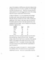
The following -tabu lation shows at what right aseention (ItA.) the
projected planet should Clppear when its indicators are CIt the given
heliocentric longitude (H. Lo)
PLANET
H. L.
Mercury
270
R.A.
-6
Venus
90
18
Mars
90
6
Jupiter
270
18
Saturn
270
18
Only MercurY and Venus lie along the solstieial axis of the instrument Qnd shou Id show exactly on the hour e irete. The superior
analogs, being off center from this axis, should show their projected
planets a couple degrees off the proper side of the hour circle to
compensate for th is fact.
For example, the Mars analog is offset
to the left of center and the planet should be at approximately 6
hours 10 minutes R.i\.
If
CI
planet does not appear at its proper It A., loosen the rotating
mirror assembly setscrew and rotate the mirror as required before
"
retightening the setscrew. The mirror is spring loadeq to keep fhe
,
11-19
'~
6/6fJ
analog arm in contact with the wedge, so it will be necessary when making this adiustment to hold the rotating mirror
upward as it is rotated into position lest it drop downward off
the e~d of the tube.
·4.
Freeing Latitude Axis - When making adjustments to the planets,
moon, etc. and it is necessary to observe these bodies in more
than half the sky (as in noding or setting up for a particular date),
rather than run the instrument repeatedly in daily or latitude
motion it is often advantageous to loosen the latitude
C;'-'I';;'
so
that the entire instrument can be swung maRually through its
supports.
Remove the dust cover from the support block adiacent
to the extended latitude axis carrying the pole and geocentric
earth projectors.
Fixed to the large brass gear is a split shaft
collar which clamps to the shaft by means of a recessed Allen
·cap screw.
Loosening this screw slightly permits rotating the
instrument about the latitude axis.
Loosen until slight pressure
is required, but the instrument does not move freely.
Always
exert pressure on the upper central cage section - NEVER on the·
ec Iiptic plate or any componenf below the planet analogs ..
'~"'.' i..'
If the cardinal points projectors are controlled by a microswitch
actuated by a cam attached to this split clamping collar, it is
necessary to bring the instrument back to its origina I latitude
position qefore retightening the c?pscrew.
If this setting should
need correction, tighten the cap screw when the cardinal points
move to their alternate mode iust as the celestial north pole
passes the zenith.
Caution: If th is procedure is used to loosen the latitude drive
temporari ly I ALWAYS be sure before retightening that the large
6/66
11-20
I
It must
~t
ali ;lr!-:es rp.::ir.lcln ij's p0sition so that it is centered
with the drivir.g worlil gear.
fore loosening j'ha
CClP
The shaft snould be m:::rked be··
screw 1:1 the split collar.,
5. Noding the Pic~e:iS
Prior noding d ti-:e I~oon cmd 50:';';/)8 of \"he sun will have utilized certain proceclu,o;;;s alld concepts which are co:'nmon to the
planets.
For example, it is tne wed:;e vvithin the heliocentric
,. I whlcn
. . . .lmpo.r.s
.. 'Inc I"IrlC.lhon to th
I tsi or b't
" d e l",l;a
e pone
IS
Iongll'u
with respect tc the eclip;ic. And the projected images are observed at four places along the ecliptic - at the ends of the
plJroll'3l and transverse c:xes.
Again, a simple fabulation or-the irr:age posli"ions win prove helpful to determine the quantity and direction of correction required
at the end of e·::;c.11 axis.
The image is brought to a series of four
posii'ions on or e,!ually above or below the ecliptic and, if required, la'firvde correcl'ion is made as de:cribed in the discussion
of noding the j"j;oor;.
ere ider;;-ic.:al
)-0
"n-,e
adius;-able mirrors or. the projectors
j':lQt on the sun and are (Jdjusted in the same man-
ner.
. IOi'18!;'u
. d e Tvr
(" i'r:e a:.;cenol,. ng noaes tor t h e p Ianets
' he I"loce:itr'IC
Tne
I
-
eire giver. in t:-,~: Ep~emerjs, page 176, end are prir.ted on the band,
which surr0ui,d:; ~he
:"OP
of 'lhe
h
CI1Sj8
se(,";i';oil of the instrument, ad-
. I h',e
' p.o'let
!
•In quesTion.
"
Th e
.lQcent \'0 t,-;e
ISWI;r:;."';8!;
' I
, •
W:1IC
• c()m'~'o
descending node is 180 0 away I and may be u:;ed where it is more
convenient and acc.un':.lh~
:'0
do so.
More accurate settings are
possible wr.en usit;8 the ir;l~er dkd c'nd when the apprprlate indicat.,rs cm~ tcward th6i' o;.;j'side of the instr",ment.
: 1,-21
6/66
The ascending and descending nodal positions on the wedges are
. indicated at the appropriate heliocentric longitude values by
scribed lines or by small dots on the sides of the wedges.
Because it is the wedge which defines the inclination of the orbits of th e planets, and the arm rotates around the wedge, it is
in all cases the brass arm pointer which must be related to the
nodal positions on the dial.
This pointer hanges below one end
of the arm and its point is close to the dial for easy reference.
A thorough understanding of the analogs will assist in the remaining adiustments - noding and setting up the! nstrument for
a specific date.
(a) Each is an analog of a portion of the solar system and the
-
y
th ree significant positions represent those of the sun, earth, and
a planet.
In all cases the sun l s position is at the center of the
arm, wedge, and inner heliocentric longitude dial.
The arm
rotates about this center, carrying a cylindrical magnet with
a cupped outer end in which rides a steel ball.
This ball, being
the nearer planeh::;ryelement to the sun, represents the position
of the nearer of the two planets under consideration for a specific aralog.
Thus, for Mercury and Venus the ball represents
those planets, because the earth is far·;"her away from the sun.
For the Jhree superior planet anplogs the ball represents the
earth, for rhe earth is nearer the sun. The third significant
position is Gt the cent.::.r of th e analog and is seen as a post
which protrudes from the center of the large thick colored plate
and is cor.tinued downward by the tube-and-rod assembly which
terminates in the ro·tating mirror.
This position is farthest re-
moved from the sun and is therefore the earth on the Mercury
6/66
11-22
and Venus analogs and the planet for the superior analogs.
Observation of the analogs while running will show that the
ball rotates around the sun and both these elements around the
plate post.
The arm pointer always indicates the heliocentric
longitude for the ball - whether it represents a planet or the
earth.
The plate or post longitude is indicat~d by a scribed
cylinder or two small holes located near the perimeter of the
plate and always maintained in a positioQ:,adjacent to the
dial.
A moment1s reflection on the foregoing and a little practice
will infallibly tell the operator which indicator he will set
for which element of the solar system for a given analog.
example:
For
/.
Mercury Analog:
Ball - Arm Pointer - Planet
Post - Plate Indicator - Earth
Mars Analog:'
Ball - Arm Pointer - Earth
Post - Plate Indicator - Planet
(E:)
The outer dial on the plastic dust cover of each analog is a
duplication of the dial within and is provided to make setting
easier when the internal indicators are in positions which are away from the operator and difficult to read.
The brass pointer
fixed to the plate duplicates the reading of the plate indicator;
the scribed flat a,luminum pointer duplicates the setting of the
inner arm pointer.
(:.) The 1/16 11 diameter brass line-of-sight rod passes through
the steel ball and terminates in the central post, thus at all
times duplicating the observer's line-of-sight from the earth to
a planet at any time for which the analog has been set up.
11-23.
The
6/66
tube and rod assembly transmit this line and orbital inclination
to the rotating mirror which in turn reflects each planet's beam
of light from the projector onto the dome.
~)
The individual impulse switches for the analogs impart full
speed forward annual motion to the entire analog mechanism so
that earth and planet indicators move forward on the dials.
For
the superior planets the accompanying knurled knobs drive only
the planet portion of the system and the earth indicator remains.
stationary.
This is also true for many instruments with respect
to the inferior analogs, but a recent development utilizes a
switch' and motor drive for the planet as well.
The operator
can thus bring either earth or planet indicator to any setting,
).
but in the superioi anc!ogs he IT;ust first set the earth by switch,
then the planet by hand.
Noding the superior planets is somewhat easier, so it is best to
adjust these first. . Drive the Saturn analog arm pointer (earth)
to 113 0 or 293 0 on the dial.
At these points the arm lies across
the wedge so that- the projected planet should be on the ecliptic
(zer.o latitude).
Turn the planet knob to bring the projected plan-
et to the four positions along theprojected ecliptic which are at
the ends of the parallel and transverse axes (when the beam from
the rotating mirror is parall,el and transverse to the optical axis
of the projector).
Tabulate the four latitude positions of the
planet as described above in the discussion of moon noding.
If
it is on the ecliptic at all points, no correction is required.
If
not I correct by adjusting the projector mirror (see sun adjustment
above). When all four points have the same latitude, adjust the
latitude to zero.
6/66
Procedures for Jupiter and Mars are identical
1!-24
e),cept-rhat the node values are 100 0
-
280 0 and 49 0
-
229 0
and the planel's will be projected at different points along the
ecliptic beca:.Jse their projectors lie at different ang les on the
instlvment.
As n07ed above, the instrument may be driven in
daily a:1d/or latitude motion, or the lat'itude axis may be
loosened in order 10 observe the ecliptic and plane-rs well above
the horizon.
In instruments having motorized earth drives for the inferior
planets the same noding technique is used.
However, iJ is the
planet drive which brings the arm pointer to the node values
(48 and 228 0 ror Mercury and 76 0 and 256 0 for Venus) and the
earth drive then brings the projected planets tothe desired
points along the ecliptic.
,,/,
For those instruments having manual inferior planet drives before
noding see Addendum No.1 at the end of this section.
B:
Setting the instrument for a Date
1. ' The Sun
Having sek:crl8d a date for which the instrument is to be set, drive
daily motion to put ~'his portion of the projected ecliptic above the:
horizon.
Actuate the sun switch on the instrument or the annual
motion switch on tne console unti I the sun resets on that date.
fi rsf of each month is ma r~ed by a line.
The
Oth er dates will be est i - ':
mated with reference to these lines or all elements can be set for
the first of a monf~" and then the entire system driven in annual
motion to any other selected dote.
Bear in mir:d tnot all annual
motion mOTors are tied together electrically so thaJ when the annual
motion switch is used all elements are driven simultaneously to their
proper places in the sky.
This means tha~'once one element - sun,
li-25
'6/66
moon, or any planet - has b;~en sel' for a date, all others must
be set by individual swi;-ch and/or mC.irrual knob.
2. The Ephemeris
For subsequen-[ setting of the meon and planets it will first be
necessary to refer to the Ephemeris or simi lar SOL.'rce and it is
advisable to uSe a tabu lotion sim i lor to the one sent with the
instrument.
For many years the Ephemeris page numbers have
remained pradiccdly unchanged and are given for quick refw;~',:' aa~h
erence. A current copy is supplied
instrument.
Be-
cause the supply is often exhausted early f it is suggested that
copies for subsequent years be orde ed from the printer several
months in advance.
3. The Moon
:;./
/
.
'
Beginning on Ephemeris page 68 is a table which gives the apparent right ascension for the moon for any hour (use zero hour)
of the date chosen.
The proiected moon is driven by its right
ascension switch to the proper right ascension as related to the
. projected ccordinares.
Beginning on page 52 is a table giving the moon's apparent
latitude for the chosen datei again use zero hour.
ting tabulation record this latitude.
On the set-
By referring backward
and/or forward in time determine whether the latitude is increasing or decraasing and indicate this on the setting table.
Tu m the knob over the moon ana log to drive the wedge unti I
t~e moo:! r80ches its proper latitude.
Ba sure -/'o turn the wedge
forward so t~at ~he divisions on the wedge dial are ascending.
Note that in order to el iminete geCir backla.'.ih effects, all elements are set originally in the forw~.Hd direction. When annual
6/66
li-26
p
.~-
motion is driven forward, there will be no backlash in the gear
trains. Reverse drive will introduce varying amounts of backlash.
If, in setting an analog, the operator inadvert.ently overshoots a
correct setting eithergo all the way around again (if a motor-
driven setting) or bock up (if e monuel setting) well past the
setting and again approach it in the forward direction. When
.uncertain which way to tu n a knob for lIforward Jl , observe the
direction in which the dial divisions pass the indicator.
After the moon is set in right ascension and latitude, return to
the three-position moon phasing switch on the console.
switch has three positions.
This
To the left all electrical circuitry
to the phasing motor is broken and no phasing will result under
any circumstances.
!n the central or upright mode the moon
phases automatically .in synchronization with tl:Je balance of the
annual motion system.
In the righthand position the switch
drives only the phasing motor.
In the central or automatic pos-
ition the DC braking voltage is applied to one motor winding
whenever the annual motion switch is off.
After phasing the
moon malTualiy, turning back tq the second position thus stops
the phading drive iristantly.
If the switch is returned rapidly
from position three to one, there will be no braking and the
drive will coast slowly to a stop.
The final steps in setting the moon are: first phase it manually
(third or full right switch position) to first or third quarter and
observe the al ignment of the moon!s terminator with relation to.
the projected ecliptic.
It must be perpendicular to the ecliptic
and the lower right quadrant must be the brightest.
Driving the
dove prism switch (SlMoon Rotation l1 ) on the instrument will ro-
11-27
6/66
tate the moon to meet these conditions. The last step is to observe the moon1s position with respect to the sun and use the man ual
phasing switch to bring it to the correct phase.
4. Setting the Planets
Refer to the Ephemeris and complete the setting tabulation with
the following data:
~
Earth Setting
From the table beginning on page 18 record the sun's
longitude for the selected date.
centric longitude.
This datum is geo-
Pdd or subtract 1800 from this
figure to derive the earth's heliocentric longitude.
Drive the planet analogs individually by switch un-
til this value is set at .all earth indicators. For the
inferior planets this is the plate indicator; for the
superior planets it is the arm indicator. The alternate indicator next to the dial located on the dust
cover may be used but are not as accurate as those
within.
<!:)
Planet Setting
From the Ephemeris tables on pages 160 to 175 record
the longitude (heliocentric) to the nearest degree for
each planet for the date chosen.
Interpolation may
be necessary for the superior planet data, depending
upon what date is selected for setup.
Drive the analogs individually to these values. Move
forward to the proper setting in all cases so that gear
backlash is consistently eliminated for all analogs.
If the correct value is inadvertently passed, back up
6/66
11-28
.,
and come forward again or, in the case of the
motor-driven planet indicators, go on around again
to the proper setring.
The inferior plar:ets are
driven manuc:lly or by moto~, depending upon the,
,model of the instrumE:nt.
resents the planet.
The arm indicator rep-
The th ree superior plane'ts are
driven manually and the' plate indicator is used.
The five analogs are now set for a specific date
with all earths and planets properly positioned
about the sun and the line-of-sight rods simu'lat,:",
ing the lines or sight between the earthbound observer and the planers.
C. Fine Adjusr;ng Proiected Positions
The foregoing settings may be mode in full chamber illumination.
Referring to the tables on Ephemeris pages 178 to 217, record the
Apparent Right Ascension (to the nearest minute) for each planet
for the chose .. date.
Project the planets and coordinates on the
darkened sky and compar.e the positions of the planets with the
Ephemerides.
SOi1ledisplacements may be found due to the instru-
men!,ls circular rather than ellipJical orbits, inaccuracy of set-'
ting, e'j·c.
To Hile adjust the proieded planets to their correct
right uscensions, drive the planet portion of the analog as required,
taking care ~'hai' "this fillal, posi';iun is always' appruQched in the forward diraction.
D. Ali'ernel'e Set'ring of Plcr.ets
Steps ~ and.:. may be combined into one step if care is taken tG
understand the analogI s functions end the resu Iting projected proper
and retrograde motions on the dome.
Once step!:. has set up all
earths, the planets may be driven individually by hand or motor
11-29
6/66
as desc ribed above unti I each comes to its correct apparent
right ascension on the projected coordinates grid.
Attention
to the Ephemerides for a few days before end after the setup
date will indicate whether the planet is in proper or 'retrograde
motion.
The projected planet must be moving in the correct
direction when brought to position, and its heliocentric longitude will closely correspond to the values tabulated in step,:.,
5. Using Annual Motion
With the sun, moon, and planets set for a date and the annual
motion indicator on the console zeroed, the annual motion switch
on the console is used to drive the enti re system forward (clockwise) or reverse in time to any other desired date.
The indicator
on the console moves with the system and shows the algebraic
:,../'
,
~
sum of a II forward and reverse movements since it was last
zeroed.
Bear in mind that the all setting was done in the for-
ward direction end that when driven in reverse differing amounts
of gear backlash wi II be imparted to the analogs and sl ight inaccuracy may result in the projected positions.
This is canceled
out as soon as the system is agai n d riven forward.
6. Tie-In
Provision has been mroe to tie in the annual motion system with the
dai Iy motion d rive so that as the instrument rotates through one 24
hour day, pulses actuate the annual motion drive so that the sun
moves one degree and the moon 14° along the ecliptic in the
proper direction. To use this feature it is necessary to lift the
toggle switch on the front of the annual motion drive chassis to
the IN posi t ion.
To cali brate the tie-in system if is best to use the large dial on
6/66
iJ-30
"
the perimeter of the moon analog plate.
In the plastic dust
cover is a pointed indicator which is.. related to the diaL
any hour circle of the coordinates system to the meridian.
Bring
Read
the moon dial and be sure the tie-in switch is IN . .Advance
dai Iy motion through 360" or one day unti I the original hour
circle is back on the meridian. The m'oon dial should have advanced 1-4°.
If adjustment is necessary I a rheostat on the annual motion chassis
is used.. It is identified by a 1/411 shaft projecting from the rear
of the chassis.
Turning the adiustment clockwise increases the
duration of the pulses delivered to the annual motion system. Adlust this rheostat until the moon moves approximotely 14° during
one day.
If finer adjustment is reguired( use
/'
(2
,
similar rheostat
found on top of the annual motion switch within the console.
(Some earlier instruments have only the one tuning rheostat on the
ANI chassis .. ) Before adjusting tie-in, it is best to turn the tuning
". --.. ..rheostCll"(s) to the middle position. The tie-in feature may be eliminol"sd -at any time by moving the AN\ chassis switch to OUT.
\
"
6/66
ii-31
$I
. -" •
. :~ . 't.
",
v
ADDENPA TO SECTION II
1.
Noding of Inferior Planets on Instruments Having Manual Planet Setting Knobs
Refer to page 11-25
Earlier A-3-P instruments employ a manual setting knob for each inferior planet
rather than a mOTor drive. The same basic techniques are used in observing and tabulating the planets ' positions with reference to the ecliptic when at the ends of the
parallel and transverse axes.
By experiment it will be ascertained what combinations
of heliocentric longitude for the earth and planet will result in successively proiecting the planet to the ends of these axes.
Each time the earth Is driven by motor, the
planet indicator (on the rotating arm) must be brought manu.ally to the nodal heliocentdc longitude as indicated by the dots or s~ribed lines on the sides .of the wedge
.'
(480' or 223 0 for Mercury and 76° of 256 0 for'Venus).
Devit;:tions above or below the
ecliptic are recorded and corrected as outlined in the text for analogs which ore
driven by duol motor drive.
6/66
1l-32
,
•• ~.
, .
•
'.:.0'
.'
"".l&V'
';,t;
'f7
...
'
,;.
SECTION III
OPERATOR'S CONSOLE DESCRIPTION
AND
OPERATING INSTRUCTIONS
A.
General Description:
The operator's console is divided into two main functional
divisions:
1.
The Operator's Control Panels (Two): The vertical panel (actually it is slightly
slanted away from the operator for convenience) and the horizontal panel.
All knobs turn clockwise to the "Full On" position. All step switches turn clockwise for forward or normal motion, and counter clockwise for reverse motion. All lever
/
.
/
type switches throw forward or upward for lion" and, where double, throw to the rear
for a reverse action.
Th;~
unj·formity greatly accelerates the process of learning to know
the instrument controls •
.J
2 •. The Electronic Component Section: This second functional division is enclosed
It includes not only the electronic components, .but
within the operator's console.
all the necessary terminal strips and cables to connect the controls to power sources
cmcl th~m on to the projector instrument operating mechanisms.
As this section is completely installed and inspected at the time of the installation
of the planetarium by Spitz men and needs no further handling, we will leave the description and function of this section
to the manual division on MAINTENANCE IN,
STRUCTIONS.
The planetarium operator need not concern himself with this section
unless a malfunction occurs.
B.
(See Maintenance Section)
The Vertical Control Panel
This panel is divided into three rows of controls and a row of fuses.
Hl-l
Each control
6/66
is labelled and the labels are backlighted for emy identification in the dark.
.
,
1.
1116
a.
,
Top Row of Controls (from left to right)
DAiLY MOTION SWITCH.
This is a rcvQrsiblc, continuous action
switch which incrc::;:;es daily motion rotation of the projector instru~ent
around the dai Iy motion axis from a bore!y perceptible motion to a rate
of one rotation per minute.
The 5wikh know is turned c !ockwise for
forward r.otation and counter clockwise for reverse rotaj-jon.
The high-
er speeds are provided for quick setting of the instrument.
b. ANNUAL MOTION SWITCH.
This, too, is a reversible, continuous
action switch which, when turned clockwise, increases the forward annual
motion of the sun, moon and planets from ap?'roximate!y one year in five
minutes to one year in one minute.
Counter clockwise turning of the
knob reverses annual motion at the same rate.
-
)
c. ANNUAL MOTION INDICATOR.
'As
annual motion is performed,
either forward or backward in time, the indicator moves one division for
each year of motion. The indicator needle can be manually positioned
, by the knurled knob protruding through the face of the dial.
the needle is set on
d.
"Oil
Gene;-ally,
for the annual morion position to a preset daj-e.
LATITUDE MOTION. 'Th is is another reversible, continuous action
switch.
The instrument may be rotated continuously about the latitude
axis in either direction.
(Take care that no auxiliary projectors on the
base posts interfere).
e.
up.
CLOCK.
The clock face is lighted when the panel lights are turned
It can be quickly reset by the knurled knob protruding through the
dial face.
This clock will continue to run even when the key switch is
off •
. f. PRECESSION. This switch provided forward precessional motion when
111-2
6/66
the knob is turned clockwise and reverses this motion when turned counter
clockwise.
g.
The center posH'ion is the "off' position.
MOON PHASING.
This is
0
3-: r)Qsition switch which controls the
phasing mechanism on the moon image projector.
vides automatic phasing of the moon
motion.
CiS
The center position' pro-
the projector performs annupl
The clockwise position provides a continuous change of phase whi,le
,
. the moon remains in the same right ascension position (most useful for a disi
cussion in which the phases are named and for setting the moon).
The
counterclockwise posiHon stops the phasing disc and the moon image will
i
remain in the same phase as annual motion proceeds.
h.
SIG,NAL.
This is a single throw lever switch which is 1I0n" in the up
position of the lever.
Generally, it rings or lights a sigral so that attend"
.
I
ants outside the chamber can prep9re to assist the audience in or out of the
/
-
.
planetarium.
2.
The Middle Row of Controls
Each of these controls is a r'neostat inserted in' the circuit as labelled .. Turning
the knob clockwise increases the current flow! to maximum as it reaches the end
of its rotation.
From left to .right the controls supply regulated current to these
.
:
I
image projectors: STARS, SUN, MOON, INFERIOR PLANETS (Mercury and
Venus), MERIDIAN, COORDiNATES, ECLIPTIC, and the three CELESTIAL
TRIANGLE projectors.
3.
The Bottom Row of Controls (from left to right)
These rheostot controls operate in the same manner as those in the row above.
From left to right they supply current to the following projectors: TWlLlGHT,
GEOCENTRIC EARTH, SATELLITE, the three SUPERIOR PLANETS (Mar~, Jupiter,
and Saturn), and CARDINAL POINTS,
The balance of the row is mC;Jde up of three
I
single throw switches that supply unregulated current to the LATITUpE, POLE, and
ZENITH proiectors.
6/66
11!-3
:!
: I
:i
"
I \
I
,1
The Satellite control is unique in that it includes.a llOV on-off switch for the
motor drive and a 6V rheostat for the lamp., AS the knob starts its tLrn th~ switch
clicks on. AS it progresses clockwise the lamp brilliance increases. When turning the satellite off, be sure to t~rn the knob to its fup counterc!ockwise"P0sition
'! :
so that the switch clicks off.
•
4.
a.
I
i
Th e Row of Fuses
General: There are seven fuse holders in the row at the bottom of
the vertical panel, each labelled as to thecircuit the fuse protects.,
The fuse holder caps light up when a fuse blows as a signal to the operator that there is a malfunction in the circuit.
!
During a lecture, it
wi 1/ probably not be possible to remove the malfunction which caused
the fuse to blow" so the operator shou ld I if possible, eliminate the
part of his demonstration which requires the use of the circuit in difficulty.
If the fuse signal light is disturqing during the baLance of the
\ demonstratioh, it can be tu rned off by twisting the cap.
\\
Th,e malfunction in the circuit should be rep'aired before the circuit
'IS \pU\lnto
t ' operation again.
, I .
(5 ee M'
) Tion,
alnrenance S
e"
C
The br~wn fuse is removed by rotating the cap 1/4 turn and pulling it
and theVuse from the holde:',' The new fuse is inserted ir .the cap tube'
and the fuse and cap locked in place by reversing the removal action.
I
b. The Fuse Holders and Fuses' Used:
1. STARS: 3 ampere fuse
2. SUN AND MOON: 1 ampere fuse
3. AUX 1: 6-1/4 ampere: fuse. This circuit provides
6-volr suppjy to the satellite, geocentric earth, and
twilight projectors.
4.
PLAN ETS: 3 ampere fuse
I
Ii
6/66
11:-4
c.
5.
AUX 2: 6-1/4 ampere fuse. This circuit supplies
6-volt supply to the coordinates, ecliptic, astronomical triangle, and the cardinal points projectors.
6.
AUX 3: 6-1/4 ampere fuse. This circuit provides
115-volt supply to the moon phasing, precessional
motion, and satell ite 'motors.
7.
MAIN: 10 ampere fuse. This circuit provides electrical supply to the entire instrument except the clock.
Key Switch: Th is key operated switch provides 115-volt supply to the
entire instrument except to the cove lights and,:the clock.
C.
The Horizontal Control Panel
This panel is separated into two side panels by the red transparent reading light
panel.
The most obviou's feorure of each side panel is the large, circular knob
of the cove lighting controi.
1.
Cove Light Controls - Yellow-'and Blue
The control knobs operate the large capacity variable transformers
mounted on t;,e pla;forms under the horizontal panels.
The left control knob is labelled YELLOW and controls the strawcolored lumiline lamps in the cove.
The right control knob is labelled
BLUE and controls the moonlight blue lamps in the cove.
2.
Pointer
The gun-like pointer projects the arrow which is an essential means of communication between the operator and audience. The pointer plugs into a
receptac Ie in the upper right surface of the kneehole on the operator's side
of the console.
The brightness of the projected arrow is controlled by the
rheostat labelled POINTER located near the forward left corner of the reading
light panel.
3.
Panel Lights
Red panel lights are found behJr.d the vertic,,1 panel and under the two side
11l-5
6/66
sections of the horizontal panel. They furnish the illumination for
backlighting the engraved captions under the controls of all panels~
.
-
,
The brightness of this backlighting is controlled by the rheostat
"
C
,
lobe! led PANEL LIGHTS at the near left c:orner ~f the reading light
panel.
4.
Reading Light
The reading light panel provides a low level backlighting of lecture
notes when it is necessary to refer to them in the darkened planetarium
chamber. The brightness is controlled by the rheostat labeled READING
LIGHT in the near right corner of the reading light panel. The red
light provided does not appreciably affect the dark adaptation of the
eyes.
5.
Cardinal Points
j
The four compass points, N, E, S, and Ware projected onto the dome
,/
from the cardinal point projectors mounted on the top of the pedestal.
, The cardinal points are turned "onl1 by a forward throw of the swi tch
just to the right of the reading light panel marked CARDINAL POINTS.
(
Tne brightness of the projected image is varied by the rheostat knob at
the center of the bottom row of controls on the vertical panel labelled
CARDINAL POINTS.
Each projector projects either of the two cardinal points 180 0 aport,
that is, NS, EW, SN, <Dr WE. When sufficient latitude change has been
made to require reversing the points,on the dome, a microswitch at the
end of the latitude axis automatically switches the circuit to the reversed
set of proje;:tion letters on the projectors. The microswitch operating
position can be adjusted to make the reversal of cardinal points suit your
local or desired latitude situation.
6/66
1!i-6
.,~
-------'--------..,---,---"'''---- ..
-'---'--~
..--''-------------- - -
,---,-"--.-----'---'--~--------
I
'L
6.
rr
In Use" or I1Wait ll Switch
This switch is used to tum on a lighted sign outside the planetarium
chamber. When lighted; this sign indicates to visitors that a show is
in progress an'd that the chamber should not be entered. The switch
is located at the forward, right corner of the horizontal panel.
7.
Lever Switches
Along the forward edges of the two horizontal panels are ten switches
which control the correspondingly marked sockets on the instrument base.
Those for the Proiection Orrery, Meteor, Bolide, Comet, Eclipse, Aurora,
and Auxiliary are single-throw double-pole.
On one side of each is 110V
for motors and on the other 6V for lamps.
The two Constellation switches ~re double-pole double-throw and control
four 6V circuits for lamps only~
/,
An eleventh switch. to the extreme right marked
IN USE is single-throw
and controls a 110V circuit to the terminal strip within the console.
From
this point it may be used to control a fixture at the entrance.
8,
RIP or Spare Powerstats ,
lmmediately forWard of the panel lights and reading light rheostats are two
knobs controlling ., two powerstats.
Where Room Illumination Projector rings
;
are supplied around th.e instrument base in lieu of cove lights on the dome,
these are the controls.
If cove lighting is supplied, these powerstats may
be used to contro[ 110V auxilialY proiectors.
termina; strip within the console.
Their circui ts lead to the
Note that the capacity of each power-
stat is 1.75 amperes.t. .
9.
Electrical Drawings
A complete set of electrical drawings is suppl j ed with' each instrument.
These
wi II be helpfu I in troubleshooting electrical problems and in making use of
6/66
!U-7
.,>;.
")
......
the auxiliary controls discussed above. The operator should consl.!lt the:;c
drawings before connecting to the terminal strip inside the console or using
the auxiliary sockets ~n the instrument base.
D.
(
Additional Console Controls
On either side of the console drawer is a small sguare removable panel.
The one to the left is used when the in:;t'allation includes a slide projector.
On this panel is an ON - OFF switch to actuate the entire projector system, an electronic rheostat to control the lamp only 1 and a socket into
which the remote control cable is plugged. The fan is ON when the switch
is on and shou Id be left running unti I the lamp is cool.
The panel to the: right of the drawer is supplied with fou r blanked holes in
which the operator can mount switches to control such optional chamber
circuits as those for room lights, receptacles, or special effects.
v'
~/66
i.
111-8
.:;
SECTiON IV
MAINTENANCE
A.
Genera I Desc ription
1.
The Spitz YeC'lrly Maintenqnce Contract
A yearly maintenance and inspection service is
provid~d by the Spitz Service
Department. A !abon,ltory-trained mainten(llnc~ mcm will give your instrument a tho.rough inspection, cleaning, and will repeir or replace all parts
Write to Spitz Laboratories, Inc.
I
(H
units not up to standard.
Yorklyn, Delaware, for information on this service.
(
2. Cleaning
a.
v
I.
Dusting the Star Sphere
A soft, flexible brush of the lerge househould pGlinting variety is
ideal for dusting the perforated surface o.f the star sphere. This should
be done as often as required to keep dust from clogging the star holes.
NOTE: If it is
sUsp~~teGl that'c stcr hole has been clogged, a piece of
tracing paper or onicn skin typing paper passed over the sphere in the
susPeded area wii I reveal a partially stoflped up star hole.
Clean with
a fine wire or neeclle.
b.
Cleaning Star Sphere ~~
A smaller, soft bristled brush (of the soft, water color type) will remove
dust from the projection lenses and mirrors without removing them from
the sphere.
Lens tissue rollE:d into a small tube wi II genE:rally remove any· .fi 1m t~(£lt
may collect on the lens surface.
;V-i
6/66
'D
c.
Cleaning the Planet, Sun and Moon Lenses and Mirrors
Projected image brightness is reduced when image projector lenses
and analog projection mi rr<!lrs are covered with dust or film.
The
small soft water color brush previously mentioned is ideal for c leaning these lenses and mirrors. The mirrors are front surfaced anQ,
even though overcoated, should be cleaned with lens cleaning
tissues or soft brushes to prevent scratch ing the surfaces. Water
0r alcohol, or
d.
€I
mixture of the two are effective cleansing agents.
Pedestal and Control Console
The broad wood, plastic and painted surfaces of these components
should frequently be dusted. A damp cloth, wet with water and
19
mild soap solution will remove fingerprints and film when necessary.
Wood surfaces will benefit from a periodic waxing with paste wax.
(Care shou Id be taken to keep water and oth er c leaning agents from
entering the receptac les (;md other devices mounted on the pedestCllI
and cons0le.
3.
lubrication
In general, a minimum of 1ubrication is required, and lubrication, except in the
few places listed, is to be avoided.
a. Mechanical Horizon Cutoffs
These sh ield-like devices cut off the projection be lew the horizon by
the sun, moon, and planet analog mfrron>.
They depend upon a free ...
swinging motion to perform properly.
Once a week the horizon cutoff bearing around the analog shaft
should be dusted and blown clean. Once a month, after the cleGmins operation, a small drop of lightweight machine oil should be
placed on the bearing.
IV-2
6/66
,
.:
.. .. :
~
"
• _ o·
'.,
.
.~
",
:....
':., " .',...,~. .9,:'.
,
"
.'
.
; •e
.
b.
Daily Motion and Latitude Motion Gear Trains
These gears are located at the ends of the latituqe axis under easily
removed covers.
Every six months they should be inspected and a
good grade of light grease added when necessary.
c.
Doily Motion Belt Drives
This mechanism is enclosed in a rectqngular housing at the center
of the latitude axis. The cover is labelled: REMOVE COVER TO
LUBRICATE.
Once a year inspect the belt for wear, and replace
if necessary.
Then lubricate the gear train with a lightweight greast.
4. Bulb Replacement
a.
A-3-P Prime Sky Light Source Replacement
The light source cup assembly is completely rerooved by lifting the
;'
hook-like hangers at the top of the cup ,from the pins at the ends of
the yoke which supports the cup.in the center of the star sphere. Access to the light source Is through the round door in the star sphere •...
Temporarily replace the Prime Sky light source with the incandescent·
spare light furnished with the instrument.
(
Telephone, telegraph, or .
write Spitz Laboratorie~ for a replacement.
When installing the replacement Prime Sky light source cup, match up
to the color code red mark on the cup with the red wire,· or red painted
yoke arm, to maintain polarity.
The red coded uplusll side of the light
source cup hanger will not fit ov~r the collar on the IInegative" yoke
arm.
b.
A-3-P Incandescent Star Bu Ib Replacement
Remove the bulb cup from the yoke arm pins by lifting and guiding the
slots in the cup hanger hooks off the pins.
Remove the prefocused GE
1637 bulb by turning the twist-lock base counterclockwise. Insert the
6/66
IV-3
.... ;
...
,
'\'.
. .,
.
;'
new bulb by reversing the process and replace the cup on the star sphere
yoke.
The lamp flange should b~ painted or inked .to prevent excess re"
flec:tionli .
On 60me older instruments a GE 1600 bayonet-based bulb was used.
it the cup could not be removed from the yoke;
On
S? it is necessary to re-
move the. star sphere itself from around the light cu'p in order to replace
.
the bulb.
Four knurled screws hold the star sphere to its base.
The
liphere must be guided outward (north) as well as upward to follow the
anels of the yoke.
Some flat black paint or ink from a metal marking pen eliminates reflection from the bulb base - a reflection which could cause double projection resulting in fuzzy stars.
c.
Sun, Moon, and Planet Bulb Replacement
1!
Remove the lamp assembly and replace with a new GE 261 pfemounted bulb assembly - rated for 1,000 hours of operation.
2, . On older instruments the prefocused GE PR 12 bulb
,is used .
It
is inserted base-up in the image projector receptac Ie with the
. fi lament placed towards the .front of the projector! . Tighten
the aluminum cap in place and hold a piece of wh ite paper
close to the projector mirror to examine the prolected mament ..
image.
It shou Id make a bright, U-shaped and well centered
image.
If it does not, tum the bulb or replace with another
bu Ib unti I
C!
good fi lament image is projected.
ine the image projected onto the dome.
Now, exam-
On projectors using
achromat lenses in the end of the barrel, if it is a little fuzzy,
turn the projeC'for lens in or out unti I the image becomes sharp.
{Actua Ily, some operators prefer a slightly fuzzy image to add
to the rea Iism of the projected planet.
IV-4
....
6/66
d.
Zenith, Pole, Latitude, and Satellite Projectors
Follow the same procedure as with the planet" projectors to replace 'the "
the PR 12 bulbs used in these projectors.
e.
Meridian and Geocentric Earth Projector Bulbs
To replace the PR 12 bulbs in these proiectors, IQosen the setscrew which
holds the bulb extension tube ill"place.
the t0be'cap.
Pull out th~ tube and unscrew
Before tightenIng the setscrew, anq after replacing the
bulb and extension tube, furn on the projector and checkth~ placem~nt ..
of t~eproiection with respect to other celestial reference points •. Often
a
slight turn ·of the bu lb exten:>ion tube will make a better fi Iqment a-
lignment and produce a sharper projected jrnage ..
f.
The Coordinates Projector Bulb
Loosen the setscrew in the.. bese at the bottom of the froiector and pull Qt,Jt .'
the bulb extension tube.
Loosen the cop cnd repl9lce with a new PR12
bl.llb. To properly position the projected coordinptes~turn on the stars
and the coordinates projector. Move the bulb extension tube in and out'
until the 5 hour, 30 minute R.A. and 0 declination are on the star
Mintaka in Orion .. Ch~ck to see that the Vernal ond Autumnol Equinoxes
fall. at 0 and'12 hours on the celestiole~uator •.
g.
The Ecliptic Proiector Bulb
The coordinates proiector is fi rst removed and the bu Ibis replaced in the
some manner as for the coordinotes proiector. Tealign the projected
ecliptic, turn on the ecliptic projector and the sun aJ"ld mo~e the bulb ~x- .
tension tube in and out until the ecliptic line fqlls on the sun.
h.
Astronomical Triangle and Twilight Proi~ctors
j
These projectors use the GE 605 screw-base bulbs. The bulb is reached
th rough the round ports cover~d with hinged round dqors in th"e sides
the triangle projectors.
On the twilight projector the bulb screws into
.
,,;'
.
6/fJ6 '
IV-~
,','.
I
•
.'
'.r.;:
,
"
of
'\t.
the end of the bulb extension tubc which is held in place with a setscrew.
The bulb fo the twilighj" projector is red gelatin coated.
B. Mal functions - Symptom ..• Cause .. , Remedy
1.
No Power to the Operator's Console
Possible Cause and Remedies:
a.
Planetarium chamber main power off: Perhaps a fuse blown.
If not,
a switch inadvertently thrown on the circuit breaker panel.
Have
electrician deiermine cause and repair.
b.
Key switch on console ::-" ;"ned out:
Replace key switch or tempor-
ari Iy connect both wi res to the same terminol screw on the back of
the switch.
c.
MQin power circuit fuse burned out ~ Lighted:
Replace lO-amp
I
fuse.
•
If it goes out Clgain, check for short in the ll0-volt circuit
or an overlosd to the -instrument an~ repair.
2.
No Projected Image from an Instrument or AuxiliGlry F'roiector
a.
If the control panel fuse in the circuit in question has not burned out,
the bulb hCls probably burned out or is making a poor contact.
?Iece bulb or clean bulb and projector contacts.
Re-
Be sure bulb re-
ceptacle collar is fC:.lstened firmly in place in the projector barrel.
If not, twist the collar back to the position wr..:..:e; lead-in wires cannot short out I!lnd giue in place with epoxy cement. A short in the
,If the short cannot be located and re-
projector wi II blow the fuse.
~aired,
3.
P~H~rly
return the projector to Spitz for a replacement.
.rrojected (Fuzzy) Star lmeges
a.
Reflection from bulb base: Coat base with dull black paint or ink.
b.
Du:;t clogged stc:r holes: Clean.
6/66 - :
iV-6
e
:'.:;
.~.
11&
"',
c.
Humidity wrinkled color fi It'ers on bright stars~ Replace star lens, assembly or, on older instruments, replace fi Iter only.
4" Planets or Moor. - R'Jn out of Proper Synchronization
Run a synch ronization test on the suspected planet, or all the planets, sun and
moon.
With the electrical drives bring planets, sun and moon up to the meridian,
driving in forward motion always.
(With outer planets save time by bringing planets
close to the meridian with knobs and finishing with electrical drive).
year forward in time with annual motion control.
Stop.
Now, drive a
Drive a year and
CI
month
or so back in time, and finish by driving the planets to the meridian in forward motion.
This will reveal a planet, sun, or moon that is not moving properly, for it will not
come back to the meridian with the others.
Possible Causes and Remedies:
a. The clutch on the superior planets or the moon knob shafts could be
slipping.
Turn the knob to detect slippage.
loosening the setscrew on the clutch nut.
tighten the setscrew.
Tighten the clutch by
Tighten the nut and
(All are located on the th readed portion of
the knob shaH).
On the moon double motor drive, check to see that the setscrews
on the gears connecf'ing the two motors to the analog drive are not
loose, causing the gears to slip.
b.
Ball is not moving freely on the line-of-sight rod: Clean rod with
fine crocus cloth and lubricate lightly with light machine oil.
c.
Lack of 45-volt D.C. braking voltage.
moon (and precessional motion) to coast.
Causes planets, sun and
This coasting is most
easi Iy detected in the srar sphere precessional motion: Check fuse
IV-7
S,.
6/66
. '1 "" -.'
\
....
on annual motion speed control chassis.
blows again, ask Spitz for
d.
If none
Q
Replace, if blown.
If it
replacement chassis.
of the above is found to be the cause of improper annual motion,
replace the motor on the unit which does not perform pro(l>erly in the
synchronization test.
motor desired,
dS
{Furnish the name of the planet, sun or moon
their lead-in wires from the terminal strip to analog
mounting position dre of different lengths,.
It may be more convenient
for you to replace the whole analog.
5. Moon Image will n(J)t Remain
Pro~erly Aligned with the Ecliptic
«
r
A line drawn between the poles of the moen sheuld remain nearly perpendicule&r to
the ecliptic.
If it does not, the fault lies with the dove prism mechanisms.
Possible Causes and Remedies:
a.
The bearing around the dove prism tube is dirty or" not properly
lubricated, causi~ too much of a drag on the dove prism drive
motor.
b.
Clean and lubricate., or replace the mechemism.
If the bearing moves freely, the rauft is with the drive motor.
Re-
place the motor.
6. Slippage or Jerky Motion in Dally or Latitude Motions
t
I
(On recent instruments be sure that the daily motion tie-in switch en the side Qf
the DM- LM chassis is in the Uout ll position before checking dGli Iy motion).
a.
Open the pedestal door and weJtch the motor for the drive in question to see if it is performing smoothly.
If not, check the brushes
and replace if badly worn or, if necessary, replace the mot0r.
b.
Next check to see that all the setscrews Tn the finke:lge between the
motor and gear train are tight. This is the most fr~9uent cause ef
6/66
IV-8
.,
..
slippage.
,
Then check the setscrews in th~ gears
the gear trains
at the ends of the latitude axis.
For daily motion, if these efforts do not correct the slippage, re-
c.
move th e cover from the daily motion drive boxsurrounding the
daily motion axis on the latitude axis.
screws Qn the drive mechanism.
Check the belt and the set-
lubricate the drive gears.
If jerky da; Iy motion persists, replace the drive belt.
d.
7. Dai Iy Motion or latitude Motion Drives Fai I to Provide Speed Changes
a. Check daily or latitude control switches for burned out contacts.
Replace.
b.
Check the drive motors for worn out brushes.
Replace or replace
motor.
c.
If the switch and motors are in good shape and the DM-LM chassis has
blown a fuse and continues to blow fuses when replaced, order a replacement chassis from Spitz.
C. ORDERING REPLACEMENT PARTS OR UNITS FROM SPITZ
Address:
Spitz lobolotodes, Inc.
Yodd)'n, Oelawell e 1973ts
Telephone:
Area Cede: 302 239 5212
Telegraph:
As above.
Call, telegraph or write Spitz laboratories, Inc. to request a replacement part or
unit. Give a complete description of the unit (name, location and use) and describe
the trouble as completely as possible. State the urgency with which you need the replacement (this determines the method of shipment to you).
At the same time, carefully pack the part or unit from your instrument and send it
to Spitz laboratories so that you can receive credit on the exchange.
6/66
IV-9
"
..
",.
"
",'
'
,
.
'
".1
.
.
,
."
.
'
" ...
@
. ,\.
?..
.
'"
,!t
0,
SPITZ SPACE SYSTEMS, INCa
u.s.
ROUTE 1
CHADDS FORD, PENNSYLVANIA 19317 U.S.A.
(215) 459-5200
TELEX / TWX: #710 760 0100 SPITZSPACE
XENON ARC LAMP WARRANTY
The Xenon Arc Lamp is guaranteed for 30 days from date of
shipment against defects in material and workmanship.
_Any
lamp which fails to ignite or otherwise becomes inoperable due
to defects in material or workmanship will be replaced if returned within the warranty period.
The entire· obligation of
Spitz Space Systems under this warranty is to replace defective lamps or, at its option, to credit the purchaser.
{-'.
This
warranty is in lieu of all other warranties whether expressed,
implied or statutory including implied warranties of merchantability or fitness.
It extends only to buyer when purchasing
directly from Spitz Space .systems, Inc.
It is suggested that the lamp be installed and tested
immediately upon receipt by the customer.
WARRANTY
t
A 123417 A __~_,~