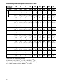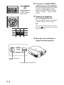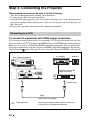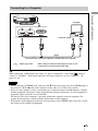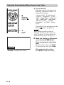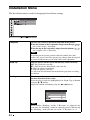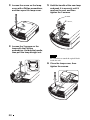
1
4-208-637-11 (2)
Video Projector
Operating Instructions
VPL-HW20/HW20A
Sony Corporation
Printed in Japan
© 2010 Sony Corporation
WARNING
To reduce the risk of fire or
electric shock, do not expose
this apparatus to rain or
moisture.
To avoid electrical shock, do
not open the cabinet. Refer
servicing to qualified
personnel only.
THIS APPARATUS MUST BE
EARTHED.
AVERTISSEMENT
Afin de réduire les risques
d’incendie ou d’électrocution,
ne pas exposer cet appareil à
la pluie ou à l’humidité.
Afin d’écarter tout risque
d’électrocution, garder le
coffret fermé. Ne confier
l’entretien de l’appareil qu’à
un personnel qualifié.
CET APPAREIL DOIT ÊTRE
RELIÉ À LA TERRE.
WARNUNG
Um die Gefahr von Bränden
oder elektrischen Schlägen zu
verringern, darf dieses Gerät
nicht Regen oder Feuchtigkeit
ausgesetzt werden.
Um einen elektrischen Schlag
zu vermeiden, darf das
Gehäuse nicht geöffnet
werden. Überlassen Sie
2
Wartungsarbeiten stets nur
qualifiziertem Fachpersonal.
DIESES GERÄT MUSS
GEERDET WERDEN.
For the customers in the U.S.A. and
Canada
WARNING:
Using this unit at a voltage other than 120 V
may require the use of a different line cord or
attachment plug, or both. To reduce the risk
of fire or electric shock, refer servicing to
qualified service personnel.
For the customers in the U.S.A.
This equipment has been tested and found to
comply with the limits for a Class B digital
device, pursuant to Part 15 of the FCC
Rules. These limits are designed to provide
reasonable protection against harmful
interference in a residential installation. This
equipment generates, uses, and can radiate
radio frequency energy and, if not installed
and used in accordance with the instructions,
may cause harmful interference to radio
communications. However, there is no
guarantee that interference will not occur in
a particular installation. If this equipment
does cause harmful interference to radio or
television reception, which can be
determined by turning the equipment off and
on, the user is encouraged to try to correct
the interference by one or more of the
following measures:
- Reorient or relocate the receiving antenna.
- Increase the separation between the
equipment and receiver.
- Connect the equipment into an outlet on a
circuit different from that to which the
receiver is connected.
- Consult the dealer or an experienced
radio/TV technician for help.
You are cautioned that any changes or
modifications not expressly approved in this
manual could void your authority to operate
this equipment.
All interface cables used to connect
peripherals must be shielded in order to
comply with the limits for a digital device
pursuant to Subpart B of Part 15 of FCC
Rules.
If you have any questions about this product,
you may call;
Sony Customer Information Service Center
1-800-222-7669 or http://www.sony.com/
Declaration of Conformity
Trade Name:
SONY
Model:
VPL-HW20/HW20A
Responsible party: Sony Electronics Inc.
Address:
16530 Via Esprillo,
San Diego, CA 92127
U.S.A.
Telephone Number:858-942-2230
This device complies with part 15 of the
FCC Rules. Operation is subject to the
following two conditions: (1) this device
may not cause harmful interference, and
(2) this device must accept any interference
received, including interference that may
cause undesired operation.
For the customers in Canada (for
VPL-HW20)
This Class B digital apparatus complies with
Canadian ICES-003.
Pour les clients au Canada (pour
VPL-HW20)
Cet appareil numérique de la classe B est
conforme à la norme NMB-003 du Canada.
For the customers in Europe
The manufacturer of this product is Sony
Corporation, 1-7-1 Konan, Minato-ku,
Tokyo, 108-0075 Japan.
The Authorized Representative for EMC
and product safety is Sony Deutschland
GmbH, Hedelfinger Strasse 61, 70327
Stuttgart, Germany. For any service or
guarantee matters please refer to the
addresses given in separate service or
guarantee documents.
Pour les clients en Europe
Le fabricant de ce produit est Sony
Corporation, 1-7-1 Konan, Minato-ku,
Tokyo, 108-0075 Japon.
Le représentant autorisé pour EMC et la
sécurité des produits est Sony Deutschland
GmbH, Hedelfinger Strasse 61, 70327
Stuttgart, Allemagne. Pour toute question
concernant le service ou la garantie, veuillez
consulter les adresses indiquées dans les
documents de service ou de garantie séparés.
Für Kunden in Europa
Der Hersteller dieses Produkts ist Sony
Corporation, 1-7-1 Konan, Minato-ku,
Tokyo, 108-0075 Japan.
Der autorisierte Repräsentant für EMV und
Produktsicherheit ist Sony Deutschland
GmbH, Hedelfinger Strasse 61, 70327
Stuttgart, Deutschland. Bei jeglichen
Angelegenheiten in Bezug auf
Kundendienst oder Garantie wenden Sie
sich bitte an die in den separaten
Kundendienst- oder Garantiedokumenten
aufgeführten Anschriften.
For kundene i Norge
Dette utstyret kan kobles til et ITstrømfordelingssystem.
Für Kunden in Deutschland
Entsorgungshinweis: Bitte werfen Sie nur
entladene Batterien in die Sammelboxen
beim Handel oder den Kommunen. Entladen
sind Batterien in der Regel dann, wenn das
Gerät abschaltet und signalisiert „Batterie
leer“ oder nach längerer Gebrauchsdauer der
Batterien „nicht mehr einwandfrei
funktioniert“. Um sicherzugehen, kleben Sie
die Batteriepole z.B. mit einem
Klebestreifen ab oder geben Sie die
Batterien einzeln in einen Plastikbeutel.
For the customers in Taiwan only
3
Table of Contents
Precautions ......................................... 6
Location of Controls
Front/Right Side ................................. 7
Rear/Bottom ....................................... 8
Remote Control .................................. 9
Connections and
Preparations
Projecting
Projecting the Picture on the
Screen ...............................................28
Turning Off the Power ................29
Operating the BRAVIA Sync
Compatible Equipment with the
Remote Control of the Projector ......30
Selecting the Wide Screen Mode .....32
Selecting the Picture Viewing
Mode ................................................34
Unpacking ........................................ 10
Adjusting the Picture Quality ...........35
Step 1: Installing the Projector ......... 11
Selecting to Directly Adjust the
Desired Menu Item .....................35
Selecting Desired Adjust Menu
Items in the Order .......................36
Adjusting the Picture Using Real
Color Processing ...............................37
Before Setting Up the
Projector ..................................... 11
Positioning the Projector and a
screen ......................................... 13
Step 2: Adjusting the Picture
Position ............................................ 17
Step 3: Connecting the Projector ..... 22
Connecting to a VCR ................. 22
Connecting to a Computer ......... 25
Step 4: Selecting the Menu
Language .......................................... 26
Using the Menus
Operation through the Menus ...........39
Picture Menu ....................................43
Advanced Picture Menu ...................47
Screen Menu .....................................48
Setup Menu .......................................50
Function Menu .................................52
Installation Menu ..............................54
Information Menu .............................56
About the Preset Memory No. ....57
4
Others
About the Control for HDMI ...........58
About the x.v.Color ..........................59
Troubleshooting ...............................60
Warning Indicators .....................63
Message Lists .............................64
Replacing the Lamp and the Air
Filter and Cleaning the Ventilation
Holes (intake) ...................................65
Cleaning the Air Filter .....................68
Fitting the Lens Cap .........................68
Cleaning and the Screen of the
Projector ...........................................69
Specifications ...................................70
Preset Signals .............................72
Input Signals and Adjustable/
Setting Items ...............................75
Ceiling Installation ...........................77
Index ...............................................81
Trademark Information
“PS3” is a registered trademark of Sony
Computer Entertainment Inc.
HDMI, the HDMI logo and High-Definition
Multimedia Interface are trademarks or
registered trademarks of HDMI Licensing
LLC.
“Blu-ray Disc” is a trademark.
..........................................................................
Control for HDMI is an HDMI standard mutual
control function which uses the HDMI CEC
(Consumer Electronics Control) specification.
This projector supports DeepColor, x.v.Color,
LipSync and computer input signal of HDMI
standards. It also supports HDCP.
5
Precautions
On safety
• Check that the operating voltage of your
unit is identical with the voltage of your
local power supply.
• Should any liquid or solid object fall into
the cabinet, unplug the unit and have it
checked by qualified personnel before
operating it further.
• Unplug the unit from the wall outlet if it is
not to be used for several days.
• To disconnect the cord, pull it out by the
plug. Never pull the cord itself.
• The wall outlet should be near the unit and
easily accessible.
• The unit is not disconnected to the AC
power source (mains) as long as it is
connected to the wall outlet, even if the
unit itself has been turned off.
• Do not look into the lens while the lamp is
on.
• Do not place your hand or objects near the
ventilation holes. The air coming out is
hot.
On preventing internal heat buildup
After you turn off the power with the I/1
(ON/STANDBY) switch, do not disconnect
the unit from the wall outlet while the
cooling fan is still running.
Caution
The projector is equipped with ventilation
holes (intake) and ventilation holes
(exhaust). Do not block or place anything
near these holes, or internal heat build-up
may occur, causing picture degradation or
damage to the projector.
On repacking
Save the original shipping carton and
packing material; they will come in handy if
you ever have to ship your unit. For
maximum protection, repack your unit as it
was originally packed at the factory.
6
Front/Right Side
You can use the buttons on the control panel with the same names as those on the remote
control to operate the projector.
Control panel
Lens shift dials (1 page 18)
M/m/</, (arrow)/
(enter) button (1 page 39)
MENU button (1 page 39)
LAMP/COVER
indicator
(1 page 63) ON/STANDBY
indicator
(1 page 17)
INPUT button (1 page 28)
?/1 (ON/STANDBY) switch (1 page 18)
Note
Ventilation
While the ON/STANDBY indicator
holes (exhaust) lights in orange, the power saving
(1 page 12)
mode is on. (1 page 51)
Remote control detector
Zoom lever (1 page 20)
Focus ring (1 page 20)
Ventilation holes (exhaust) (1 page 12)
- AC IN socket
HDMI 1 connector (1 page 22)
HDMI 2 connector (1 page 22)
INPUT A connector (1 page 25)
S VIDEO INPUT connector (mini DIN 4-pin)/VIDEO INPUT
connector (phono type) (1 page 24)
Y PB/CB PR/CR connector
(phono type) (1 page 22)
REMOTE connector
Connects to a computer,
etc. for remote control
7
Location of Controls
Location of Controls
Rear/Bottom
Ventilation holes (intake)
(1 page 12)
Ventilation holes (intake)
(1 page 12)
Ventilation holes (intake)
(1 page 12)
Ventilation holes (intake)
(1 page 12)
Lamp cover (1 page 66)
Adjusters (1 page 21)
Filter holder (1 page 67)
Ventilation holes (intake)
(1 page 12)
Projector suspension
support attaching hole
(1 page 77)
8
Location of Controls
Remote Control
Infrared transmitter
LIGHT button
Illuminates the buttons on
the remote control.
?/1 (On/standby)
switch (1 page 18)
INPUT button (1 page 28)
PICTURE MODE buttons
(1 page 34)
Buttons to operate
BRAVIA Sync compatible
equipment (1 page 30)
LENS button
(1 page 18)
RESET button (1 page 39)
M/m/</, (arrow)/
buttons (1 page 39)
BLACK LEVEL button
(1 page 35)
GAMMA CORRECTION
button (1 page 35)
COLOR SPACE button
(1 page 35)
WIDE MODE button
(1 page 32)
SHARPNESS +/– button
(1 page 45)
(enter)
MENU button (1 page 39)
ADVANCED IRIS button
(1 page 35)
COLOR TEMP button
(1 page 35)
ADJ PIC (Adjust Picture) button
(1 page 36)
RCP (Real Color Processing)
button (1 page 37)
CONTRAST +/– button
(1 page 44)
BRIGHTNESS +/– button
(1 page 44)
9
Connections and Preparations
This section describes how to install the projector and screen, how to connect the
equipment from which you want to project the picture, etc.
Unpacking
Check the carton to make sure it contains the following items:
• Remote control (1) and
Size AA (R6) manganese batteries (2)
• AC power cord (1)
• Lens cap (1)
When you have purchased the projector,
the lens cap is put onto the lens.
Remove this lens cap when you use the
projector.
• Operating Instructions (this manual)
Inserting the batteries into the remote control
Insert the batteries E side first as shown in the illustration.
Inserting them forcibly or with the polarities reversed may
cause a short circuit and may generate heat.
Push and slide to open.
CAUTION
Danger of explosion if battery is incorrectly replaced.
Replace only with the same or equivalent type recommended by the manufacturer.
When you dispose of the battery, you must obey the law in the relative area or country.
Installing batteries
Two size AA (R6) batteries are supplied for Remote Control.
To avoid risk of explosion, use size AA (R6) manganese or alkaline batteries.
Caution about handling the remote control
• Handle the remote control with care. Do not drop or step on it, or spill liquid of any kind
onto it.
• Do not place the remote in a location near a heat source, a place subject to direct
sunlight, or a damp room.
10
Step 1: Installing the Projector
Installing the projector in such a location
may cause a malfunction of the unit due to
moisture condensation or rise in
temperature.
Near a heat or smoke sensor
Before Setting Up the
Projector
Unsuitable installation
Do not place the projector in the following
situations, which may cause malfunction
or damage to the projector.
Malfunction of the sensor may occur.
Poorly ventilated location
Very dusty and extremely smoky
locations
Leave space of more than 30 cm (11 7/8 inches)
around the unit.
Install in a location away from walls
Hot and humid
To maintain the performance and
reliability of the projector, allow at
least 30 cm (11 7/8 inches) between
the projector and walls.
30 cm
(11 7/8 inches)
30 cm
30 cm
(11 7/8 inches)
(11 7/8 inches)
Locations subject to direct cool or
warm air from an air-conditioner
30 cm
(11 7/8 inches)
11
Connections and Preparations
The projector displays pictures output from
a VCR or other device.
The lens shift allows you to have broader
options for placing the projector and
viewing pictures easily.
Improper use
Do not do any of the following while using
the projector.
Blocking the ventilation holes (intake
or exhaust)
Ventilation holes
(intake)
Ventilation holes
(exhaust)
15° or more
Avoid using the projector tilted at an angle
of more than 15 degrees.
Do not install the projector anywhere other
than on a level surface or on the ceiling.
Installing the projector in such a location
may result in uneven color uniformity or
reduce the reliability of the effects of the
lamp.
When installing the unit at altitudes
Tip
For details on the location of the ventilation
holes (intake or exhaust), see “Location of
Controls” (1 page 7).
Tilting front/rear and left/right
When using the projector at an altitude of
1,500 m or higher, set “Cooling Setting” in the
Setup
menu to “High” (1 page 50).
Failing to set this mode when using the
projector at high altitudes could have adverse
effects, such as reducing the reliability of
certain components.
15° or more
15° or more
WARNING
15° or more
15° or more
12
When installing the unit, incorporate a readily
accessible disconnect device in the fixed
wiring, or connect the power plug to an easily
accessible socket-outlet near the unit. If a fault
should occur during operation of the unit,
operate the disconnect device to switch the
power supply off, or disconnect the power
plug.
Positioning the Projector and a screen
1
Determine the installation position of the projector and screen.
You can obtain a good quality picture if you position the projector so that the center
of the lens is within the area indicated in gray in the illustration.
Use the values L, x and y in the table on page 15 or 16 as a guide.
Screen
*
**
* Installation position not using lens shift (x = 0, y = 0)
** Example of installation position using lens shift (x, y)
L: Distance between the screen and the front end of the projector’s lens.
x: Horizontal distance between the center of the screen and the center of the
projector’s lens.
y: Vertical distance between the center of the screen and the center of the projector’s
lens.
For installation of the projector on a ceiling, see “Ceiling Installation.”
(1 page 77)
For details on the lens shift feature, see “Step 2: Adjusting the Picture Position.”
(1 page 17)
13
Connections and Preparations
The installation distance between the projector and a screen varies depending on the size
of the screen or whether or not you use the lens shift features.
When using the 16:9 aspect ratio screen size
Screen Size
SS (inches)
40
60
80
100
120
150
200
250
300
(mm)
1016
1524
2032
2540
3048
3810
5080
6350
7620
minimum
1201
1825
2448
3072
3695
4631
6189
7748
9307
(47 3/8)
(71 7/8)
(96 1/2)
(121)
(145 1/2)
(182 3/8)
(243 3/4)
(305 1/8)
(366 1/2)
L
maximum
x
y
x
y
x
y
x
y
x
y
x
y
1840
2782
3723
4664
5605
7017
9371
11724
14077
(72 1/2)
(109 5/8)
(146 5/8)
(183 5/8)
(220 3/4)
(276 3/8)
(369)
(461 5/8)
(554 1/4)
0
0
0
0
0
0
0
0
0
(0)
(0)
(0)
(0)
(0)
(0)
(0)
(0)
(0)
324
486
648
809
971
1214
1619
2024
2428
(12 7/8)
(19 1/4)
(25 5/8)
(31 7/8)
(38 1/4)
(47 7/8)
(63 3/4)
(79 3/4)
(95 5/8)
44
66
89
111
133
166
221
277
332
(1 3/4)
(2 5/8)
(3 5/8)
(4 3/8)
(5 1/4)
(6 5/8)
(8 3/4)
(11)
(13 1/8)
259
389
518
648
777
971
1295
1619
1943
(10 1/4)
(15 3/8)
(20 1/2)
(25 5/8)
(30 5/8)
(38 1/4)
(51)
(63 3/4)
(76 1/2)
89
133
177
221
266
332
443
553
664
(3 5/8)
(5 1/4)
(7)
(8 3/4)
(10 1/2)
(13 1/8)
(17 1/2)
(21 7/8)
(26 1/4)
194
291
389
486
583
728
971
1214
1457
(7 3/4)
(11 1/2)
(15 3/8)
(19 1/4)
(23)
(28 3/4)
(38 1/4)
(47 7/8)
(57 3/8)
133
199
266
332
398
498
664
830
996
(5 1/4)
(7 7/8)
(10 1/2)
(13 1/8)
(15 3/4)
(19 5/8)
(26 1/4)
(32 3/4)
(39 1/4)
130
194
259
324
389
486
648
809
971
(5 1/8)
(7 3/4)
(10 1/4)
(12 7/8)
(15 3/8)
(19 1/4)
(25 5/8)
(31 7/8)
(38 1/4)
177
266
354
443
531
664
886
1107
1328
(7)
(10 1/2)
(14)
(17 1/2)
(21)
(26 1/4)
(35)
(43 5/8)
(52 3/8)
65
97
130
162
194
243
324
405
486
(2 5/8)
(3 7/8)
(5 1/8)
(6 1/2)
(7 3/4)
(9 5/8)
(12 7/8)
(16)
(19 1/4)
221
332
443
553
664
830
1107
1384
1660
(8 3/4)
(13 1/8)
(17 1/2)
(21 7/8)
(26 1/4)
(32 3/4)
(43 5/8)
(54 1/2)
(65 3/8)
0
0
0
0
0
0
0
0
0
(0)
(0)
(0)
(0)
(0)
(0)
(0)
(0)
(0)
Unit: mm (inches)
To calculate the installation positions
L (minimum) = 31.1781 (1 7/32) × SS – 46.1543 (1 13/16)
L (maximum) = 47.0644 (1 27/32) × SS – 42.3308 (1 21/32)
y = –1.463 × x (mm or inch) + 8.0942 (5/16) × SS
14
When using the 4:3 aspect ratio screen size
Screen Size
SS (inches)
40
60
80
100
120
150
200
250
300
1016
1524
2032
2540
3048
3810
5080
6350
7620
1480
2243
3006
3770
4533
5677
7585
9493
11401
(58 3/8)
(88 3/8)
(118 3/8)
(148 1/2)
(178 1/2)
(223 5/8)
(298 5/8)
(373 3/4)
(448 7/8)
L
maximum
x
y
x
y
x
y
x
y
x
y
x
y
2262
3414
4566
5718
6870
8598
11478
14357
17237
(89 1/8)
(134 1/2)
(179 7/8)
(225 1/8)
(270 1/2)
(338 5/8)
(452)
(565 1/4)
(678 5/8)
0
0
0
0
0
0
0
0
0
(0)
(0)
(0)
(0)
(0)
(0)
(0)
(0)
(0)
396
594
792
991
1189
1486
1981
2477
2972
(15 5/8)
(23 1/2)
(31 1/4)
(39 1/8)
(46 7/8)
(58 5/8)
(78)
(97 5/8)
(117 1/8)
54
81
108
135
163
203
271
339
406
(2 1/4)
(3 1/4)
(4 3/8)
(5 3/8)
(6 1/2)
(8)
(10 3/4)
(13 3/8)
(16)
317
475
634
792
951
1189
1585
1981
2377
(12 1/2)
(18 3/4)
(25)
(31 1/4)
(37 1/2)
(46 7/8)
(62 1/2)
(78)
(93 5/8)
108
163
217
271
325
406
542
677
813
(4 3/8)
(6 1/2)
(8 5/8)
(10 3/4)
(12 7/8)
(16)
(21 3/8)
(26 3/4)
(32 1/8)
238
357
475
594
713
892
1189
1486
1783
(9 3/8)
(14 1/8)
(18 3/4)
(23 1/2)
(28 1/8)
(35 1/8)
(46 7/8)
(58 5/8)
(70 1/4)
1219
163
244
325
406
488
610
813
1016
(6 1/2)
(9 5/8)
(12 7/8)
(16)
(19 1/4)
(24 1/8)
(32 1/8)
(40)
(48)
158
238
317
396
475
594
792
991
1189
(6 1/4)
(9 3/8)
(12 1/2)
(15 5/8)
(18 3/4)
(23 1/2)
(31 1/4)
(39 1/8)
(46 7/8)
217
325
433
542
650
813
1084
1355
1626
(8 5/8)
(12 7/8)
(17 1/8)
(21 3/8)
(25 5/8)
(32 1/8)
(42 3/4)
(53 3/8)
(64 1/8)
79
119
158
198
238
297
396
495
594
(3 1/8)
(4 3/4)
(6 1/4)
(7 7/8)
(9 3/8)
(11 3/4)
(15 5/8)
(19 1/2)
(23 1/2)
271
406
542
677
813
1016
1355
1693
2032
(10 3/4)
(16)
(21 3/8)
(26 3/4)
(32 1/8)
(40)
(53 3/8)
(66 3/4)
(80)
0
0
0
0
0
0
0
0
0
(0)
(0)
(0)
(0)
(0)
(0)
(0)
(0)
(0)
Unit: mm (inches)
To calculate the installation positions
L (minimum) = 38.1569 (1 1/2) × SS – 46.1543 (1 13/16)
L (maximum) = 57.5992 (2 9/32) × SS – 42.3308 (1 21/32)
y = –1.463 × x (mm or inch) + 9.9060 (3/8) × SS
15
Connections and Preparations
(mm)
minimum
2
Position the projector so that the lens is parallel to the screen.
Top view
Screen
3
Project an image on the screen and adjust the picture so that it fits the
screen. (1 page 17)
Note
When using a screen with an uneven surface, stripes pattern may rarely appear on the screen
depending on the distance between the screen and the projector or the zooming magnifications. This
is not a malfunction of the projector.
16
Step 2: Adjusting the Picture Position
1
Connections and Preparations
Project an image on the screen and then adjust the picture position.
ON/STANDBY indicator
Remote control
detector
4 Lens shift dials
2
5, 6
?/1 (On/
standby)
switch
Zoom lever,
Focus ring
3 LENS button
Tip
(joystick) buttons on the side
The ?/1 (ON/STANDBY), INPUT, MENU, and M/m/</,/
panel of the projector function the same as those on the remote control.
Note
Depending on the installation location of the projector, you may not control it with the remote
control. In this case, point the remote control to the screen instead of the projector.
1
Lights in red.
After connecting the AC cord to
the projector plug the AC cord
into a wall outlet.
The ON/STANDBY indicator lights
in red and the projector goes into
standby mode.
17
2
Press the ?/1 (ON/STANDBY)
switch to turn on the projector.
The ON/STANDBY indicator flashes
in green, and then lights in green.
When the ON/STANDBY indicator
flashes, “Starting...” appears on the
screen.
3
Display a test signal for
performing adjustments.
Press the LENS button on the remote
control to display the test signal.
Flashes in green for
a while (tens of
seconds) and then
lights in green.
Tip
The test signal is displayed for 1 minute.
Press the
button to clear the test signal
display before that.
4
To adjust the vertical
position
To adjust the horizontal position
18
Move both lens shift dials to
adjust the picture position.
To adjust the horizontal position
Turn the lens shift dial right or left.
The picture projected on the screen moves right or left by a maximum of 25% of the screen
width from the center of the lens.
1 screen width
Connections and Preparations
25%
25%
Top view
: Picture position when moving the picture to the left
at maximum
: Picture position when moving the picture to the
right at maximum
To adjust the vertical position
Turn the lens shift dial up or down.
The picture projected on the screen moves up or down by a maximum of 65% of the screen
height from the center of the lens.
Side view
65%
1
screen
height
65%
: Picture position when moving the picture upward at
maximum
: Picture position when moving the picture downward at
maximum
19
Notes
• The range to move the picture projected on the screen can be adjusted only within the octagon area
illustrated below. In this connection, see “Positioning the Projector and a screen” (1 page 13) as
well.
Range of movement of
the projected picture
Projected Picture
H: Width of the projected picture
V: Height of the projected picture
• When you use both the horizontal and vertical lens shift features at the same time, the distance the
picture projected on the screen moves differ depending on how much the lens shift is adjusted. For
details, see the table on page 14 or 15.
5
Adjust the picture size using the
zoom lever.
6
Adjust the focus using the focus
ring.
Zoom lever
Focus ring
20
To adjust the tilt of the installation surface
If the projector is installed on an uneven surface, use the adjusters to keep the projector
level.
Connections and Preparations
Turn to adjust.
Adjusters
Notes
• Pointing the projector at too high or too low of a tilt will result in trapezoidal distortion in the
projected image.
• Be careful not to catch your finger when turning the adjusters.
21
Step 3: Connecting the Projector
When making connections, be sure to do the following:
• Turn off all equipment before making any connections.
• Use the proper cables for each connection.
• Insert the cable plugs properly; poor connection at the plugs may cause a malfunction or
poor picture quality. When pulling out a cable, be sure to pull it out from the plug, not
the cable itself.
• Refer to the operating instructions of the connected equipment.
Connecting to a VCR
To connect to equipment with HDMI output connectors
You can enjoy better picture quality by connecting a DVD player/recorder, Blu-ray Disc
player/recorder, or PS3® equipped with HDMI output to the HDMI input of the projector.
Moreover, if you have a Control for HDMI compatible equipment, you can operate the
projector synchronizing with the Control for HDMI compatible equipment. For details,
see the Function menu (1 page 52) and “About the Control for HDMI” (1 page 58).
Right side of the projector
AV amplifier
Speakers
Equipment with HDMI
output connectors
to HDMI output
HDMI cable (not supplied)
: Video signal flow
22
When using an optional HDMI cable, be sure to use
a cable that has acquired the HDMI logo.
Notes
To connect to equipment with component video output
connectors
Speakers
AV amplifier
Right side of the projector
Equipment with component
video output connectors
Component video cable (not supplied)
: Video signal flow
23
Connections and Preparations
• When connecting an HDMI cable to the projector, make sure the V mark on the upper
part of the HDMI input of the projector and the v mark on the connector of the cable is
set at the same position.
• If the picture from equipment connected to the projector with an HDMI cable is not
clear, check the settings of the connected equipment.
To connect to a VCR equipped with the S video connector or
video connector
You can connect a DVD player/recorder, hard disk video recorder, VCR or laser disk
player, which is not equipped with component video connectors.
Right side of the projector
Speakers
AV amplifier
Video equipment
to S video or
video output
S video or video cable (not supplied)
: Video signal flow
Tip
If you do not know to which connector you should connect the cable, S VIDEO INPUT (S video
input connector) or VIDEO INPUT (video input connector), connect it to S VIDEO to enjoy better
picture quality.
If the equipment to be connected has no S video connector, connect the cable to the video output.
24
Connecting to a Computer
Right side of the projector
Connections and Preparations
Computer
to monitor output
HD-Dsub15 pin cable (not supplied) or HDMI cable (not supplied)
: Video signal flow
When using an optional HDMI cable, be sure to use
a cable that has acquired the HDMI logo.
Tip
When connecting an HD-Dsub15 pin cable, set “Input-A Signal Sel.” in the Setup
menu to
“Auto” or “Computer.” If the input signal does not appear properly, set it to “Computer.” (1
pages 51, 64)
Notes
• When connecting an HDMI cable, make sure the V mark on the upper part of the HDMI input of
the projector and the v mark on the connector of the cable is set at the same position.
• If you set your computer, such as a notebook type, to output the signal to both computer’s display
and this equipment, the picture of the equipment may not appear properly. Set your computer to
output the signal to only the external monitor.
For details, refer to the computer’s operating instructions supplied with your computer. For
settings of the computer, consult with the manufacturer of the computer.
• If the picture from equipment connected to the projector with an HDMI cable is not clear, check
the settings of the connected equipment.
25
Step 4: Selecting the Menu Language
You can select one of 16 languages for displaying the menu and other on-screen displays.
The factory default setting is English. To change the current menu language, set the
desired language with the menu screen.
2,3,4
M/m/</,
(arrow)/
(enter)
buttons
1
MENU button
1
26
Press MENU.
The menu appears.
Press M/m to select the
Setup
menu, and press , or
.
The setting items of the selected menu
appears.
3
Press M/m to select “Language,”
and press , or
.
4
Press M/m/</, to select a
language, and press
.
The menu changes to the selected
language.
To clear the menu
Press MENU.
27
Connections and Preparations
2
Projecting
This section describes how to operate the projector to view the picture from the equipment
connected to the projector. It also describes how to adjust the quality of the picture to suit your taste.
Projecting the Picture on the Screen
Example: To view the picture
from the video
equipment connected
to the VIDEO INPUT
connector.
1
Power on both the projector and
the equipment connected to the
projector.
2
Press INPUT to display the input
palette on the screen.
3
Select the equipment from
which you want to display
images.
Press INPUT repeatedly or press M/m/
(enter) to select the equipment
from which to project.
To view the picture from
Press INPUT to display
Video equipment connected to the VIDEO INPUT connector
Video
Video equipment connected to the S VIDEO INPUT connector
S-Video
RGB/component equipment connected to the INPUT A connector
Input-A*
Component equipment connected to the Y PB/CB PR/CR connector
Component
Equipment connected to the HDMI 1 connector
HDMI 1
Equipment connected to the HDMI 2 connector
HDMI 2
* Set the “Input-A Signal Sel.” setting in the Setup
menu according to the signal input. When
you set it to “Auto,” and cannot display the picture properly, select an appropriate signal
according to the input signal. (1 pages 51, 57)
Tips
• When “Auto Input Search” is set to “On” in the Function
menu, only input terminals with
effective signals are displayed in the input palette.
• When “Status” is set to “Off” in the Setup
menu, the input palette does not appear. Press of
the INPUT button to switch between input terminals in sequence.
• When the “Control for HDMI” is set to “On” in the Function
menu, the input terminal with
effective signals is automatically displayed, synchronizing with the operation of the equipment
connected to HDMI 1 or HDMI 2 input of the projector. (Only when the connected equipment
supports Control for HDMI compatible.)
28
Notes on input of HDMI signal
The projector adjusts the RGB dynamic range of the equipment connected with HDMI
cable to the following to suit the HDMI standard and display in best picture quality.
When video signal is input: Limited (16-235)
When computer signal is input: Full (0-255)
* When a computer signal is input, the texts may become faded. In this case, adjust the “Sharpness”
in the Picture
menu. (1 page 45) (* 1,920 × 1,080 or 1,280 × 720 signals)
Turning Off the Power
1
Press the ?/1 (ON/STANDBY) switch.
A message “POWER OFF?” appears on the screen.
2
Press the ?/1 (ON/STANDBY) switch again before the message
disappears.
The ON/STANDBY indicator flashes in green and the fan continues to run to reduce the
internal heat. First, the ON/STANDBY indicator flashes quickly, during which you will
not be able to light up the ON/STANDBY indicator with the ?/1 (ON/STANDBY) switch.
Note
Never disconnect the power cord while the indicator is flashing.
The fan stops and the ON/STANDBY indicator changes from flashing green to remaining
red.
The power is turned off completely, and you can disconnect the power cord.
You can turn off the projector by holding the ?/1 (ON/STANDBY) switch for about 1
second, instead of performing the above steps.
29
Projecting
When a signal other than those of HDMI standard is input, the following symptoms may
occur.
• When a video signal is input, the color gradation of the dark area or bright area may
become unclear, or texts may become faded. In this case, switch the RGB dynamic range
of the connected equipment to Limited (16-235). If this adjustment is unavailable, adjust
“Brightness”, “Contrast”, or “Sharpness” in the Picture
menu of the projector. (1
page 44)
Operating the BRAVIA Sync Compatible Equipment
with the Remote Control of the Projector
BRAVIA Sync
compatible equipment
HDMI 1
HDMI 2
By using the remote control of the projector, you can directly operate the BRAVIA Sync
compatible equipment connected to the HDMI 1 and HDMI 2 INPUT connectors of the
projector. Only the connected equipment that is currently being viewed can be operated.
To operate the BRAVIA Sync compatible equipment, the Control for HDMI setting of the
projector and the connected equipment must both be set. (1 page 52)
Making operations such as
playback or stop
Press ., m, N, >, M, X, x
while viewing pictures.
You can make basic operations such as
playback or stop for the connected
equipment currently being viewed.
Buttons
available to
operate the
BRAVIA
Sync
compatible
equipment
Displaying and operating the
menu of the connected
equipment currently being
viewed
Press SYNC MENU while viewing pictures.
Operating menu of the connected equipment
currently being viewed is displayed. Select
the menu item to operate with M/m/</,/
or RETURN.
Note
You cannot operate the BRAVIA Sync
compatible equipment with the remote control
of the projector while the menu of the projector
is being displayed.
30
Using the OPTIONS button to
operate
1
Press OPTIONS while viewing
pictures from the connected
BRAVIA Sync compatible
equipment.
2
Select the desired menu item to
operate with M/m/ .
The screen of the selected menu item is
displayed.
Operate through the menu or select a
menu item with M/m/</,/ .
Switching the input setting to
the BRAVIA Sync compatible
equipment
1
Press SYNC MENU while
viewing pictures from
connected equipment that is not
BRAVIA Sync compatible.
Sync’d HDMI Devices screen is
displayed.*1
2
Select the name of the equipment
to use with M/m and press
.
The power of the selected equipment
will turn on, and the input setting of the
projector will switch to the terminal of
the selected equipment.*2
*1
Only the Control for HDMI compatible
equipment connected to HDMI 1 and
HDMI 2 INPUT connectors are
displayed. Connected equipment will
not be displayed when connected to
component input connectors, etc. of the
projector. Also, connected equipment
will not be displayed if it is not
compatible with HDMI Control. AV
amplifier is also not displayed.
*2 Some equipment may take few minutes
for the power to turn on.
Notes
• Only connected equipment compatible with BRAVIA Sync can be operated with the remote
control of the projector.
• Functions available to operate differ depending on the equipment.
• For the functions available to operate, refer to the operating instruction of each equipment.
31
Projecting
Device Control screen is displayed.
Selecting the Wide Screen Mode
You can enjoy various wide screen modes according to the video signal received.
Press WIDE MODE.
Each time you press the button, you can
select the “Wide Mode” setting.
You can also select it using the menu.
(1 page 48)
WIDE MODE
button
Original
image
When the Wide
Mode is operated
Wide Zoom (When a video
signal is input)
A 4:3 aspect ratio picture is enlarged
naturally to fill the screen. The upper and
lower portions of the screen are slightly
cut off.
Normal (When a video signal is
input)
A 4:3 aspect ratio picture is displayed in
the center of the screen and enlarged to fill
the screen vertically.
Squeezed
Full (When a video signal is
input)
A picture squeezed to 4:3 aspect ratio is
displayed in its original aspect ratio.
When a 4:3 aspect ratio picture is
displayed, the picture is enlarged
horizontally to fill the 16:9 screen.
Tip
Squeezed: An original 16:9 aspect ratio picture
is recorded horizontally compressed to a 4:3
picture.
32
Letterbox picture with side panels
Letterbox picture
Zoom
Full 1 (When a computer
signal is input)
Displays a picture on the whole of the
screen without changing the aspect ratio
of the original picture.
Full 2 (When a computer
signal is input)
Displays a picture on the whole of the
screen.
Notes
• You can adjust the vertical position of the picture with “V Center” and “Vertical Size” in the
Screen
menu only when “Zoom” is selected. (1 page 49)
• When the aspect ratio of the computer signal is 16:9 or wider, the “Wide Mode” setting is fixed at
“Full 1.”
Notes on selecting the wide screen mode
The projector is featured with the WIDE MODE. When changing the settings of WIDE
MODE, use caution as described below.
• Select the wide screen mode taking into account that changing the aspect ratio of the
original picture will provide a different look from that of the original image.
• Note that if the projector is used for profit or for public viewing, modifying the original
picture by switching to the wide mode may constitute an infringement of the rights of
authors or producers, which are legally protected.
33
Projecting
A 16:9 aspect ratio picture is enlarged
vertically and horizontally in the same
ratio to fill the screen. Use this mode to
view a letterbox picture or a letterbox
picture with side panels.
If the subtitle of a movie, etc. is hidden
and cannot be seen, adjust the screen with
“Vertical Size” and “V Center” to display
the subtitle. (1 page 49)
Selecting the Picture Viewing Mode
You can select the picture viewing mode that best suits the type of program or room
conditions.
PICTURE MODE
buttons
DYNAMIC
STANDARD
CINEMA
USER 1
USER 2
USER 3
Press one of the
PICTURE MODE buttons
(DYNAMIC, STANDARD,
CINEMA, USER 1, USER 2 and
USER 3).
DYNAMIC
Project bright images with sharp, vivid
picture quality.
STANDARD
Ideal for projecting TV programs,
concerts, and other video images.
CINEMA
Picture quality suited for watching
movies.
USER 1, USER 2 and USER 3
You can adjust the quality of the picture to
suit your taste and store the settings into
the selected memory of the projector.
Press one of the USER 1, USER 2 and
USER 3 buttons, then adjust the picture
by using the buttons on the remote control
or the menus (1 pages 35, 43). The
settings are stored, and you can view the
picture with the adjusted picture quality
by pressing the button.
34
Adjusting the Picture Quality
You can easily adjust the picture quality that suits your taste by selecting the adjustment
items with the remote control. The adjusted data can be stored in each picture mode.
GAMMA
CORRECTION
button
The following menu items can be
adjusted by using the buttons on
the remote control.
“Gamma Correction”
BLACK LEVEL
button
ADVANCED IRIS
button
COLOR TEMP
button
COLOR SPACE
button
“Black Level Adj.”
“Advanced Iris”
“Color Temp.”
“Color Space”
Press the following buttons of the desired menu
item repeatedly to adjust the picture quality to
suit your taste. For details on each menu item,
see the Picture
menu. (1 page 43)
35
Projecting
Selecting to Directly Adjust the Desired Menu Item
Selecting Desired Adjust Menu Items in the Order
1
2
M/m/</,
(arrow) /
(enter) buttons
Press ADJ PIC.
Each time you press the button, the
following adjustment windows are
displayed in sequence.
“Advanced Iris”, “Lamp Control”,
“Contrast”, “Brightness”, “Color”,
“Hue”, “Color Temp.”, “Sharpness”,
“NR”, “MPEG NR”, “Film Mode”,
“Black Level Adj.”, “Gamma
Correction”, “x.v.Color”, “Color
Space”
For details on each adjustment, see the
Picture
menu. (1 page 43)
1
ADJ PIC
button
Note
Some adjustment windows cannot be
displayed, depending on the type of input
signal. For details, see “Input Signals and
Adjustable/Setting Items” (1 page 75).
2
Make the setting or adjustment
on an item with M/m/</,.
When changing the adjustment
level
To increase the value, press M/,.
To decrease the value, press m/<.
When changing the setting
Example: To adjust the contrast
36
Press M/m to change the setting.
Adjusting the Picture Using Real Color
Processing
Tip
Freeze the scene of the video source when you are adjusting the picture using Real Color Processing.
2, 3, 4, 5
M/m/</,
(arrow) /
(enter) buttons
1
1
Press RCP on the remote
control.
2
Press M/m to select “User 1,”
“User 2” or “User 3,” then press
,.
The RCP (Real Color Processing)
window appears.
3
Select the target color you want
to adjust.
Repeat steps 1 and 2 described
below to specify the target color.
RCP (Real
Color
Processing)
button
1 Press M/m to select
“Color Select,” then press </,
to select the color you want to
adjust among “Red,” “Yellow,”
“Green,” “Cyan,” “Blue” and
“Magenta.”
Reference palette
Only the portions that correspond
to the specified color will be
colored and the other portions will
be displayed in black and white.
The reference palette in the RCP
window also shows the adjustable
colors. Select the desired setting to
adjust the color on the projected
image using the reference palette
as a guide.
37
Projecting
The Real Color Processing (RCP) feature allows you to adjust the color and hue of each
target of the projected picture you specify independently. You can thus obtain a picture
more suitable to your taste.
2 Press M/m to select “Position” or
“Range,” and specify it more
delicate color position and color
range you want to adjust using
</,.
4
Adjust the color of the specified
portions.
Press M/m to select “RCP Color” or
“RCP Hue,” then adjust the color or
hue of the portions selected in step 3 to
suit your taste using </, while
watching the projected picture. The
picture is returned to normal color
during adjustment.
5
After the adjustment is
complete, press
.
The RCP window disappears and the
picture of step 2 is appeared. Then
after a few seconds, normal picture is
restored.
Tip
There are some limitations on selection of
position and range.
38
Using the Menus
This section describes how to make various adjustments and settings using the menus.
Note
The menu displays used for the explanation may be different from the actual menu display.
The projector is equipped with an on-screen menu for making various adjustments and
settings. Some of the adjustable/setting items are displayed in a pop-up menu, in a setting
menu or adjustment menu with no main menu, or in the next menu window. If you select
an item name followed by an arrow (B), the next menu window with setting items appears.
To change the on-screen menu language, see “Step 4: Selecting the Menu Language.”
(1 page 26)
RESET button
2, 3, 4
M/m/</, (arrow) /
(enter) buttons
1
MENU button
39
Using the Menus
Operation through the Menus
40
1
Press MENU.
The menu window appears.
2
Press M/m to select a menu item,
and press , or
.
The items that can be set or adjusted
with the selected menu appear. The
item presently selected is shown in
white.
3
Pop-up menu
Press M/m to select an item you
want to set or adjust and press
, or
.
The setting items are displayed in a
pop-up menu, in a setting menu, in an
adjustment menu or in the next menu
window.
Setting items
Using the Menus
Setting menu
Adjustment menu
Next menu window
Setting items
41
4
Make the setting or adjustment
of an item.
To reset the items that have
been adjusted
When changing the adjustment
level
Select an item in the Menu screen, and
display the pop-up menu, the setting
menu, and the adjustment menu.
Press the RESET on the remote control to
reset only the selected settings to its
factory preset value.
To increase the value, press M/,.
To decrease the value, press m/<.
Press
to restore the original screen.
When changing the setting
Press M/m to change the setting.
Press
to restore the original screen.
You can restore the original menu
screen using < depending on the
selected item.
Items that cannot be adjusted
Adjustable items differ depending on the
input signal. The items that cannot be
adjusted or set do not appear in the menu.
(1 page 75)
To clear the menu
Press MENU.
To reset the picture that has
been adjusted
Select “Reset” from Picture
menu.
When the screen display appears, select
“Yes” using < and press
.
All of the following settings are reset to its
factory preset value.
The settings of “Cinema Black Pro”,
“Contrast”, “Brightness”, “Color”,
“Hue”, “Color Temp”, “Sharpness” and
menu
“Expert Setting” on the Picture
42
Note
RESET button on the remote control is
available only when the adjustment menu or
the setting menu is selected.
Picture Menu
The Picture menu is used for adjusting the picture.
Using the Menus
Note
These items may not be available, depending on the type of input signal. For details, see “Input
Signals and Adjustable/Setting Items” (1 page 75).
Picture Mode
You can select the picture viewing mode that best suits the type of
picture or the environment.
Dynamic: Project bright images with sharp, vivid picture quality.
Standard: Ideal for projecting TV programs, concerts, and other video
images.
Cinema: Picture quality suited for watching movies.
User 1, User 2, User 3: You can adjust the quality of the picture to suit
your taste and then store the settings. Once the settings are stored, you
can view the picture with the adjusted picture quality by pressing the
PICTURE MODE button on the remote control.
To store the settings
1 Select User 1, User 2, or User 3.
2 Adjust the items you want in the menus.
Tip
You can also store the settings if the picture quality is adjusted in
“Dynamic”, “Standard” or “Cinema”. To reset everything to the factory
settings, select “Reset” from the menu.
The factory default settings are as follows.
User 1: Same as “Dynamic” setting.
User 2: Same as “Standard” setting.
User 3: Same as “Cinema” setting.
Reset
Resets all currently selected picture mode settings to their default values.
(1 page 42)
43
Cinema Black Pro
Advanced Iris
Switches the iris function during projection.
Auto 1: Automatically switches to an optimum iris according to a
projected scene. The contrast of the scene is emphasized most.
Auto 2: An optimum iris becomes smaller than when set to “Auto 1”.
The contrast of the scene becomes reduced.
Sensitivity: If “Auto 1” or “Auto 2” is selected, either “Recommend”,
“Fast”, or “Slow” can be selected according to the desired response
speed with Sensitivity Mode.
Manual: Manually (fixed) adjusts the Iris.
Off: Disables the iris (aperture) function.
Lamp Control
Switches the lamp wattage during projection.
High: Increases the lamp brightness, and projects brighter images.
Low: Decreases the lamp brightness, and enhances blacks by
minimizing brightness.
Tip
When you switch from “Low” to “High”, the number of turns of the fan
increases, and the fan noise becomes slightly louder. When you switch to
“Low”, energy consumption is reduced, thereby increasing the lamp life.
Contrast
Adjusts the contrast.
Higher values increase the sharpness in images, while lower values
decrease the sharpness.
You can make adjustments by pressing CONTRAST+/– on the remote
control.
Brightness
Adjusts the brightness of the picture.
The higher the setting, the brighter the picture. The lower the setting, the
darker the picture.
You can make adjustments by pressing BRIGHTNESS+/– on the remote
control.
Color
Adjusts the color density.
The higher the setting, the greater the intensity. The lower the setting, the
lower the intensity.
Hue
Adjusts the color tone.
The higher the setting, the more greenish the picture becomes. The lower
the setting, the more reddish the picture becomes.
44
Adjusts the color temperature.
High: Equivalent to 11,000 K color temperature.
Gives white colors a blue tint.
Middle: Equivalent to 8,000 K color temperature.
Gives a neutral tint between “High” and “Low”.
Low: Equivalent to 6,500 K color temperature.
Gives white colors a red tint.
Custom 1, Custom 2, Custom 3, Custom 4: Enables you to adjust, set,
and store your favorite color temperature.
The factory default settings are as follows.
Custom 1: Same as “High” color temperature setting.
Custom 2: Same as “Middle” color temperature setting.
Custom 3: Same as “Low” color temperature setting.
Custom 4: Setting that prioritizes brightness.
Sharpness
Sharpens the outline of the picture, or reduces the noise.
The higher the setting, the sharper the picture. The lower the setting, the
softer the picture, thus reducing the noise. You can make adjustments by
pressing SHARPNESS+/– on the remote control.
Expert Setting
NR (Noise Reduction)
Reduces the roughness or noise of the picture.
Usually, select “Off”.
If the picture is rough or noisy, select a setting from among “Low”,
“Middle” or “High” according to the input signal source.
MPEG NR (MPEG Noise Reduction)
Reduces block noise and mosquito noise, in particular in digital
signals.
Block NR: Reduces digital noise that appears in mosaic-like pattern.
Mosquito NR: Reduces digital noise that appears near the outline of the
picture.
Film Mode
According to the film source you have selected, make a setting for
playback.
Auto: Reproduces a 2-3 or 2-2 Pull-Down format video signal, such as
film sources, in a smooth picture movement. When a video signal
other than 2-3 or 2-2 Pull-Down format is input, the picture is played
back in progressive format.
Off: Plays back the picture in progressive format without detecting
video signals automatically.
Black Level Adj. (Adjust)
Produces a bolder, dynamic picture with subdued blacks.
Set according to the input signal source.
High: Gives higher emphasis to the black color.
Low: Gives lower emphasis to the black color.
Off: Cancels this feature.
45
Using the Menus
Color Temp.
Expert Setting
Gamma Correction
Adjusts the response characteristics of the tone of the picture.
Select a favorite tone from 6 options.
Gamma 1: Bright Produces a brighter picture overall.
Gamma 2
Off
Gamma 3: Dark
Produces a darker picture overall.
Gamma 4: Produces a picture with contrast emphasized slightly. This
option is ideal for the Cinema picture mode.
Gamma 5: Produces a picture with contrast emphasized more than with
Gamma 4. This option is ideal for the Dynamic picture
mode.
Gamma 6: Brightens dark areas in the picture, and expands gradation
expression.
x.v.Color
Set this item when playing back an x.v.Color video signal.
Set this item to “On” when connecting the projector with equipment that
supports x.v.Color and playing back an x.v.Color video signal.
For details on x.v.Color, see “About the x.v.Color” (1 page 59).
Color Space
You can convert the range of color reproduction.
Normal: Color range conforming to sRGB standards.
Wide: Reproduces more natural color tones in a wider range of color
reproduction, compared to “Normal”.
46
Advanced Picture Menu
The Advanced Picture is used for adjusting the picture more.
Using the Menus
RCP (Real Color
Processing)
You can adjust the color and hue of each selected portion of the
picture independently.
User 1, User 2, User 3: You can adjust the picture using Real Color
Processing and store the settings. Once the settings are stored, you can
view the picture with the adjusted picture quality.
Off: Cancels this feature.
For details, see “Adjusting the Picture Using Real Color Processing”.
(1 page 37)
47
Screen Menu
The Screen menu is used to adjust the input signal. You can adjust the size of the picture,
and select wide screen mode, etc.
.
Note
These items may not be available, depending on the type of input signal. For details, see “Input
Signals and Adjustable/Setting Items” (1 page 75).
Wide Mode
(Video signal)
You can set the aspect ratio of the picture to be displayed for the
current input signal. (1 page 32) This item is enabled only when a
video signal (preset memory numbers 1 to 14) (1 page 72) is input.
Wide Zoom: A 4:3 aspect ratio picture is enlarged naturally to fill the
screen. The upper and lower portions of the screen are slightly cut off.
Normal: A 4:3 aspect ratio picture is displayed in the center of the
screen and enlarged to fill the screen vertically.
Full: A picture squeezed to 4:3 aspect ratio is displayed in its original
aspect ratio. When a 4:3 aspect ratio picture is displayed, the picture is
enlarged horizontally to fill the 16:9 screen.
Zoom: A 16:9 aspect ratio picture is enlarged vertically and horizontally
in the same ratio to fill the screen. The upper and lower portions are
cropped.
You can switch settings by pressing WIDE MODE on the remote
control.
Wide Mode
(Computer signal)
You can set the aspect ratio of the picture to be displayed for the
current input signal. (1 page 33) This item is enabled only when a
computer signal is input.
Full 1: Displays a picture on the whole of the screen without changing
the aspect ratio of the original picture.
Full 2: Displays a picture on the whole of the screen.
Zoom: A picture is enlarged vertically and horizontally in the same ratio
to fill the screen. The upper and lower portions are cropped.
You can switch settings by pressing WIDE MODE on the remote
control.
Note
When the aspect ratio of the input signal is 16:9 or wider, this setting is
fixed at “Full 1”.
48
Over Scan
Hides the outline of the picture.
On: Hides the outline of the input picture. Select this setting when noise
appears along the edge of the picture.
Off: Projects the whole of the input picture.
Tip
To display the displayable region within the four directions of the screen,
refer to “Blanking” on the Installation
menu (1 page 54).
Selects the size of the picture when a Hi-Vision picture is
overscanned.
Full: Expands the picture on the whole of the screen.
Through: Does not expands the picture on the whole of the screen.
V Center
Adjust the whole picture by moving up and down on the screen.
As the selected number increases, the screen moves up, and as the
selected number decreases, the screen moves down.
Vertical Size
Reduces or enlarges the picture vertically.
The screen is enlarged as the setting increases and reduced as the setting
decreases. If the subtitle of a movie, etc. cannot be seen, use this together
with “V Center”.
Adjust Signal
You can adjust the input signal.
APA: Adjusts “Phase”, “Pitch”, and “Shift” automatically to a position
that suits the image signal for pictures from a computer.
Phase: Adjusts the dot phase and the phase of computer signal of
pictures from a computer. Adjusts the picture to the point where it
looks clearest.
Pitch: Adjusts the horizontal size of the picture from a computer.
As the number increases, the picture becomes wider, and as the
number decreases, the picture becomes narrower. Adjust the setting to
match the number of dots of the input signal.
Shift: Adjusts the position of the picture.
H: As the setting for H (horizontal) increases, the picture moves
to the right, and as the setting decreases, the picture moves to
the left. Use < / , to adjust the horizontal position.
V: As the setting for V (vertical) increases, the picture moves up,
and as the setting decreases, the picture moves down. Use M /
m to adjust the vertical position.
49
Using the Menus
Screen Area
Setup Menu
The Setup menu is used to change the factory preset settings, etc.
Status
Sets whether or not the on-screen display is displayed.
Set to “Off” to turn off the on-screen displays except for certain
menus, message when turning off the power, and warning messages.
Language
Selects the language used in the menu and on-screen displays.
Available languages are: English, Dutch, French, Italian, German,
Spanish, Portuguese, Russian, Swedish, Norwegian, Japanese,
Chinese (Simplified Chinese), Chinese (Traditional Chinese),
Korean, Thai and Arabic.
Menu Position
You can change the position to display the menu on the upper
screen.
Bottom Left: Displays the menu on the bottom left area of the
screen.
Center: Displays the menu on the center of the screen.
Cooling Setting
Use this item when using the projector at high altitudes.
High: Use this setting when using the projector at an altitude of
1,500 m or higher.
Standard: Use this setting when using the projector at normal
altitudes.
Notes
• When this item is set to “High”, the fan noise becomes slightly
louder since the number of fan rotations increase.
• Do not use the projector at an altitude of 2,700 m or higher.
Standby Mode
Lowers the power consumption in standby.
When set to “Standard”, the power consumption in standby becomes
normal.
When set to “Low”, the power consumption in standby is lowered.
Notes
• The factory default setting is “Low”.
• When this item is set to “Low”, the “PJ Auto Power On” function
is disabled (The function is set to “Off” and does not appear in the
menu.).(1 page 52)
50
Sets the power saving mode.
When set to “On”, the projector goes into power saving mode if no
signal is input for 10 minutes. At that time, the ON/STANDBY
indicator lights in orange, then the screen becomes dark. In power
saving mode, the power saving mode is cancelled if a signal is input
or any button on the projector or the remote control is pressed. If you
do not want to set the projector to power saving mode, select “Off”.
Input-A Signal Sel.
Selects the type of signal input from the equipment connected to
the INPUT A connector.
Selects the type of signal input from the equipment by selecting
“Input-A” with the INPUT button.
Auto: Selects the input signal type automatically.
Computer: Inputs the signal from a computer.
Video GBR: Inputs the signal from a TV game or HDTV broadcast.
Component: Inputs the component signal from a DVD player/
recorder, Blu-ray Disc player/recorder, digital tuner, etc.
Note
When the input signal is not displayed correctly with this item set to
“Auto,” select the item according to the input signal.
Color System
Selects the color system of the input signal.
Auto: Selects the color system of the input signal automatically
from among NTSC3.58, PAL, SECAM, NTSC4.43, PAL-M,
PAL-N, or PAL60.
“NTSC3.58”–“PAL-N”: Allows you to set the color system to the
selected system manually.
Note
Normally, set this to “Auto.” If the picture is distorted or colorless,
select the color system appropriate for the input signal.
Lamp Setting
When replacing the lamps, set the desired lamp setting.
(1 page 67)
51
Using the Menus
Power Saving
Function Menu
The Function menu is used for changing the settings of the various functions of the
projector.
HDMI 1
HDMI 2
HDMI Setting
You can change the settings of the Control for HDMI function.
Control for HDMI: Selects the function whether to turn the Control
for HDMI function effective when the HDMI 1 and HDMI 2
connectors are connected to a Control for HDMI compatible
equipment.
When set to “On”, the following are available.
• The operation of the projector and the connected Control for
HDMI compatible equipment will synchronize with each other.
• The Control for HDMI setting of Sony equipment (AV
amplifier, video, etc.), which is compatible with “Control for
HDMI - Easy Setting”*, will also be effective.
The factory default setting is “On”.
Device Auto Power Off: Sets whether to also turn the power of the
connected Control for HDMI compatible equipment off when you
turn the power of the projector off.
When set to “On”, the equipment will synchronize and turn off
when the power of the projector turns off.
The factory default setting is “On”.
PJ Auto Power On: Select whether to link the power of the
projector to the Control for HDMI compatible equipment.
When set to “On”, the power of the projector will automatically
turn on when the power of the connected equipment is turned on
or when making operations such as playback.
Note
To enable this function, set “Standby Mode” (1 page 50) in the
Setup
menu to “Standard”, and then set “PJ Auto Power On” to
“On”. For details, see “About the Control for HDMI” (1 page 58).
52
Device List: Lists all the Control for HDMI compatible equipment
connected to the projector.
All equipment listed (except AV amplifier) can be selected with
SYNC MENU of the remote control of the projector. When
“Enable” is selected, the Control for HDMI setting of Sony
equipment (AV amplifier, video, etc.), which is compatible with
“Control for HDMI - Easy Setting”, will also be effective.
Using the Menus
* “Control for HDMI - Easy Setting” is a function that makes the
Control for HDMI setting of equipment connected to HDMI input
of the projector effective as well when the Control for HDMI
setting of the projector is effective. This function is only available
between compatible Sony equipment, and some equipment may
not be compatible.
Although some non-Sony equipment may be compatible,
operation is not guaranteed for such equipment.
Auto Input Search
Hides input terminals that do not have signal input.
When set to “On”, terminals without input signals do not appear on
the input palette that appears when you press INPUT.
To display all input terminals, set this to “Off”. (1 page 28)
Background
Selects the background color of the screen when no signal is
input.
You can select “Black” or “Blue”.
53
Installation Menu
The Installation menu is used for changing the installation settings.
V Keystone
Corrects the vertical trapezoidal distortion of the picture.
When the bottom of the trapezoid is longer than the top (
Sets a lower value (– direction)
When the top of the trapezoid is longer than the bottom (
Sets a higher value (+ direction).
):
):
Note
Depending on the picture position adjusted with the lens shift
feature, the aspect ratio of the picture may change from the original
or picture distortion may occur with V Keystone adjustment.
Image Flip
Flips the picture on the screen horizontally and/or vertically.
Off: The picture does not flip.
HV: Flips the picture horizontally and vertically.
H: Flips the picture horizontally.
V: Flips the picture vertically.
Use this item for installation for the backside projection or ceiling
installation.
Blanking
This feature allows you to adjust the displayable region within
the four directions of the screen.
Select the edge to adjust by highlighting Left, Right, Top, or Bottom
using the M / m buttons.
Adjust the amount of blanking using the < / , buttons.
Note
When both the “Blanking” and the “V Keystone” are adjusted at the
same time, the “Blanking” cannot be adjusted correctly. When using
the “Blanking”, make sure that you set the “V Keystone” to “0”.
54
Panel Alignment
Reset: Returns to the factory settings.
Note
Depending on the adjustments made above, the number of display
pixel may decrease. Also, colors may become uneven or the
resolution may change.
Tip
If colors appear on the edge of the screen after making the
adjustments above, adjust the region of the picture to display with
“Blanking” in the Installation
menu. (1 page 54)
55
Using the Menus
This feature allows you to adjust the gaps in the color of
characters or the picture.
When set to “On”, the “Adjust Color” and the “Pattern Color” can be
assigned and adjusted.
Adjust Color: Assigns the desired color to adjust the gaps in color.
Select “R” (Red) or “B” (Blue) to make adjustments based on “G”
(Green).
Pattern Color: Select “R/G” (Red and Green) or “R/G/B” (White,
all colors) when the “Adjust Color” is “R” (Red). Select “B/G”
(Blue and Green) or “R/G/B” (White, all colors) only when the
“Adjust Color” is “B” (Blue).
Adjust: Assign the settings of the horizontal direction (H) with
< / , buttons and the vertical direction (V) with M / m buttons
on the Shift Adjust screen. The colors selected in the “Adjust
Color” can be adjusted with the < / ,, M / m buttons in each
direction.
Information Menu
The Information menu displays the model name, serial number, the horizontal and vertical
frequencies of the input signal and the cumulated hours of usage of the lamp.
Model name: VPL-HW20
Serial No.
Memory No.
Signal type
Model name
Displays the model name (VPL-HW20).
Serial No.
Displays the serial number.
fH (horizontal frequency)
Displays the horizontal frequency of the input signal.
fV (vertical frequency)
Displays the vertical frequency of the input signal.
Memory No.
Displays the preset memory number of the input signal.
Signal type
Displays the type of the input signal.
Lamp Timer
Indicates how long the lamp has been turned on (total usage).
Notes
• fH (horizontal frequency) and fV(vertical frequency) may not be displayed depending on the input
signal used on the projector.
• You cannot change the displays listed above.
56
About the Preset Memory No.
Note
When the aspect ratio of input signal does not match the screen size, a part of the screen is displayed in black.
57
Using the Menus
This projector has 38 types of preset data for input signals (the preset memory). When the
preset signal is input, the projector automatically detects the signal type and recalls the
data for the signal from the preset memory to adjust it to an optimum picture. The memory
number and signal type of that signal are displayed in the Information
menu.
You can also adjust the preset data through the Screen
menu.
This projector also contains 20 different user memories beside the preset memories used
for inputting analog computer signals. You can save input signals that have not been preset
on these user memories.
When an unpreset signal is input for the first time, a memory number is displayed as 0.
When you adjust the data of the signal in the Screen
menu, it will be registered to the
projector. If more than 20 user memories are registered, the newest memory always
overwrites the oldest one.
See the chart on page 72 to find if the signal is registered to the preset memory.
Others
This section describes about the other functions, how to solve the problems, how to
replace the lamp and air filter, etc.
About the Control for
HDMI
What is the Control for HDMI?
Control for HDMI is an HDMI standard
mutual control function which uses the
HDMI CEC (Consumer Electronics
Control) specification. By connecting a
variety of Control for HDMI compatible
equipment such as a hard disk Blu-ray Disc
player, a DVD player/recorder, an AV
amplifier, etc. to a Control for HDMI
compatible TV or a projector with an HDMI
cable, the equipment connected will
synchronize with the TV or the projector
when either is operated.
Using the Control for HDMI
function
• Connect and assign the settings of each
equipment appropriately.
• Do not turn off the main power of the
equipment.
• Set the input setting of the projector to the
HDMI input which the equipment is
connected.
• Check if the picture from the equipment
appears appropriately on the projector.
Connecting a Control for HDMI
compatible equipment
Use an HDMI cable to connect the projector
and the Control for HDMI compatible
equipment. Use a cable that has acquired the
HDMI logo.
connected to the projector. For settings of
the projector, see page 52. For settings of the
Control for HDMI compatible equipment
connected to the projector, refer to its
operational instructions. When a equipment
that is compatible with the “Control for
HDMI - Easy Setting” is connected to the
HDMI input of the projector, if you turn the
Control for HDMI function setting of the
projector on, the Control for HDMI function
setting of the connected equipment will also
turn on.
What you can do with the
Control for HDMI
• Basic operations (playback, stop, menu
operations, etc.) of the connected
equipment is available by using the remote
control of the projector.
• By turning on or playing back the
connected equipment, the projector will
turn on and the input setting will switch to
the terminal of the connected equipment
automatically.
• By turning the power of the projector off,
the power of the connected equipment will
also turn off automatically.
• By selecting equipment connected to the
projector desired to operate with SYNC
MENU button on the remote control of the
projector, the power of the selected
equipment will turn on and the input will
switch to the terminal of the connected
equipment automatically.
• By changing the language setting of the
projector, the language setting of the
connected equipment will also change to
the same language automatically.
Notes
Setting the Control for HDMI
Be sure to assign the appropriate
connections for both the projector and the
Control for HDMI compatible equipment
58
• The available functions of the Control for
HDMI differ depending on each equipment.
Refer to the operating instruction of each
equipment.
• Some synchronization may be available with
equipment of other brands with similar
functions, but it is not guaranteed.
About the x.v.Color
Others
• “x.v.Color” is a promotion name given to
the products that have the capability to
realize a wide color space based on the
xvYCC specifications and is a trademark
of Sony Corporation.
• xvYCC is an international standard of the
technical specifications of the extendedgamut color space for video signals. The
color gamut of xvYCC is wider than the
one of sRGB that is used with the current
television system.
59
Troubleshooting
If the projector appears to be operating erratically, try to diagnose and correct the problem
using the following instructions. If the problem persists, consult with qualified Sony
personnel.
Power
Symptom
The power is not turned on.
Cause and Remedy
c The power may not turn on if you turn the power off with I/1
(ON/STANDBY) switch and turn it on again in a short time.
After about 1 minute, turn the power on.
c Close the lamp cover securely, then tighten the screws securely.
(1 page 66)
c Close the filter holder securely. (1 page 67)
c Check warning indicators. (1 page 63)
Picture
Symptom
Cause and Remedy
No picture.
c Check that the proper connections have been made.
(1 page 22)
c Select the input source correctly using the INPUT button.
(1 page 28)
c Set the computer signal to output from an external monitor.
c Set the computer signal to output only to an external monitor.
c Select “Computer,” “Component” or “Video GBR” for “Input-A
Signal Sel.” on the Setup
menu according to the input
signal. (1 page 51)
The picture from the
INPUT A connector is
colored strange.
c Select “Computer,” “Component” or “Video GBR” for “Input-A
Signal Sel.” on the Setup
menu according to the input
signal. (1 page 51)
The picture from the
VIDEO INPUT or
S VIDEO INPUT
connector is colored
strange.
c Adjust the picture of the Picture
c Set “Color System” in the Setup
system being input. (1 page 51)
The bright area of the
picture may become
unclear or texts may
become faded. (When
HDMI video signal is
input)
c This symptom may occur when a signal other than those of
HDMI standard is input. (1 page 29) Switch the RGB dynamic
range of the connected equipment to Limited (16-235). If this
adjustment is unavailable, adjust “Brightness”, “Contrast”, or
“Sharpness” in the Picture
menu of the projector. (1 page
44)
The texts may become
faded when connected with
a computer. (When
computer signal is input)
c This symptom may occur when a signal other than those of
HDMI standard is input. (1 page 29) Adjust “Sharpness” in the
Picture
menu. (1 page 44)
60
menu. (1 page 43)
menu to match the color
Symptom
Cause and Remedy
The picture is too dark.
c Adjust the “Contrast” or “Brightness” of the Picture
properly. (1 page 44)
The picture is not clear.
c Adjust the focus. (1 page 20)
c Condensation has accumulated on the lens. Leave the projector
for about 2 hours with the power on.
The picture flickers.
c For pictures from a computer, activate “APA” and adjust the
current input signal.
c Adjust “Phase” for “Adjust Signal” in the Screen
menu
properly. (1 page 49)
The color of characters or
the picture is not
appropriate.
c Select the desired color registration in “Panel Alignment” of
Installation
menu (1 page 55).
menu
Others
On-screen display
Symptom
Cause and Remedy
On-screen display does not
appear.
c Set “Status” in the Setup
menu to “On.” (1 page 50)
c Check if the ON/STANDBY indicator should light in green.
The model name does not
disappear from the screen.
c The display mode of the projector may be set at the time of
purchase. Consult with your local dealer or qualified Sony
personnel.
Input terminals do not
appear.
c Set “Auto Input Search” in the Function
page 53)
menu to “Off”. (1
Remote control
Symptom
The remote control does
not work.
Cause and Remedy
c Batteries could be weak. Replace them with new batteries.
(1 page 10)
c Insert the batteries with the correct polarities. (1 page 10)
c If there is a fluorescent lamp near the remote control detector, the
projector may work improperly or inadvertently.
c Confirm the position of the remote control detector on the
projector. (1 page 7)
61
Others
Symptom
Cause and Remedy
The fan is noisy.
c Check the setting of “Cooling Setting” in the Setup
menu.
(1 page 50)
c Make sure that the room temperature is not too high.
c Check the installation conditions. (1 page 11)
The number of fan rotation increases to maintain the product
reliability of the projector’s components in a room, where the
temperature is higher than normal. The fan noise becomes
slightly louder. The approximate normal temperature is 25°C.
Image is left on the screen.
(image retention)
c When High contrast non-moving images are displayed for a
long period of time, there may be some image retention on the
screen. This is only a temporary condition. Turning off the
power for a while will eliminate the retained image.
The projector and
connected equipment turn
On/Off, play back, and
operate at the same time.
c “Control for HDMI”, “Device Auto Power Off”, and “PJ Auto
Power ON” are set to “On”. Set them to “Off”.
For details, see “HDMI Setting” (1 page 52).
62
Warning Indicators
The ON/STANDBY or LAMP/COVER indicator lights up or flashes if there is any
trouble with your projector.
Others
LAMP/COVER indicator
ON/STANDBY indicator
Symptom
Cause and Remedy
LAMP/COVER flashes in
red. (A repetition rate of 2
flashes)
c Close the lamp cover securely, then tighten the screws securely.
(1 page 66)
c Close the filter holder securely. (1 page 67)
LAMP/COVER flashes in
red. (A repetition rate of 3
flashes)
c The lamp has reached the end of its useful lifespan. Replace the
lamp. (1 page 65)
c The lamp has reached a high temperature. Wait until the lamp
cools, and then turn on the power again.
ON/STANDBY flashes in
red. (A repetition rate of 4
flashes)
c The fan is broken. Consult with qualified Sony personnel.
ON/STANDBY flashes in
red. (A repetition rate of 2
flashes)
c The internal temperature is unusually high. Check to ensure that
if nothing is blocking the ventilation holes or whether or not the
projector is being used at high altitudes.
ON/STANDBY flashes in
red. (A repetition rate of 6
flashes)
c Press the I/1 (ON/STANDBY) switch to turn on the projector. If
the power is not turned on, disconnect the AC power cord, then
confirm the ON/STANDBY lamp is turned off. After about 10
seconds, reconnect the AC power cord and turn on the power
again. If the indicators still light up, the electrical system has a
problem. Consult with qualified Sony personnel.
Note
When a warning indicator other than the above starts flashing, and the symptom persists even after
carrying out the above methods, consult with qualified Sony personnel.
63
Message Lists
Warning messages
Message
Cause and Remedy
High temp.! Lamp off in 1
min.
c Turn off the power.
c Check to ensure that nothing is blocking the ventilation holes.
(1 page 12)
Frequency is out of range!
c Frequency is out of range. Input a signal that is within the
acceptable frequency range of the projector. (1 page 72)
Please check Input-A
Signal Sel.
c Set “Input-A Signal Sel.” in the Setup
menu to
“Computer” when an RGB signal is input from a computer.
(1 page 51)
Please replace the Lamp/
Filter.
c It is time to replace the lamp. Replace the lamp. (1 page 65)
c Also, replace the air filter too. Restart cleaning the ventilation
holes (intake). (1 page 65)
If this message appears again after you replace the lamp and
filter, the lamp replacement process is not complete. Check the
lamp replacement process. (1 page 65)
Note
To clear this message, press any button either on the remote control
or the control panel of the projector once.
Please clean the filter.
c It is time to clean the air filter. Clean the air filter. (1 page 68)
Note
To clear this message, press any button either on the remote control
or the control panel of the projector once.
Please clean the filter. Have
you finished? Yes No
c It is time to clean the air filter. Clean the air filter. (1 page 68)
c If you cleaned the air filter, select “Yes.” If you did not clean the
air filter, select “No.”
Projector temperature is
high. Cooling Setting
should be “High” if
projector is being used at
high altitude.
c Check to ensure that the ventilation holes on the unit are not
covered. (1 page 12)
c When using the projector at high altitude, set the Cooling
Setting to “High”. (1 page 50)
Note
When temperature inside the projector remains high, the Cooling
Setting is switched to “High” in 1 minute, then the fan speed
increases.
Caution messages
Message
Cause and Remedy
x
c No signal is input in the selected input. Check connections.
(1 page 22)
Not applicable!
c Press the appropriate button.
c The operation to be activated by the button is currently
prohibited.
64
Replacing the Lamp
and the Air Filter and
Cleaning the
Ventilation Holes
(intake)
1
Turn off the projector and unplug
the AC power cord.
2
When setting the projector on a
flat surface such as a desk etc.,
put a cloth to prevent the surface
from being scratched. Reverse
the projector as illustrated, then
place it on the cloth.
Others
Tools you need to get started:
• Projector Lamp LMP-H201 (optional)
• Standard Phillips screwdriver
• Cloth (for scratch protection)
The lamp used for the light source has a
certain lifespan. When the lamp dims, the
color balance of the picture becomes strange,
or “Please replace the Lamp/Filter.” appears
on the screen, the lamp may be exhausted.
Replace the lamp with a new one (not
supplied) without delay.
Use an LMP-H201 Projector Lamp as the
replacement lamp.
The air filter is supplied with the LMP-H201
Projector Lamp. When you replace the lamp,
it is also time to replace the air filter.
Whenever you replace the lamp, be sure to
replace the air filter with a new one. Also
clean the ventilation holes (intake).
message for replacing the air filter appears,
replace the air filter immediately.
Caution
• The lamp remains hot after the projector is
turned off with the ?/1 (ON/STANDBY)
switch. If you touch the lamp, you may burn
your fingers. When you replace the lamp,
wait for at least 1 hour for the lamp to cool.
• Do not touch the surface of the lens. If you
touch it, wipe off the fingerprints with a soft
cloth.
• Pay special attention to replacing the lamp
when the projector is installed on the ceiling.
• When removing the lamp unit, make sure it
remains horizontal, then pull straight up. Do
not tilt the lamp unit. If you pull out the lamp
unit while tilted and if the lamp breaks, the
pieces may scatter, causing injury.
• When you remove the air filter, be careful
not to let any dust fall into the projector.
• Replacing the air filter is crucial to maintain
the good performance of the projector or to
prevent malfunction to it. When a warning
Notes
• When the lamp is damaged the broken
pieces of the lamp may become
scattered, if you do not reverse the
projector. This may cause injury.
• Be sure that the projector is placed on a
stable surface.
65
3
Loosen the screw on the lamp
cover with a Philips screwdriver,
and then open the lamp cover.
4
Loosen the 3 screws on the
lamp with the Phillips
screwdriver. Hold up the handle,
then pull the lamp straight out.
5
Hold the handle of the new lamp
and push it in securely until it
reaches the end, and then
tighten the 3 screws.
Note
Be careful not to touch the optical block
inside the unit.
6
66
Close the lamp cover, then
tighten the screws.
7
Remove the filter holder.
11 Wipe dust off the ventilation
holes (intake) with a soft cloth.
Others
Ventilation holes (intake)
8
Remove the air filter.
12 Place the project back on its
original position.
13 Turn on the projector, then
select the desired setting item
on the Setup
menu. The
menu screen below will be
appeared.
Claws
9
Attach the new air filter so that it
fits into the each claws (10
positions) on the filter holder.
14 Select “Yes”.
Note
Attach the air filter aligning it with the
shape of the filter holder.
Also, do not touch the fan after removing
the air filter that is set deep inside the
projector.
10 Attach the filter holder.
Note
The projector will not turn on unless the
filter holder is securely closed.
Caution
Do not put your hands into the lamp
replacement slot, and do not allow any liquid
or other objects into the slot to avoid
electrical shock or fire.
67
Notes
• Be sure to use an LMP-H201 Projector Lamp
for replacement. If you use lamps other than
the LMP-H201, the projector may
malfunction.
• Be sure to turn off the projector and unplug
the power cord before replacing the lamp,
then check the ON/STANDBY lamp has
already been turned off.
• The projector will not turn on unless the lamp
is securely installed in place.
• The projector will not turn on unless the lamp
cover are securely closed.
• To cancel a message displayed on the screen,
press either the button on the remote control
or the one on the control panel on the
projector.
Note
The lamp contains mercury. The disposal
rules for used fluorescent tubes depend on
where you live. Follow the waste disposal
policy in your area.
Disposal of the used lamp
For the customers in the USA
Lamp in this product contains mercury.
Disposal of these materials may be regulated
due to environmental considerations. For
disposal or recycling information, please
contact your local authorities or the
Telecommunications Industry Association
(www.eiae.org).
Cleaning the Air
Filter
When “Please clean the filter.” appears on
the screen, you should clean the air filter.
The air filter should be cleaned every 1,500
hours. This value varies depending on the
environment or how the projector is used.
1,500 hours are approximate.
After washing the air filter with a mild
detergent solution, dry it in a shaded place.
Notes
• When you clean the air filter, make sure you
do not damage it.
For details on how to attach and remove the
air filter, see “Replacing the Lamp and the
Air Filter and Cleaning the Ventilation Holes
(intake)” Steps 7 to 10. (1 page 67)
• When you remove the air filter, be careful
not to let any dust fall into the projector.
• Cleaning the air filter is crucial to maintain
the good performance of the projector or to
prevent malfunction to it. When a warning
message for cleaning the air filter appears,
clean the air filter immediately.
Fitting the Lens Cap
When fitting the lens cap onto the lens,
position the lens cap so that the concave on
the side of the lens cap will fit the zoom
lever, as shown in the illustration.
Lens cap
Zoom lever
68
Cleaning and the
Screen of the
Projector
Others
Cleaning the lens
The lens surface is especially treated to
reduce reflection of light.
As incorrect maintenance may impair the
performance of the projector, take care with
respect to the following:
• Wipe the lens gently with a soft cloth such
as a cleaning cloth or glass cleaning cloth.
• Stubborn stains may be removed with a
soft cloth such as a cleaning cloth or glass
cleaning cloth lightly dampened with
water.
• Never use solvent such as alcohol,
benzene or thinner, or acid, alkaline or
abrasive detergent, or chemical cleaning
cloth, as they will damage the lens surface.
Cleaning the cabinet
• To remove dust from the cabinet, wipe
gently with a soft cloth. If dust is
persistent, wipe with a soft cloth slightly
moistened with a diluted mild detergent
solution.
• Never use any type of abrasive pad,
alkaline/acid cleaner, scouring powder, or
volatile solvent, such as alcohol, benzene,
thinner or insecticide.
• Using such materials or maintaining
prolonged contact with rubber or vinyl
materials may result in damage to the
screen surface and cabinet material.
Black points and bright points (red,
blue, or green) on the screen
The projector is manufactured using highprecision technology.
You may, however, see tiny black points
and/or bright points (red, blue, or green) that
continuously appear on the projector.
This is a normal result of the manufacturing
process and does not indicate a malfunction.
69
Specifications
System
Projection system
SXRD panel, 1 lens, projection system
LCD panel
0.61-inch (15.4 mm)
SXRD panel 6,220,800 pixels
(2,073,600 pixels × 3)
Lens
1.6 times zoom lens (manual)
f=18.5 mm to 29.6 mm
F2.50 to F3.40
Lamp
200 W Ultra High Pressure Lamp
Projection picture size
40 inches to 300 inches (1,016 mm to
7,620 mm) (measured diagonally)
Color system
NTSC3.58/PAL/SECAM/
NTSC4.43/PAL-M/PAL-N/PAL60
system, switched automatically/
manually (PAL60 system not
switched manually)
Acceptable video signals
15 kHz RGB/component 50/60 Hz,
Progressive component 50/60 Hz,
480/60i, 576/50i, 480/60p, 576/50p,
720/60p, 720/50p, 1080/60i, 1080/50i,
1080/24PsF (48i), 1080/60p (HDMI
input only), 1080/50p (HDMI input
only), 1080/24p (HDMI input only),
Composite video, Y/C video
Acceptable computer signals
fH: 19 kHz to 72 kHz
fV: 48 Hz to 92 Hz
Maximum resolution 1,920 × 1,080
(HDMI input only)
For details, see “Preset Signals”. (1
page 72)
Input
Video input
VIDEO: phono type
Composite video: 1 Vp-p±2 dB
sync negative (75 ohms
terminated)
S VIDEO: Y/C mini DIN 4-pin type
Y (luminance): 1 Vp-p±2 dB sync
negative (75 ohms terminated)
C (chrominance): burst 0.286 Vp-p ±2
dB (NTSC)
(75 ohms terminated), or
burst 0.3 Vp-p±2 dB (PAL)
(75 ohms terminated)
70
Y PB/CB PR/CR
Component: phono type
Y with Sync: 1 Vp-p±2dB sync
negative (75 ohms terminated)
PB/CB: 0.7 Vp-p±2dB (75 ohms
terminated)
PR/CR: 0.7 Vp-p±2 dB (75 ohms
terminated)
HDMI
Digital RGB/Y CB (PB) CR (PR)
INPUT A
HD D-sub 15-pins
Analog RGB/component:
R/CR (PR): 0.7 Vp-p±2 dB
(75 ohms terminated)
G: 0.7 Vp-p±2 dB
(75 ohms terminated)
G with sync/Y: 1 Vp-p±2 dB sync
negative (75 ohms terminated)
B/CB (PB): 0.7 Vp-p±2 dB
(75 ohms terminated)
SYNC/HD: Composite sync input:
TTL level, positive/ negative
Horizontal sync input: TTL level,
positive/negative
VD: Vertical sync input: TTL
level, positive/negative
REMOTE
RS-232C: D-sub 9-pins (female)
General
Dimensions
407.4 mm × 179.2 mm ×
463.9 mm (16 1/8 × 7 1/8 × 18 3/8
inches) (w/h/d)
Mass
Approx. 10 kg (22 lb 1 oz)
Power requirements
AC 100 V to 240 V, 3.0 A to 1.3 A,
50/60 Hz
Power consumption
Max. 300 W
Standby mode: 8 W
Standby mode (low): 0.5 W
Operating temperature
5 °C to 35 °C (41 °F to 95 °F)
Operating humidity
35% to 85% (no condensation)
Storage temperature
–20 °C to +60 °C (–4 °F to +140 °F)
Storage humidity
10% to 90%
Supplied accessories
Remote control RM-PJVW70 (1)
Size AA (R6) manganese batteries
(2)
AC power cord (1)
Lens cap (1)
Operating Instructions (1)
Design and specifications are subject to change
without notice.
Optional accessories
Others
Projector Lamp LMP-H201 (for replacement)
Projector Suspension Support PSS-H10
Warning on power connection
Use a proper power cord for your local power supply.
The United States, Continental
Canada
Europe
UK, Ireland,
Australia,
New Zealand
Japan
China
Plug type
YP-3
YP-12A
*
YP-359
VM0722
Female end
YC-13
YC-13D
VM0303B
YC-13
VM0724
Cord type
SVT
H05VV-F
CEE (13)
53 rd (OC)
VCTF
227 IEC
53(RVV)
Rated Voltage
& Current
10A/125V
10A/250V
10A/250V
12A/125V 10A/250V
VDE
VDE
DENANHO CCC
Safety approval UL/CSA
* Use a rated plug that complies with the regulation of each country/region and the specifications.
71
Preset Signals
The following table shows the signals and video formats which you can project using this
unit.
When a signal other than the preset signal shown below is input, the picture may not be
displayed properly.
Memory
No.
fH
(kHz)
fV
(Hz)
Sync
H Size
1
VIDEO/60
60 Hz
15.734
59.940
–
–
2
VIDEO/50
50 Hz
15.625
50.000
–
–
3
480/60i
480/60i
(720 × 480i)
15.734
59.940
SonG/Y or
composite sync
–
4
576/50i
576/50i
(720 × 576i)
15.625
50.000
SonG/Y or
composite sync
/composite video
–
5
480/60p
480/60p
(Progressive
NTSC)
(720 × 480p)
31.470
60.000
SonG/Y
–
6
576/50p
576/50p
(Progressive
PAL)
(720 × 576p)
31.250
50.000
SonG/Y
–
7
1080/60i
1035/60i
(1920 × 1035i)
1080/60i
(1920 × 1080i)
33.750
60.000
SonG/Y
–
8
1080/50i
1080/50i
(1920 × 1080i)
28.130
50.000
SonG/Y
–
9
1080/24PsF (48i) 1080/24PsF (48i)
(1920 × 1080i)
27.000
48.000
SonG/Y
–
10
720/60p
720/60p
(1280 × 720p)
45.000
60.000
SonG/Y
–
11
720/50p
720/50p
(1280 × 720p)
37.500
50.000
SonG/Y
–
12
1080/60p
1080/60p
(1920 × 1080p)
67.500
60.000
–
–
13
1080/50p
1080/50p
(1920 × 1080p)
56.260
50.000
–
–
14
1080/24p
1080/24p
(1920 × 1080p)
26.973
23.976
–
–
21
640 × 350
VGA-1
(VGA350)
31.469
70.086
H-pos, V-neg
800
VESA 85
(VGA350)
37.861
85.080
H-pos, V-neg
832
22
72
Preset signal
(resolution)
Memory
No.
fH
(kHz)
fV
(Hz)
NEC PC98
24.823
56.416
H-neg V-neg
848
24
VGA-2 (TEXT)
/VESA70
31.469
70.086
H-neg V-pos
800
25
VESA 85
(VGA400)
37.861
85.080
H-neg, V-pos
832
23
26
Preset signal
(resolution)
640 × 400
640 × 480
Sync
H Size
31.469
59.940
H-neg, V-neg
800
Mac 13
35.000
66.667
H-neg, V-neg
864
28
VESA 72
37.861
72.809
H-neg, V-neg
832
29
VESA 75
(IBM M3)
37.500
75.000
H-neg, V-neg
840
30
VESA 85
(IBM M4)
43.269
85.008
H-neg, V-neg
832
VESA 56
35.156
56.250
H-pos, V-pos
1024
32
VESA 60
37.879
60.317
H-pos, V-pos
1056
33
VESA 72
48.077
72.188
H-pos, V-pos
1040
34
VESA 75
(IBM M5)
46.875
75.000
H-pos, V-pos
1056
35
VESA 85
53.674
85.061
H-pos, V-pos
1048
31
800 × 600
36
832 × 624
Mac 16
49.724
74.550
H-neg, V-neg
1152
37
1024 × 768
VESA 60
48.363
60.004
H-neg, V-neg
1344
VESA 70
56.476
70.069
H-neg, V-neg
1328
38
39
VESA 75
60.023
75.029
H-pos, V-pos
1312
45
1280 × 960
VESA 60
60.000
60.000
H-pos, V-pos
1800
47
1280 × 1024
VESA 60
63.974
60.013
H-pos, V-pos
1696
50
1400 × 1050
SXGA +
65.317
59.978
H-neg, V-pos
1864
55
1280 × 768
1280 × 768/60
47.776
59.870
H-neg, V-pos
1664
56
1280 × 720
1280 × 720/60
44.772
59.855
H-neg, V-pos
1664
73
Others
VESA 60
27
Preset memory numbers for each input signal
Analog signal
Signal
Preset memory number
Video signal (VIDEO INPUT and
S VIDEO INPUT connectors)
1, 2
Component signal (INPUT A and Y PB/CB PR/
CR connectors)
3 to 11
Video GBR signal (INPUT A connector)
3 to 11
Computer signal (INPUT A connector)
21 to 39, 55 to 56
Digital signal
Signal
Preset memory number
Component signal (HDMI 1, 2 connectors)
3 to 8, 10 to 14
Video GBR signal (HDMI 1, 2 connectors)
3 to 8, 10 to 14
Computer signal (HDMI 1, 2 connectors)
10 to 13*, 26, 32, 36, 37, 45, 47,
50, 55
* Some digital signals input from computers may be displayed as preset memory number of
Component or Video GBR signal.
74
Input Signals and Adjustable/Setting Items
The items in the menus available to adjust differ depending on the input signal. The
following tables indicate them.
The items that cannot be adjusted are not displayed in the menu.
Picture Menu
Item
Input signal
Component
signal
Video GBR signal
Computer
signal
Advanced Iris
z
z
z
z
Lamp Control
z
z
z
z
Contrast
z
z
z
z
Brightness
z
z
z
z
z
z
z
–
z
(NTSC3.58/
NTSC4.43 only,
except for B & W)
z
z
–
Color Temp.
z
z
z
z
Sharpness
z
z
NR
z
MPEG NR
z
Film Mode
z
Black Level Adj.*1
z
z
z
–
Gamma Correction *1
z
z
z
z
x.v.Color
z
z
–
–
Color Space
z
z
z
z
RCP
z
z
z
z
Color
Others
Video signal
(except for B & W)
Hue
z
(preset memory
numbers 3, 4, 7,
8, 9 only)
z
z
(preset memory
numbers 3, 4, 7,
8, 9 only)
z
z
(preset memory
numbers 3, 4, 7,
8, 9 only)
z
z
(preset memory
numbers 3, 4, 7,
8, 9 only)
–
–
z
–
z : Adjustable/can be set
– : Not adjustable/cannot be set
75
Screen menu
Item
Input signal
Video signal
Component
signal
Video GBR signal
Wide Mode
z
z
z
Over Scan
–
z
Screen Area *2
–
V Center *4
z
z
z
z
Vertical Size *4
z
z
z
–
APA
–
–
–
z *5
Phase
–
–
–
z *5
Pitch
–
–
–
z *5
Shift
–
z *5
z *5
z
z
(preset memory
numbers 7, 8, 9,
12, 13, 14 only)
z
z
(preset memory
numbers 7, 8, 9,
12, 13, 14 only)
Computer
signal
z *3
–
–
z : Adjustable/can be set
– : Not adjustable/cannot be set
*1: The setting can be made only when “x.v.Color” is set to “Off”.
*2: The setting can be made only when “Over Scan” is set to “On” and “Wide Mode” is set to “Full”
in the Screen
menu.
*3: If the input signal is from a computer, the setting cannot be made when the aspect ratio is 16:9
or wider (fixed at “Full 1”).
*4: The setting can be made only when “Zoom” is selected in “Wide Mode”.
*5: The setting can be made only for analog signal.
Note
When connecting a cable such as an HDMI cable, etc., check the type of the signal in the Information
menu (1 page 56) and Digital signal (1 page 74), and check items that are adjustable/can be
set.
76
Ceiling Installation
Use the PSS-H10 Projector Suspension Support when you install the projector on a
ceiling. The projection distances for ceiling installation are shown below.
L’:Distance between the screen and the installation hole at the
ceiling side of the ceiling mount unit (front side)
y’: Distance between the ceiling and the center of the screen such
that the picture will not be truncated or blocked
Others
PSS-H10 Projector Suspension
Support (not supplied)
Ceiling
Center of the screen
Center of the lens
77
When using the 16:9 aspect ratio screen size
Screen Size
SS (inches)
(mm)
(minimum)
L’
(maximum)
(minimum)
y’
(maximum)
40
60
80
100
120
150
200
250
300
1016
1524
2032
2540
3048
3810
5080
6350
7620
1385
2008
2632
3256
3879
4814
6373
7932
9491
(54 17/32)
(79 1/16)
(103 5/8)
(128 5/32)
(152 23/32)
(189 17/32)
(250 29/32)
(312 9/32)
(373 21/32)
2013
2955
3896
4837
5779
7190
9544
11897
14250
(79 9/32)
(116 5/16)
(190 7/16)
(227 1/2)
(283 3/32)
4)
(468 3/8)
(561 1/32)
(153 3/
8)
(375 3/
249
374
498
623
747
934
1245
1557
1868
(9 7/8)
(14 3/4)
(19 5/8)
(24 5/8)
(29 1/2)
(36 7/8)
(49 1/8)
(61 3/8)
(73 5/8)
592
754
916
1078
1240
1483
1887
2292
2697
(23 3/8)
(29 3/4)
(36 1/8)
(42 1/2)
(48 7/8)
(58 1/2)
(74 3/8)
(90 1/4)
(106 1/4)
Unit: mm (inches)
To calculate the installation positions
L’ (minimum) = 31.1781 (1 7/32) × SS + 137.7 (5 13/32)
L’ (maximum) = 47.0644 (1 27/32) × SS + 130.8 (5 5/32)
y’ (minimum) = 6.2263 (1/4) × SS
y’ (maximum) = 8.0942 (5/16) × SS + 268.5 (10 9/16)
When using the 4:3 aspect ratio screen size
Screen Size
SS (inches)
(mm)
(minimum)
L’
(maximum)
(minimum)
y’
(maximum)
40
60
80
100
120
150
200
250
1016
1524
2032
2540
3048
3810
5080
6350
7620
1664
2427
3190
3953
4717
5861
7769
9677
11585
(65 1/2)
(95 9/16)
(230 3/4)
(305 7/8)
8771
11651
(125 19/32) (155 21/32) (185 11/16)
2435
3587
4739
(95 27/32)
(141 7/32)
(186 9/16)
5891
7043
(231 29/32) (277 9/32)
(345 5/16) (458 11/16)
300
(380 31/32) (456 3/32)
14531
17411
(572 1/16) (685 15/32)
305
457
610
762
914
1143
1524
1905
2286
(12 1/8)
(18)
(24 1/8)
(30)
(36)
(45)
(60)
(75)
(90)
665
863
1061
1259
1457
1754
2250
2745
3240
(26 1/4)
(34)
(41 7/8)
(49 5/8)
(57 3/8)
(69 1/8)
(88 5/8)
(108 1/8)
(127 5/8)
Unit: mm (inches)
To calculate the installation positions
L’ (minimum) = 38.1569 (1 1/2) × SS + 137.7 (5 13/32)
L’ (maximum) = 57.5992 (2 9/32) × SS + 130.8 (5 5/32)
y’ (minimum) = 7.62 (5/16) × SS
y’ (maximum) = 9.906 (3/8) × SS + 268.5 (10 9/16)
78
Attaching the PSS-H10 projector suspension support
For details on installation on a ceiling, refer to the Installation manual for Dealers of the
PSS-H10. Make sure to consult with a qualified Sony personnel for installation.
The installation measurements are shown below when installing the projector on a ceiling
using the PSS-H10.
Top view
Install the projector so that the center of the lens is parallel to the center of the screen.
182.8 (7 1/4)
130 (5 1/8)
Front of the cabinet
Others
Center of the lens
227.8 (9)
Distance between the screen
and the center of the lens
Upper ceiling
mount bracket
Center of the supporting pole
(The center of the supporting pole
is different from that of the unit.)
79
Front view
150 (6)
75 (3)
Ceiling
175 (7)
Center of the
supporting pole
The bottom
surface of the
mount bracket
93.5 (3 3/4)
Center of the lens
203.7 (8 1/8)
203.7 (8 1/8)
407.4 (16 1/8)
Side view
182.8 (7 1/4)
130 (5 1/8)
Center of the lens
Front of the cabinet
227.8 (9)
236.1 (9 3/8)
463.9 (18 3/8)
80
Index
I
Image Flip ............................................... 54
Input-A Signal Sel. ................................. 51
A
B
Background .............................................53
Black Level Adj. .....................................45
Blanking ..................................................54
Brightness ................................................44
C
Ceiling Installation ..................................77
Cinema Black Pro ....................................44
Color Space .............................................46
Color System ...........................................51
Color Temp. ............................................45
Connecting
Computer .............................................25
Video equipment .................................22
Contrast ...................................................44
Control for HDMI ...................................52
Cooling Setting ........................................50
E
Expert Setting ....................................45, 46
F
..........................................................56
..........................................................56
G
Gamma Correction ..................................46
H
L
Lamp Control .......................................... 44
Lamp Timer ............................................ 56
Language ................................................. 50
Location of Controls
Front/Right side .................................... 7
Rear/Bottom .......................................... 8
M
Menu
Advanced Picture ................................ 47
Function .............................................. 52
Information ......................................... 56
Installation ........................................... 54
Picture ................................................. 43
Screen .................................................. 48
Setup ................................................... 50
Messages
Caution ................................................ 64
Warning ............................................... 64
MPEG NR ............................................... 45
N
NR .......................................................... 45
O
Over Scan ................................................ 49
P
Panel Alignment ..................................... 55
Picture Mode
CINEMA ............................................. 34
Cinema ................................................ 43
DYNAMIC ......................................... 34
Dynamic .............................................. 43
STANDARD ....................................... 34
Standard .............................................. 43
USER .................................................. 34
User ..................................................... 43
Precautions ................................................ 6
Preset Memory ........................................ 57
Preset Signals .......................................... 72
HDMI ......................................................22
81
Others
Adjust Signal
APA .....................................................49
Phase ....................................................49
Pitch .....................................................49
Shift .....................................................49
Adjuster ...................................................21
Adjusting
picture position ....................................17
picture quality ......................................35
Advanced Iris ..........................................44
APA .........................................................49
Auto Input Search ....................................53
fH
fV
Hue .......................................................... 44
R
RCP ......................................................... 47
Remote control
inserting the batteries .......................... 10
location of controls ................................ 9
Reset
resettable items .................................... 42
resetting the items ............................... 42
S
Screen Area ............................................. 49
Selecting the menu language .................. 26
Sharpness ................................................ 45
Specifications .......................................... 70
Standby Mode ......................................... 50
Status ....................................................... 50
Supplied accessories ............................... 10
T
Troubleshooting ...................................... 60
V
V Keystone .............................................. 54
W
WIDE MODE ......................................... 32
Wide Mode
Full ...................................................... 48
Full 1 ................................................... 48
Full 2 ................................................... 48
Normal ................................................. 48
Wide Zoom .......................................... 48
Zoom ................................................... 48
X
x.v.Color ........................................... 46, 59
82